Installation
Preparing the Machine
-
Park the machine on a level surface, engage the parking brake, shut off the engine, and wait for all movement to stop.
-
Allow the engine to cool.
-
Close the fuel shutoff valve.
-
Tilt the operator’s seat forward; refer the Operator’s Manual for your machine.
-
Disconnect the spark-plug wire from the spark plug; refer to the Operator’s Manual for your machine.
Removing the Existing Engine
Removing the Transmission Cover (model 44912)
-
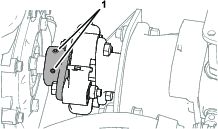
Rotate the 2 quarter-turn fastener counterclockwise to release the transmission cover (Figure 1).

-
Lift the cover and remove it from the machine.
Removing the Transmission Cover (model 44913)
-
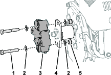
Remove the 3 capscrews (8 x 20 mm) and 3 washers (8 mm) that secure the hydraulic-reservoir mount to the transmission cover (Figure 2).
Note: Support the hydraulic tank upright.

-
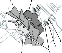
Remove the 4 capscrews (8 x 25 mm), 4 lock washers (8 mm), and 4 washers (8 mm) that secure the transmission cover to the chassis of the machine (Figure 3).

-
Lift the cover and remove it from the machine.
Removing the Engine (model 44912)
-
Remove the 2 locknuts (8 mm) and 2 washers (8 mm) that secure the fan and transmission hub to the coupler (Figure 4).
Note: Retain the nuts and washers for installation in Assembling the Coupler to the Transmission and Fan.
-
Remove the locknuts, capscrews, and washers that secure the engine to the frame of the machine (Figure 5).
Note: Access the capscrews from the underside of the machine.
Note: Retain the locknuts, capscrews, and washers for installing the engine in Assembling the Engine to the Chassis.

-
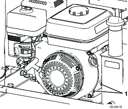
Move the engine away from the transmission, and remove the engine from the machine (Figure 6).

-
Clean the engine deck of oil and debris.
Removing the Engine (model 44913)
-
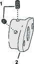
Remove the 2 locknuts (8 mm) and 2 washers (8 mm) that secure the hydraulic-pump hub to the coupler (Figure 7).
Note: Retain the nuts and washers for installation in Assembling the Coupler to the Hydraulic-Pump Hub.

-
Remove the locknuts, capscrews, and washers that secure the engine to the frame of the machine (Figure 8).
Note: Access the capscrews from the underside of the machine.
Note: Retain the locknuts, capscrews, and washers for installing the engine in Assembling the Engine to the Chassis.


-
Move the engine away from the hydraulic pump, and remove the engine from the machine (Figure 9).

-
Clean the engine deck of oil and debris.
Transferring the Oil Drain Valve
Parts needed for this procedure:
| Engine | 1 |
Draining the Engine Oil
-
Place the old engine on a level surface.
-
Install the drain hose onto the drain valve (Figure 10).
-
Place the other end of the hose (Figure 10) into a drain pan with a 1 L (1 US qt).

-
Turn the oil drain valve 1/4 turn counterclockwise and allow the engine oil to drain completely (Figure 10).
-
Turn the oil drain valve 1/4 turn clockwise to close the valve (Figure 10).
-
Remove the drain hose (Figure 10) and wipe any spilled oil.
-
Dispose of the waste oil properly.
Note: Recycle it according to local codes.
Moving the Oil Drain Valve to the New Engine

Adding Oil to the Engine
Crankcase Capacity: 0.60 L (0.63 US qt)
-
Clean the area around the oil-filler cap (Figure 12).

-
Remove the oil-filler cap by rotating it counterclockwise.
-
Fill the crankcase with the specified oil; refer to Engine Oil specification in the Operator’s Manual for your machine.
The engine is full of oil when the oil level is at the bottom edge of the oil-fill port.
Important: Do not overfill the crankcase with engine oil.

-
Install the oil-filler cap and wipe up any spilled oil.
Installing the Hub and Coupler
Parts needed for this procedure:
| Key | 1 |
| Hub | 1 |
| Set screw | 2 |
Removing the Coupler
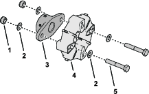
Remove the 2 locknuts (8 mm), 2 bolts (8 x 50 mm), and 4 washers (8 mm) that secure the coupler to the hub of the old engine, and remove the coupler (Figure 14).
Note: You no longer need the old engine.
Assembling the Hub and Coupler
-
Thread the 2 set screws into the new hub (Figure 15).
-
Assemble the coupler that you removed in Removing the Coupler to the new hub with the 2 bolts (8 x 50 mm), 2 washers, and 2 locknuts as shown in Figure 15.
-
Torque the nuts and bolts to 23 to 29 N∙m (17 to 21 ft-lb).
Removing the Engine Hub and Coupler
Assembling the Hub and Coupler to the Engine
-
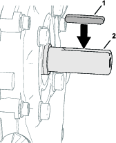
Insert the key into the slot in the crankshaft of the new engine (Figure 18).
-
Align the slot in the engine hub that you removed in Removing the Engine Hub and Coupler with the crankshaft and key of the new engine (Figure 19 or Figure 20).


-
Assemble the hub and coupler onto the crankshaft (Figure 20).
Do not tighten the set screws.
Installing the Engine to the Machine
Assembling the Coupler to the Transmission and Fan
-
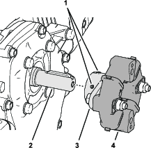
Align the holes in the coupler with the 2 bolts that align the transmission hub and fan (Figure 21).

-
Assemble the coupler onto the bolts and secure the coupler (Figure 22) with 2 washers (8 mm) and 2 locknuts (8 mm) that you removed in Removing the Engine (model 44912).
-
Torque the nuts and bolts to 23 N∙m (17 to 21 ft-lb).
Assembling the Coupler to the Hydraulic-Pump Hub
-
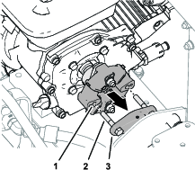
Align the holes in the coupler with the 2 bolts (8 mm) in the hydraulic-pump hub (Figure 23).
-
Assemble the coupler onto the bolts and secure the coupler (Figure 24) with 2 washers (8 mm) and 2 locknuts (8 mm) that you removed in Removing the Engine (model 44913).
-
Torque the nuts and bolts to 23 N∙m (17 to 21 ft-lb).
Assembling the Engine to the Chassis
-
Align the holes in the engine with the holes in the chassis (Figure 25 or Figure 26).
-
Assemble the engine to the chassis (Figure 25 or Figure 26) with the 2 capscrews, 8 washers and 4 locknuts that you removed in Removing the Engine (model 44912) or Removing the Engine (model 44913).
-
Torque the nuts and bolts to 23 to 29 N∙m (17 to 21 ft-lb).

Installing the Transmission Cover
Assembling the Transmission Cover to the Machine
-
Lower the transmission cover onto the machine aligning the grommets at the bottom of the cover with the studs in the chassis (Figure 29).

-
Align the quarter-turn fasteners with the receptacle clips on the flange of the panel (Figure 29).
-
Rotate the 2 quarter-turn fastener clockwise to secure the transmission cover (Figure 29).
Assembling the Transmission Cover to the Machine
-
Align the holes in the mounting flange of the transmission cover with the holes in the chassis of the machine (Figure 30).
-
Assemble the transmission cover to the chassis (Figure 30) with the 4 capscrews (8 x 25 mm), 4 lock washers (8 mm), and 4 washers (8 mm) that you removed in Removing the Transmission Cover (model 44913).
-
Torque the capscrews to 23 to 29 N∙m (17 to 21 ft-lb).
-
Align the holes in the hydraulic-reservoir mount to the threaded holes in the transmission cover (Figure 31).
-
Assemble the hydraulic-reservoir to the cover (Figure 31) with the 3 capscrews (8 x 20 mm) and 3 washers (8 mm) that you removed in Removing the Transmission Cover (model 44913).
-
Torque the capscrews to 23 to 29 N∙m (17 to 21 ft-lb).
Completing the Installation
-
Connect the spark-plug wire to the spark plug.
-
Add fuel to the fuel tank, refer to the Operator’s Manual for your machine.
-
Lower and latch the operator’s seat.