
 ), which means Caution,
Warning, or Danger—personal safety instruction. Failure to comply
with these instructions may result in personal injury or death.
), which means Caution,
Warning, or Danger—personal safety instruction. Failure to comply
with these instructions may result in personal injury or death.

Maintenance
Caution
Failure to properly maintain the machine could result in premature failure of machine systems causing possible harm to you or bystanders.
Keep the machine well maintained and in good working order as indicated in these instructions.
Note: Determine the left and right sides of the machine from the normal operating position.
Recommended Maintenance Schedule(s)
| Maintenance Service Interval | Maintenance Procedure |
|---|---|
| After each use |
|
| Every 40 hours |
|
Maintenance Safety
-
Before cleaning, servicing, or adjusting the machine, do the following:
-
Park the traction unit and machine on a level surface.
-
Shut off the traction unit engine, remove the key, and wait for all moving parts to stop.
-
Chock the wheels.
-
Remove the machine from the traction unit.
-
-
Perform only those maintenance instructions described in this manual. If major repairs are ever needed or you need assistance, contact an authorized Toro distributor.
-
Support the machine with blocks or jack stands when working beneath it.
-
Ensure that all guards are installed securely after maintaining or adjusting the machine.
-
Do not allow untrained personnel to service the machine.
-
Keep all parts in good working condition and all fasteners tightened. Replace all damaged or missing decals.
-
Do not interfere with the intended function of a safety device or reduce the protection provided by a safety device. Check their proper operation regularly.
-
Altering this machine in any manner may affect the operation of the machine, performance, durability, or its use may result in injury or death. Such use could void the product warranty of The Toro® Company.
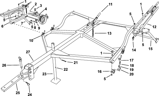
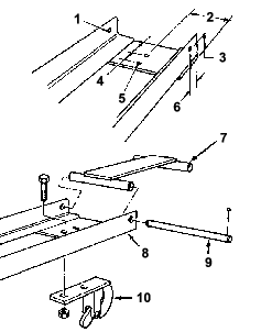
Lubricating the Machine
| Maintenance Service Interval | Maintenance Procedure |
|---|---|
| After each use |
|
-
Wipe clean each ball socket and drawbar pivot fitting with a clean, dry rag.
-
Apply No. 2 lithium grease until clean grease appears around the ball socket openings or around the pivot shafts of the drawbars.
-
Wipe away any excess grease.
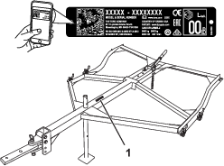
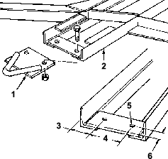
Inspecting the Frame
| Maintenance Service Interval | Maintenance Procedure |
|---|---|
| Every 40 hours |
|
-
Check the frame for any loose or missing parts.
-
Tighten any loose parts and repair or replace any broken or missing parts as necessary.