Safety
Safety and Instructional Decals
 |
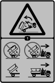
Safety decals and instructions are easily visible to the operator and are located near any area of potential danger. Replace any decal that is damaged or missing. |
Installation
Preparing the Machine
-
Park the machine on a level surface.
-
Engage the parking brake.
-
Shut off the engine and remove the key.

Removing the Cargo Bed
Remove the bed from the Toro Workman utility vehicle; refer to the Workman Operator's Manual.
Note: Retain the cylinder pins for installing this kit.
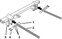
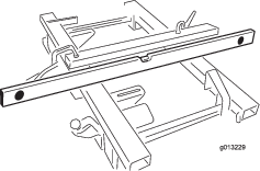
Assembling the Rear and Center Cross Members
Parts needed for this procedure:
| Rear cross member | 1 |
| Brace tube | 2 |
| Flange-head capscrew (3/8 x 2-1/2 inches) | 4 |
| Mount spacer | 2 |
| Flange locknut (3/8 inch) | 8 |
| Center cross member | |
| Flange-head capscrew (3/8 x 2 inches) | 4 |
-
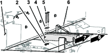
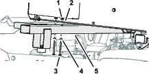
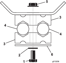
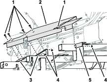
Loosely assemble a tube brace to the hinge bracket of the rear cross member with 2 spacers, 2 flange-head capscrews (3/8 x 2-1/2 inches), and 2 flange locknuts (3/8 inch) as shown in Figure 2.
-
Loosely assemble a tube brace to the hinge bracket at the other end of the rear cross member (Figure 2) with 2 spacers, 2 flange-head capscrews (3/8 x 2-1/2 inches), and 2 flange locknuts (3/8 inch).
-
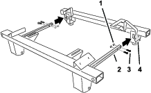
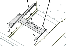
Loosely assemble the other end of the 2 brace tubes to the inner cylinder plates of the center cross member (Figure 3) with 4 flange-head capscrews (3/8 x 2 inches), and 4 flange locknuts (3/8 inch).
Assembling the Cross Members to the Machine
Parts needed for this procedure:
| Lynch pin | 2 |
| Washer (1-5/8 x 3/4 inches) | 6 |
| Hitch pin | 2 |
Assembling the Center and Rear Cross Members
-
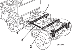
Lift the center and rear cross member assemble onto the frame rails of the machine.
-
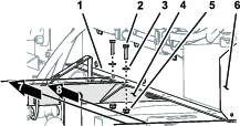
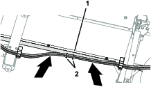
Align the holes in the pivot brackets of the rear cross member with the bed-pivot tubes in the frame rail of the machine and partially insert the 2 lynch pins through the brackets and tubes (Figure 4).
-
Insert washers (1-5/8 x 3/4 inches) as needed, between the pivot brackets and the bed-pivot tubes to center the rear cross member to the frame rails and fill the gaps (Figure 4).
-
Move the lynch pins outward and secure them with the 2 hitch pin (Figure 4).
Important: Ensure that there is clearance between the center cross member and the rear fenders of the machine and the oil filter assembly.
-
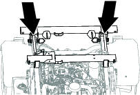
Assemble the rods of the left and right lift cylinders to the cylinder plates of the center cross member (Figure 5) with the clevis pins and lynch pins that you retained when removing the cargo bed.
Note: When installing the clevis pins, ensure that the 4 lynch pins are fully inserted and latched.
Note: You may need to move the hydraulic lift cylinder forward or backward until the clevis pins line up with the cylinder plate holes.
-
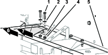
Ensure that the center cross member is square to the rear cross member.
-
Ensure that the tops of the center cross member and the rear cross member are aligned across both surfaces (Figure 6).
-
Torque the 8 flange-head capscrews and 8 flange locknuts that secure the brace tubes to the center and rear cross members to 37 to 45 N∙m (27 to 33 ft-lb).
-
Check that the center cross member and the rear cross member are square and aligned.
Installing the Top Dresser to the Utility Vehicle
Parts needed for this procedure:
| Capscrew (5/16 x 3 inches) | 6 |
| Flange locknut (5/16 inch) | 12 |
| Washer (5/16 inch) | 12 |
| Capscrew (5/16 x 1-1/4 inches) | 6 |
Assembling the Top Dresser to the Center Cross Members
Warning
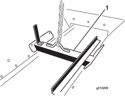
Do not lift the top dresser bed and hopper while they are assembled to the Workman chassis. The lifting bracket cannot lift the entire machine.
Lifting equipment capacity: 413 kg (910 lb)
-
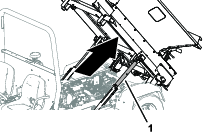
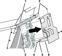
Attach a lifting equipment to the lifting bracket bolted inside the hopper of the top dresser (Figure 8).
-
Lift the top dresser high enough to back the vehicle underneath.
-
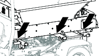
Carefully lower the top dresser onto the vehicle and align the holes in the left rail of the top dresser that measure 107.6 cm (42-3/8 inches) and 112.7 cm (44-3/8 inches) from the rinse guard with the holes in the center cross member (Figure 10 and Figure 11).
-
Loosely assemble the rail to the left side of the center cross member (Figure 11) with 2 capscrews (5/16 x 3 inches), 2 washers (5/16 inch), and flange locknut (5/16 inch).
-
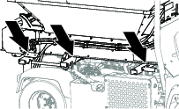
At the right top-dresser rail, measure 103.7 cm (40-13/16 inches) and 116.7 cm (45-15/16 inches) from the rinse guard to the holes in the rail (Figure 12).
-
Loosely assemble the rail to the center cross member mount plate (Figure 12) with capscrews (5/16 x 1-1/4 inches), 2 washers (5/16 inch), and flange locknut (5/16 inch).
Assembling the Top Dresser to the Rear Cross Member
-
Measure 146.5 cm (57-11/16 inches) and 151.6 cm (59-11/16 inches) from the rinse guard to the holes in the rail (Figure 13).
-
Assemble rail to the slotted bracket of the rear cross member (Figure 10 and Figure 13) with 2 capscrews (5/16 x 1-1/4 inches), 2 washers (5/16 inch), and flange locknut (5/16 inch).
-
Repeat steps 1 and 2 for the rear cross member at the other side of the machine.
-
Torque the 8 capscrews and 8 flange locknuts at the center and rear cross members to 1978 to 2542 N∙m (175 to 225 in-lb).
Assembling the Top Dresser to the Front Cross Member
-
Use the cargo bed-lift cylinders of the vehicle to raise the top dresser 51 mm (2 inches).
-
Lift the front cross member to the rail of the top dresser and assemble the cross member to the rail (Figure 15) with 2 capscrews (5/16 x 3 inches), 2 washers, and (5/16 inch), and 2 flange locknuts (5/16 inch).
-
Repeat step 2 for the front cross member at the other side of the machine.
-
Torque the capscrews and locknuts for the front cross member to 1978 to 2542 N∙m (175 to 225 in-lb).
Installing the Hydraulic Hoses
Parts needed for this procedure:
| Pressure hydraulic hose | 1 |
| Return hydraulic hose | 1 |
| Capscrew (1/4 x 2-3/4 inches) | 3 |
| Washer (1/4 inch) | 3 |
| Clamp plate | 3 |
| Tube clamp half | 6 |
| Flange locknut (1/4 inch) | 3 |
| Cable tie | 2 |
Raising the Top Dresser
Removing the Top Dresser Hydraulic Guard
Connecting the Hoses to the Control Valve Fittings
-
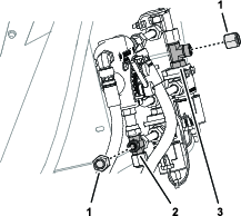
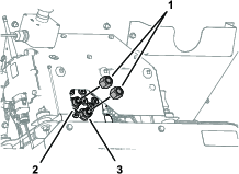
At the valve mount, remove the caps from the T-fitting and the cross union fitting as shown in Figure 18.
-
Loosely assemble the 90° fitting of the return hydraulic hose (the hose with the arrow decal affixed) onto the T-fitting (Figure 19).
-
Loosely assemble the 45° fitting of the pressure hydraulic hose onto the cross union fitting (Figure 19).
-
Route the hoses toward the forward right corner of the top dresser.
Connecting the Hoses to the Hydraulic Manifold
-
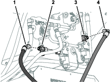
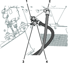
Remove the caps from the from the union fittings at port-T and port-P of the hydraulic manifold (Figure 20).
-
Loosely assemble the 45° fitting of the pressure hydraulic hose onto the union fitting in port-P (Figure 21).
-
Loosely assemble the 90° fitting of the return hydraulic hose (the hose with the arrow decal affixed) onto port-T of the hydraulic manifold (Figure 21).
Routing the Hydraulic Hoses
-
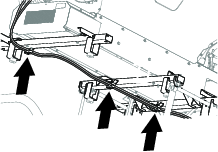
Route the hydraulic pressure and return hoses along the right the top dresser frame rail as shown in Figure 22.
-
Loosely assemble the hoses to the 3 hose-mount brackets located at the front, center and rear cross members (Figure 22 and Figure 23) with a 3 capscrews (1/4 x 2-3/4 inches), 3 washers (1/4 inch), 3 clamp plates, 6 tube-clamp halves, and 3 flange locknuts (1/4 inch).
-
Between the front and center cross members, route the hoses against the right frame rail (Figure 24).
-
Secure the hoses to the holes in the frame rail with 2 cable ties (Figure 24). When attaching the hose, ensure that there is proper tension on the hoses.
Note: Remove any slack in the hoses so that they bend upward to clear the engine of the Workman.
-
Tighten the 3 capscrews and 3 locknuts that secure the tube-clamp halves (Figure 23).
-
Tighten the 90° fitting of the return hydraulic hose and the 45° fitting of the pressure hydraulic hose; refer to Figure 19 or Figure 21.
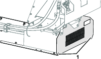
Installing the Top Dresser Hydraulic Guard
-
Align the holes in the hydraulic guard with the holes in the valve mount and the front wall of the hopper (Figure 25).
-
Secure the hydraulic guard to the hopper wall (Figure 25) with the 2 button-head screws that you removed in Removing the Top Dresser Hydraulic Guard.
-
Secure the hydraulic guard to the valve mount with the 2 capscrews and 2 washers that you removed in Removing the Top Dresser Hydraulic Guard.
Installing Top Dresser Wire Harness and Optional Equipment
Important: When routing either the hydraulic hoses or the electrical wire harness, always make sure that you route them away from of all hot, sharp, or moving components and always ensure that there is no stress on the hoses or wire harness. This may require loosening and repositioning the hydraulic hose at the front bulkhead.
-
Route and connect the top dresser electrical harness; refer to the Operators Manual for the top dresser.
Note: If the electrical connection is installed near the battery of the Workman vehicle, route the electrical power cord from the top dresser to the back of the vehicle, at the pivot location, then forward to the battery.
Note: If the electrical connection is installed at the rear of the vehicle, route and secure the electrical power cord to the hydraulic pressure and return hoses from the front to the rear of the top dresser.
-
Install the optional equipment and connect the hydraulic hoses to the top dresser; refer to the Installation Instructions for the optional equipment.
Note: Ensure that the pressure and return hoses are attached to the rear of the Workman and do not contact with the optional equipment.
Installing the Side Shields
Parts needed for this procedure:
| Left side shield | 1 |
| Right side shield | 1 |
| Flange-head capscrew (1/4 x 3/4 inch) | 10 |
| Flange locknut (1/4 inch) | 6 |
-
Align the slots in the side shield with the slots in the 2 shield supports of the center and rear cross members and the L-bracket of the front cross member (Figure 27).
-
Assemble the side shield to the shield support at the center cross member (Figure 27) with 2 flange-head capscrews(1/4 x 3/4 inch) and 2 flange locknuts (1/4 inch).
-
Assemble the side shield to the L-bracket at the front cross member (Figure 27) with a flange-head capscrew (1/4 x 3/4 inch) and a flange locknut (1/4 inch).
-
Assemble the side shield to the shield support at the rear cross member (Figure 27) with 2 flange-head capscrews(1/4 x 3/4 inch).
-
Torque the capscrews and locknuts to 1017 to 1243 N∙m (90 to 110 in-lb).
-
Repeat steps 1 through 5 for the side shield at the other side of the machine.
Connecting the Hydraulic Hoses to the Vehicle
-
Remove bed support from the lift cylinder of the vehicle and stow the support.
-
Lower the top dresser onto the chassis of the vehicle.
-
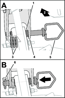
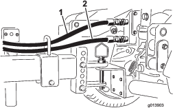
Plug the quick-disconnect fitting of the return hose (the hose with the arrow decal affixed) into the upper quick-disconnect fitting of the vehicle (Figure 28).
-
Plug the quick-disconnect fitting of the pressure hose into the lower quick-disconnect fitting of the vehicle (Figure 28).
Completing the Chassis Mount Kit Installation
-
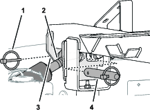
Remove the 4 button-head screws that secure the lifting bracket to the wall of the hopper (Figure 29).
-
Assemble the button-head screws into the wall of the hopper and tighten the screws (Figure 29).
-
For Model 44701, connect the On/Off pendant to the top dresser and place the pendant in the seating area of the vehicle.