Windshield Kit
Workman® HD Series Utility Vehicle with Canopy
Workman® HD Series Utility Vehicle with Canopy
Park the machine on a level surface.
Engage the parking brake.
Shut off the engine and remove the key.

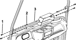
While grasping the hood in the headlight openings, lift up the hood to release the lower mounting tabs from the frame slots (Figure 2).
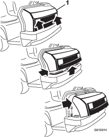
Pivot the bottom of the hood upward until you can pull the top mounting tabs from the frame slots (Figure 2).
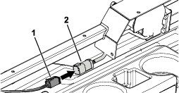
Pivot the top of the hood forward and unplug the wire connectors from the headlights (Figure 2).
Remove the hood.
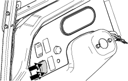
Drill a hole (9.5 mm or 3/8 inch) in the dash centered at the passenger side cup holder using the dimensions shown in Figure 3.
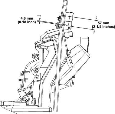
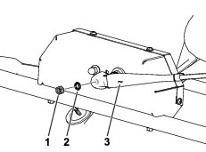
Measure down 4.6 mm (0.18 inch) from the existing hole (9.9 mm or 0.391 inch) in the canopy support tube (Figure 4).
Drill the first hole (7.1 mm or 0.281 inch) in the canopy support tube (Figure 4).
Ensure that you drill through both walls of the canopy support tube.
Measure 57 mm (2-1/4 inches) up from the hole you drilled, and drill the second hole (7.1 mm or 0.281 inch) in the canopy support tube (Figure 4).
Ensure that you drill through both walls of the canopy support tube.
Repeat this procedure on the other side of the machine.
Parts needed for this procedure:
| Windshield support assembly | 1 |
| Flange-head bolt (1/4 x 1-1/2 inches) | 4 |
| Locknut (1/4 inch) | 4 |
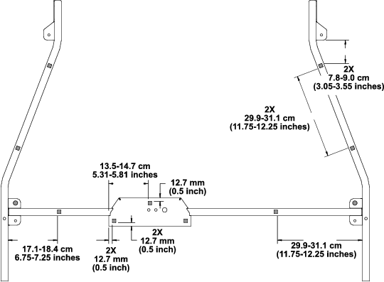
Secure the windshield support assembly to the canopy support tubes using 4 flange-head bolts (1/4 x 1-1/2 inches) and 4 locknuts (1/4 inch) as shown in Figure 5.
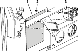
Parts needed for this procedure:
| Wiper motor assembly | 1 |
Disassemble the fasteners from the wiper motor assembly as shown in Figure 7.

Secure the wiper motor assembly to the motor mount bracket using the previously removed hardware as shown in Figure 8.

Torque the acorn nut to 23 to 28 N∙m (17 to 21 ft-lb) and torque the wiper stud nut to 23 to 28 N∙m (17 to 21 ft-lb).
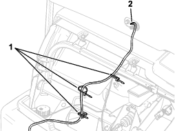
Parts needed for this procedure:
| Wire harness | 1 |
| Rocker switch | 1 |
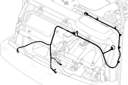
Route the wire harness as shown in Figure 9.
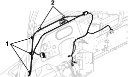
Secure the wire harness to the left canopy support tube and windshield support assembly using the magnetic tie wraps and push-mount fasteners on the wire harness (Figure 10).
Connect the wire harness to the connector on the wiper motor (Figure 11).
Remove the plug from the dash and install the rocker switch in the opening.
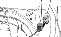
Connect the 8-socket connector on the wire harness to the rocker switch in the dash (Figure 12).
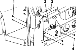
Parts needed for this procedure:
| Wiper motor cover | 1 |
| Speed nut | 4 |
| Phillips-head screw (#10 x 1/2 inch) | 4 |
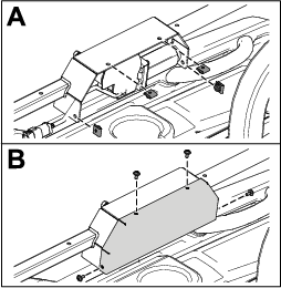
Secure the wiper motor cover to the motor mount bracket using the 4 speed nuts and 4 Phillips-head screws (#10 x 1/2 inch) as shown in Figure 13.
Parts needed for this procedure:
| Windshield trim | 1 |
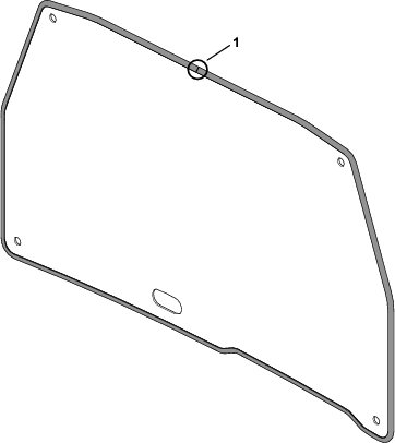
Starting with the seam of the trim at the top, center of the windshield, use a rubber mallet to install the trim around the windshield (Figure 14).
Note: After installing the trim, you may need to trim the length of the edge of the trim.
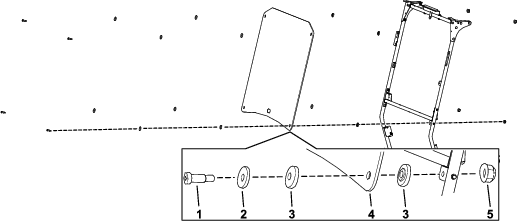
Parts needed for this procedure:
| Windshield | 1 |
| Shoulder bolt (5/16 x 1-1/4 inches) | 4 |
| Flange bushing | 8 |
| Flange nut (5/16 inch) | 4 |
| Backup washer | 4 |
Install the windshield to the windshield supports using 4 shoulder bolts (5/16 x 1-1/4 inches), 4 backup washers, 8 flange bushings, 4 flange nuts (5/16 inch) as shown in Figure 15.
Run the wiper motor through a complete cycle to ensure that the wiper shaft positions correctly.
Parts needed for this procedure:
| Washer tank | 1 |
| Tank mounting bracket | 1 |
| U-bolt | 2 |
| Carriage bolt (5/16 x 3/4 inch) | 4 |
| Flange nut (5/16 inch) | 8 |
| Wiper hose | 1 |
| Barbed hose fitting | 1 |
| Cable tie | 3 |
Secure the tank mounting bracket to the machine support tube using the 2 U-bolts and 4 flange nuts (5/16 inch) as shown in Figure 16.
Secure the washer tank to the tank mounting bracket using 4 carriage bolts (5/16 x 3/4 inch) and 4 flange nuts (5/16 inch) as shown in Figure 17.
Connect the wiper hose to the washer tank (Figure 18).
Route the wiper hose from the washer tank to the wiper motor and secure it using the 3 cable ties (Figure 18).
Install the barbed hose fitting in the opening of the wiper motor and connect the other end of the wiper hose (Figure 18).
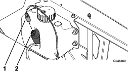
Insert the wire-harness connector onto the tank connector until the connector fully seats (Figure 19).
Parts needed for this procedure:
| Wiper arm | 1 |
| Wiper blade | 1 |
Run the wiper motor for at least 1 cycle and allow it to return to its normal position.
Secure the wiper blade to the wiper arm.
Use the lock washer and wiper stud nut to install the arm to the motor (Figure 20).
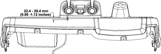
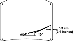
Position the arm using the measurements shown in Figure 21.
Torque the wiper stud nut to 23 to 29 N∙m (17 to 21 ft-lb).
Press the rocker switch to turn the wipers to the ON or OFF position (Figure 22).