| Maintenance Service Interval | Maintenance Procedure |
|---|---|
| After the first 10 hours |
|
Introduction
The debris blower is towed behind a ride-on machine which is intended to be used by professional, hired operators in commercial applications. It is primarily designed to use wind power to quickly clear large areas of unwanted debris on well-maintained lawns in parks, golf courses, sports fields, and on commercial grounds. Using this product for purposes other than its intended use could prove dangerous to you and bystanders.
Read this information carefully to learn how to operate and maintain your product properly and to avoid injury and product damage. You are responsible for operating the product properly and safely.
Visit www.Toro.com for product safety and operation training materials, accessory information, help finding a dealer, or to register your product.
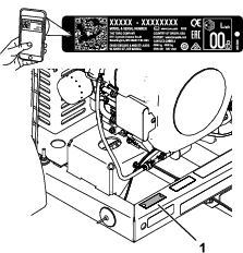
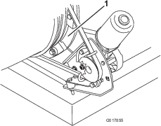
Whenever you need service, genuine Toro parts, or additional information, contact an Authorized Service Dealer or Toro Customer Service and have the model and serial numbers of your product ready. Figure 1 identifies the location of the model and serial numbers on the product. Write the numbers in the space provided.
Important: With your mobile device, you can scan the QR code on the serial number (if equipped) to access warranty, parts, and other product information.
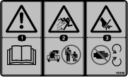
This manual identifies potential hazards and has safety messages identified by the safety-alert symbol (Figure 2), which signals a hazard that may cause serious injury or death if you do not follow the recommended precautions.

This manual uses 2 words to highlight information. Important calls attention to special mechanical information and Note emphasizes general information worthy of special attention.
This product complies with all relevant European directives; for details, please see the separate product specific Declaration of Conformity (DOC) sheet.
It is a violation of California Public Resource Code Section 4442 or 4443 to use or operate the engine on any forest-covered, brush-covered, or grass-covered land unless the engine is equipped with a spark arrester, as defined in Section 4442, maintained in effective working order or the engine is constructed, equipped, and maintained for the prevention of fire.
The enclosed engine owner's manual is supplied for information regarding the US Environmental Protection Agency (EPA) and the California Emission Control Regulation of emission systems, maintenance, and warranty. Replacements may be ordered through the engine manufacturer.
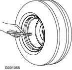
The DOT tire information is located on the side of each tire. This information gives load and speed ratings. Replacement tires should have the same or better ratings. Ensure that the tires meet or exceed the weight requirements of your machine.
| Electromagnetic Compatibility |
| Domestic: This device complies with FCC Rules Part 15. Operation is subject to the following two conditions: (1) This device may not cause harmful interference and (2) this device must accept any interference that may be received, including interference that may cause undesirable operation. |
| This equipment generates and uses radio frequency energy and if not installed and used properly, in strict accordance with the manufacturer's instructions, may cause interference to radio and television reception. It has been type tested and found to comply within the limits of a FCC Class B computing device in accordance with the specifications in Subpart J of Part 15 of FCC Rules, as stated above. However, there is no guarantee that interference will not occur in a particular installation. If this equipment does cause interference to radio or television reception, which can be determined by turning the equipment off and on, the user is encouraged to try to correct the interference by one or more of the following measures:Reorient the receiving antenna, relocate the remote control receiver with respect to the radio/TV antenna or plug the controller into a different outlet so that the controller and radio/TV are on different branch circuits.If necessary, the user should consult the dealer or an experienced radio/television technician for additional suggestions.The user may find the following booklet prepared by the Federal Communications Commission helpful: "How to Identify and Resolve Radio-TV Interference Problems". This booklet is available from the U.S. Government Printing Office, Washington, DC 20402. Stock No. 004-000-00345-4. |
| FCC ID: W7OMRF24J40MDME-Base, OA3MRF24J40MA-Hand Held |
| IC: 7693A-24J40MDME-Base, 7693A-24J40MA-Hand Held |
| Operation is subject to the following two conditions: (1) this device may not cause interference, and (2) this device must accept any interference, including interference that may cause undesired operation of the device. |
| Japan Electromagnetic Compatibility Certification | |
| Handheld: |  |
| RF2CAN: |  |
| Mexico Electromagnetic Compatibility Certification | |
| Handheld: |  |
| RF2CAN: |  |
| Korea Electromagnetic Compatibility Certification(Decal provided in separate kit) | |
| Handheld: |  |
| RF2CAN: |  |
| Singapore Electromagnetic Compatibility Certification | |
| Handheld: | TWM240007_IDA_N4021–15 |
| RF2CAN: | TWM-240005_IDA_N4024–15 |
| Morocco Electromagnetic Compatibility Certification | |
| AGREE PAR L’ANRT MAROC | |
| Numero d’agrement: | MR 14092 ANRT 2017 |
| Delivre d’agrement: | 29/05/2017 |
Caution
Changing or modifying the machine without the express approval from the party responsible for compliance could void your authority to operate the equipment.
Do not change or modify the machine without the express approval from the party responsible for compliance.
Warning
CALIFORNIA
Proposition 65 Warning
The engine exhaust from this product contains chemicals known to the State of California to cause cancer, birth defects, or other reproductive harm.
Battery posts, terminals, and related accessories contain lead and lead compounds, chemicals known to the State of California to cause cancer and reproductive harm. Wash hands after handling.
Use of this product may cause exposure to chemicals known to the State of California to cause cancer, birth defects, or other reproductive harm.
Safety
This machine has been designed in accordance with ANSI standard B71.4-2017.
General Safety
This product is capable of throwing objects. Always follow all safety instructions to avoid serious personal injury.
-
Read and understand the contents of both this Operator’s Manual and the operator’s manual of the traction unit before using this machine. Ensure that everyone using this product knows how to use this machine and the traction unit and understands the warnings.
-
Use your full attention while operating the machine. Do not engage in any activity that causes distractions; otherwise, injury or property damage may occur.
-
Do not put your hands or feet near moving components of the machine.
-
Do not operate the machine without all guards and other safety protective devices in place and working on the machine.
-
Keep children, bystanders, and pets out of the operating area. Never allow children to operate the machine.
-
Always shut off the engine, remove the key (if equipped), wait for all moving parts to stop, and allow the machine to cool before adjusting, repairing, cleaning, or storing the machine.
Improperly using or maintaining this machine can result in injury. To reduce the potential for injury, comply with these safety instructions and always pay attention to the safety-alert symbol (Figure 2), which means Caution, Warning, or Danger—personal safety instruction. Failure to comply with these instructions may result in personal injury or death.
Safety and Instructional Decals
 |
Safety decals and instructions are easily visible to the operator and are located near any area of potential danger. Replace any decal that is damaged or missing. |


Setup
Note: Determine the left and right sides of the machine from the normal operating position.
Connecting the Battery
Parts needed for this procedure:
| Grafo 112X grease (Toro Part No. 505-47) | — |
-
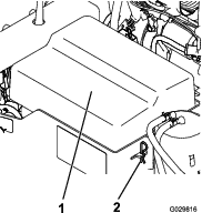
Remove the clips securing the battery cover to the battery box (Figure 3).
Danger
Battery electrolyte contains sulfuric acid, which is fatal if consumed and causes severe burns.
-
Do not drink electrolyte and avoid contact with skin, eyes or clothing. Wear safety glasses to shield your eyes and rubber gloves to protect your hands.
-
Fill the battery where clean water is always available for flushing the skin.
-
-
Attach the positive cable (red cable) to the positive (+) terminal.
-
Attach the negative cable (black cable) to the negative (-) terminal of the battery.
-
Coat the terminals and mounting fasteners with Grafo 112X (skin over) grease (Toro Part No. 505-47) to prevent corrosion.
-
Install the battery cover and secure with the clips.
Mounting the Hitch to the Debris Blower
Parts needed for this procedure:
| Debris blower assembly | 1 |
| Hitch | 1 |
| Bolt (3/8 x 3 inches) | 2 |
| Flange nut (3/8 inch) | 2 |
| Hitch clevis | 1 |
| Bolt (5/8 x 4–1/2 inch) | 2 |
| Locknut (5/8 inch) | 2 |
-
Position the debris blower on a flat, level surface.
-
Insert the hitch tube into the frame brackets (Figure 4). Secure the tube to the frame with 2 bolts (3/8 x 3 inches) and flange nuts (3/8 inch) and torque to 40 N⋅m (30 ft-lb).
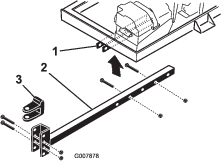
Note: The hitch tube can be rotated 180 degrees to accommodate different hitch heights.
Connecting the Debris Blower to the Tow Vehicle
Parts needed for this procedure:
| Hitch pin | 1 |
| Clevis | 1 |
-
Back the tow vehicle up to the blower.
-
Adjust the blower hitch clevis to the same level as the tow vehicle hitch as follows:
-
Set the hitch tube on a jack stand to keep it parallel to the ground.
-
Remove the bolts and locknuts securing the hitch clevis (Figure 4) to the hitch tube.
-
Raise or lower the hitch clevis to the position approximately level with the tow vehicle hitch.
-
Secure the clevis to the hitch with the bolts and locknuts previously removed and torque to 203 N⋅m (150 ft-lb). Make sure debris blower frame is parallel with the ground.
-
-
Adjust the hitch tube length to assure the blower does not contact the tow vehicle when turning as follows:
-
Remove the bolts and nuts securing the hitch tube to the frame brackets (Figure 4).
-
Secure the tube to the frame with the bolts and flange nuts.
-
-
Connect the blower clevis hitch to the tow vehicle hitch with the hitch pin and clevis (Figure 5).

Assembling the Handheld Remote
Parts needed for this procedure:
| Handheld remote | 1 |
| AAA batteries | 4 |
| Screws (small) | 6 |
-
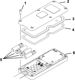
Remove the rubber bands securing the remote halves together, and remove the back cover.
-
Plug each battery into a terminal cradle observing proper polarity (Figure 6).
Note: If the batteries are improperly installed, the machine will not be damaged, but it will fail to operate. The cradle is embossed with polarity markings for each terminal.
-
Ensure that the steel gasket and rubber seal are seated in the channel in the remote and set the back cover in place (Figure 6).
-
Secure the cover with 6 screws (Figure 6) and torque them to 1.5 to 1.7 N⋅m (13 to 15 in-lb).
Product Overview
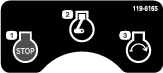
Engine Stop
Press the Engine Stop button to shut off the engine (Figure 7).
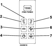
Engine Start
After completing the starting sequence, press the Engine Start button to start the engine (Figure 7). Refer to Starting the Engine for the starting sequence.
Blower Nozzle Direction
Press the right or left button to rotate the blower nozzle to the desired direction (Figure 7).
Engine Speed
Press the Increase Engine Speed (rabbit) or Decrease Engine Speed (turtle) button to increase or decrease the speed of the engine (Figure 7). Pressing the Increase Engine Speed and Decrease Engine Speed buttons at the same time returns the engine to idle.
Ignition Switch
The ignition switch (Figure 8), which is used to start and stop the engine, has three positions: OFF, RUN and START. Rotate the key clockwise to START to engage the starter motor. Release the key when the engine starts. The key moves automatically to the RUN position. To shut the engine off, rotate the key counterclockwise to the OFF position.
Choke Control
To start a cold engine, move the choke control lever (Figure 8) to the ON position.
Hour Meter
The hour meter (Figure 8) indicates the total hours of machine operation.
Diagnostic Light
The diagnostic light (Figure 9) is located below the hour meter and indicates machine fault codes. After you turn the key to the RUN position, the diagnostic light illuminates for 5 seconds, turns off for 5 seconds, and then flashes 3 times a second until you push a button on the handheld remote. If the light turns on for 5 seconds and then starts blinking 10 times a second (with or without a 5-second pause) there is a fault with the machine; refer to Checking Fault Codes.
Note: If you press a button on the handheld remote when you start the machine, the light does not flash 3 times a second after it turns off for 5 seconds.
Radio Specifications
| Frequency | 2.4 GHz |
| Max output power | 19.59 dBm |
Attachments/Accessories
A selection of Toro approved attachments and accessories is available for use with the machine to enhance and expand its capabilities. Contact your Authorized Service Dealer or authorized Toro distributor or go to www.Toro.com for a list of all approved attachments and accessories.
To ensure optimum performance and continued safety certification of the machine, use only genuine Toro replacement parts and accessories. Replacement parts and accessories made by other manufacturers could be dangerous, and such use could void the product warranty.
Operation
Note: Determine the left and right sides of the machine from the normal operating position.
Before Operation
Before Operation Safety
General Safety
-
Never allow children or untrained people to operate or service the machine. Local regulations may restrict the age of the operator. The owner is responsible for training all operators and mechanics.
-
Become familiar with the safe operation of the equipment, operator controls, and safety signs.
-
Always shut off the engine, remove the key, wait for all moving parts to stop, and allow the machine to cool before adjusting, repairing, cleaning, or storing the machine. Know how to stop the machine and shut off the engine quickly.
-
Keep all guards, safety devices, and decals in place. Repair or replace all safety devices and replace all illegible or missing decals. Do not operate the machine unless they are present and functioning properly.
-
Ensure that the traction unit is suitable for use with an implement of this weight by checking with the traction unit supplier or manufacturer.
-
Do not modify this equipment in any manner.
Fuel Safety
-
Use extreme care in handling fuel. It is flammable and its vapors are explosive.
-
Extinguish all cigarettes, cigars, pipes, and other sources of ignition.
-
Use only an approved fuel container.
-
Do not remove the fuel cap or fill the fuel tank while the engine is running or hot.
-
Do not add or drain fuel in an enclosed space.
-
Do not store the machine or fuel container where there is an open flame, spark, or pilot light, such as on a water heater or other appliance.
-
If you spill fuel, do not attempt to start the engine; avoid creating any source of ignition until the fuel vapors have dissipated.
Adding Fuel
-
Fuel tank capacity: 18.9 L (5 US gallons)
-
Recommended Fuel
-
For best results, use only clean, fresh (less than 30 days old), unleaded fuel with an octane rating of 87 or higher ((R+M)/2 rating method).
-
Ethanol: Fuel with up to 10% ethanol (gasohol) or 15% MTBE (methyl tertiary butyl ether) by volume is acceptable. Ethanol and MTBE are not the same. Fuel with 15% ethanol (E15) by volume is not approved for use. Never use fuel that contains more than 10% ethanol by volume, such as E15 (contains 15% ethanol), E20 (contains 20% ethanol), or E85 (contains up to 85% ethanol). Using unapproved fuel may cause performance problems and/or engine damage which may not be covered under warranty.
-
Do not use fuel containing methanol.
-
Do not store fuel either in the fuel tank or fuel containers over the winter unless a fuel stabilizer is used.
-
Do not add oil to fuel.
-
Important: Do not use fuel additives other than a fuel stabilizer/conditioner. Do not use fuel stabilizers with an alcohol base, such as ethanol, methanol, or isopropanol.
Using Stabilizer/Conditioner
Use a fuel stabilizer/conditioner in the machine to provide the following benefits:
-
Keeps fuel fresh during storage of 90 days or less. For longer storage it is recommended that the fuel tank be drained.
-
Cleans the engine while it runs
-
Eliminates gum-like varnish buildup in the fuel system, which causes hard starting
Important: Do not use fuel additives containing methanol or ethanol.
Add the correct amount of fuel stabilizer/conditioner to the fuel.
Note: A fuel stabilizer/conditioner is most effective when mixed with fresh fuel. To minimize the chance of varnish deposits in the fuel system, use fuel stabilizer at all times.
Filling the Fuel Tank
-
Shut the engine off.
-
Clean the area around the fuel tank cap and remove the cap (Figure 10).
Note: The fuel tank cap contains a gauge which shows the fuel level.
-
Add fuel to the fuel tank until the level is 6 mm to 13 mm (1/4 to 1/2 inch) below the bottom of the filler neck.
Note: This space in the tank allows fuel to expand. Do not fill the fuel tanks completely full.
-
Install fuel tank cap securely.
-
Wipe up any fuel that may have spilled.
Checking the Engine-Oil Level
Before you start the engine and use the machine, check the oil level in the engine crankcase; refer to Checking the Engine-Oil Level.
Checking the Tire Pressure
Checking the Torque of the Wheel Lug Nuts
Check the torque of the wheel lug nuts initially and after the first 10 hours of operation.
Warning
Failure to maintain proper torque could result in failure or loss of wheel and could result in personal injury.
Torque wheel lug nuts to 95 to 122 N⋅m (70 to 90 ft-lb).
During Operation
During Operation Safety
General Safety
-
The owner/operator can prevent and is responsible for accidents that may cause personal injury or property damage.
-
Wear appropriate clothing, including eye protection; long pants; substantial, slip-resistant footwear; and hearing protection. Tie back long hair and do not wear loose jewelry.
-
Do not operate the machine while ill, tired, or under the influence of alcohol or drugs.
-
Use your full attention while operating the machine. Do not engage in any activity that causes distractions; otherwise, injury or property damage may occur.
-
Discharged air has considerable force and could cause injury or loss of footing. Stay away from the blower nozzle when the machine is operating.
-
Keep all bystanders away; shut off the machine when bystanders enter the area, do not direct discharge toward them.
-
Do not operate the machine when it is not connected to a towing vehicle.
-
Do not run the engine in or direct the blower nozzle into a confined area without adequate ventilation. Engine exhaust contains carbon monoxide, an odorless gas that is fatal if inhaled.
-
Do not carry passengers on the machine and keep bystanders and pets away from the machine during operation.
-
Operate the machine only in good visibility to avoid holes or hidden hazards.
-
Look behind and down before backing up to be sure of a clear path.
-
Use care when approaching blind corners, shrubs, trees, or other objects that may obscure your vision.
-
Never run an engine in an area where exhaust gasses are enclosed.
-
Never leave a running machine unattended.
-
When transporting the machine on public roads, follow all traffic regulations and use any additional accessories that may be required by law, such as lights, turn signals, slow-moving vehicle (SMV) signs, and others as required.
-
If the machine ever vibrates abnormally, stop the machine immediately, shut off the engine, remove the key, wait for all moving parts to stop, and inspect for damage. Repair all damage to the machine before resuming operation.
-
Reduce speed when operating on rough, uneven terrain, and near curbs, holes, and other sudden changes in terrain.
-
To avoid causing the machine to tip over, be careful when turning and avoid unsafe maneuvers.
Slope Safety
-
Slopes are a major factor related to loss of control and rollover accidents, which can result in severe injury or death. You are responsible for safe slope operation. Operating the machine on any slope requires extra caution.
-
Review the traction unit specifications to ensure that you do not exceed its slope capabilities.
-
Evaluate the site conditions to determine if the slope is safe for machine operation, including surveying the site. Always use common sense and good judgment when performing this survey.
-
Review the slope instructions, listed below, for operating the machine on slopes. Before you operate the machine, review the site conditions to determine whether you can operate the machine in the conditions on that day and at that site. Changes in the terrain can result in a change in slope operation for the machine.
-
Avoid starting, stopping, or turning the machine on slopes. Avoid making sudden changes in speed or direction. Make turns slowly and gradually.
-
Do not operate a machine under any conditions where traction, steering, or stability is in question.
-
Remove or mark obstructions such as ditches, holes, ruts, bumps, rocks, or other hidden hazards. Tall grass can hide obstructions. Uneven terrain could overturn the machine.
-
Be aware that operating the machine on wet grass, across slopes, or downhill may cause the machine to lose traction.
-
Use extreme caution when operating the machine near drop-offs, ditches, embankments, water hazards, or other hazards. The machine could suddenly roll over if a wheel goes over the edge or the edge caves in. Establish a safety area between the machine and any hazard.
-
Remote Control Operation
-
Failure to abide by the safety precautions may result in equipment failure, loss of authority to operate the equipment, and personal injury.
-
Use and maintain the proper wiring. Follow the equipment manufacturer instructions. Improper, loose, and frayed wiring can cause system failure, equipment damage, and intermittent operation.
-
Changes or modifications made to the machine that are not expressly approved by the manufacturer will void the warranty
-
The machine owner and operators must abide by all applicable federal, state, and local laws concerning machine installation and operation. Failure to comply could result in penalties and could void the user’s authority to operate the machine.
-
Ensure that the machinery and surrounding area is clear before operating. Do not activate the remote control system until you are certain that it is safe to do so.
-
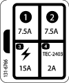
You can remove the power from the RF2CAN and TEC2403 controllers by removing the source power from the circuit.
-
Use a damp cloth to keep the remote clean. Remove mud, concrete, and dirt after operation to prevent obstructing or clogging the buttons, levers, wiring, and switches.
-
Do not allow liquid to enter the remote control or base-unit enclosures. Do not use high-pressure equipment to clean the remote control or base unit.
-
Disconnect the RF2CAN and TEC2403 controllers before welding on the machine. Failure to disconnect the controllers may result in destruction of or damage to the controllers.
-
Operate and store the machine only within the specified operation and storage temperatures.
Starting the Engine
Warning
Rotating parts can cause serious personal injury.
-
Keep your hands, feet, hair, and clothing away from all moving parts to prevent injury.
-
Never operate the machine with covers, shrouds, or guards removed.
-
Ensure that the blower is attached to the tow vehicle before you start the blower.
-
Move the choke control to the ON position before starting a cold engine.
Note: A warm or hot engine may not require choking. After the engine starts, move the choke control to the OFF position.
-
Rotate the engine ignition key to the START position (Figure 12).
Note: If the key was left in the RUN position for an extended time, move the key to the OFF position before proceeding to the starting procedure.
-
Engine Start only becomes energized by pressing the Start button while the Engine Start Enable Condition is active. The Engine Start Enable Condition becomes active only when you have performed the following Engine Start Enable Sequence (Figure 13):
-
Press the START button.
-
Then, press the rotate left button.
-
Then, press the rotate right button.
-
Then, press and hold the START button until the engine starts.
Note: There is a time limit of 3 seconds between each button press. If the next button in the sequence is not pressed within 3 seconds of the last button press, the sequence is aborted and must be started from the beginning.
Note: If you press any button other than the next appropriate button in the sequence, the sequence is aborted.
Note: If you do not press the START button within 10 seconds after pressing the ROTATE RIGHT button, or if you press any other button during this period, the Engine Start Enable Condition expires.
Note: Engine Start Enable Condition persists for 10 seconds after pressing the ROTATE RIGHT button allowing momentary activation of Engine Start by pressing the START button. Pressing the START button does not extend this time period—the maximum length of time that the Start Relay Control can be active is 10 seconds from pressing the ROTATE RIGHT button. After the Engine Start Enable Condition expires, you must perform the Engine Start Enable Sequence again in order to energize the Start Relay Control with the START button. You cannot perform this sequence for 10 seconds after you release the START button.
Note: If the sequence is aborted or the Engine Start Enable Condition expires, normal functionality of the ROTATE RIGHT and ROTATE LEFT buttons return to control the Chute Motor.
Important: Do not engage starter for more than 10 seconds at a time. If engine fails to start, allow a 10-second cool-down period between attempts. Failure to follow these instructions can burn out starter motor.
-
-
After the engine starts, move the choke control to the OFF position. If the engine stalls or hesitates, move the choke back to the ON position for a few seconds, then set the engine speed to the desired setting. Repeat this as required.
Shutting Off the Engine
-
Decrease the engine speed to 3/4 throttle.
-
Press the STOP button on the remote control.
-
If leaving the machine, rotate the key to the OFF position and remove it from the engine (Figure 12).
Using the Remote Control
The remote control activates (powers up) when you press any button. To conserve battery power, the remote control stays active for approximately 3 seconds before automatically shutting down unless there is button activity within the 3 second limit. When the unit times out and powers down, all remote control LED activity stops (Figure 14). Pressing any button activates the remote control.
The RF2CAN and TEC2403 controllers revert to Power Save Mode (until a power cycle occurs) if the base unit is inactive for more than 2.5 hours without communication from the remote control. Power Save Mode is a low current state of the base unit. In Power Save Mode, the base unit does not communicate with the remote control, activate outputs, or function as normal.
-
When in the time-out mode the engine does not run (or quits running) and the remote control does not control any function.
-
To wake the controller in time-out mode, turn the key switch to the OFF position and then turn the key switch to the RUN position.
-
To avoid controller time-out during operation, use the remote control to rotate the blower nozzle or change the engine speed at least every 2.5 hours.
Adjusting the Blower Nozzle Direction
You can change the direction of the blower nozzle from right to left by pressing the appropriate button on the remote control (Figure 15).
Operating Tips
-
Practice operating the blower. Blow the same direction the wind is blowing to prevent material from blowing back into the cleared area.
-
Run the engine at full throttle when operating.
-
Adjust the blower nozzle opening so it blows under the debris.
-
Use caution when blowing around newly planted sod as the force of the air could disrupt the grass.
Important: Raise the blower nozzle before transporting the blower. If you leave the blower nozzle in the down position during transport, it may contact the ground and become damaged.
After Operation
After Operation Safety
General Safety
-
Park the machine on a firm, level surface; shut off the engine, remove the key, wait for all moving parts to stop, and allow the machine to cool before adjusting, repairing, cleaning, or storing the machine.
-
Only disconnect the machine from the traction unit while on a level surface.
-
When disconnecting the machine, always chock the wheels to prevent movement.
-
Do not store the machine or fuel container where there is an open flame, spark, or pilot light, such as on a water heater or other appliance.
-
Keep all parts of the machine in good working condition and all hardware tightened.
-
Replace all worn, damaged, or missing decals.
Towing Safety
-
Before towing the machine, check with your local county or state safety towing regulations, in addition to meeting Department of Transportation (DOT) Safety Towing Regulations.
-
Always shut off the engine and point the blower nozzle up before transporting.
-
Tow only with a machine that has a hitch designed for towing. Do not attach towed equipment except at the hitch point.
-
Always inspect the hitch and coupling for wear. Do not tow the machine with damaged or missing hitches, couplings, or chains.
-
Check the tire air pressure on the machine. The tires should be inflated to 241 kpa (35 psi) cold. Also, check the tire-tread wear on the machine.
-
Always properly attach the machine safety chains to the towing vehicle.
-
Do not tow the machine faster than 88 km/h (55 mph). Recommended off-road towing is not to exceed 24 km/h (15 mph).
-
Avoid sudden stops and starts. This can cause skidding or jack knifing. Smooth, gradual starts and stops will improve towing.
-
Avoid sharp turns to prevent rolling.
-
Chock the wheels to while parked to prevent movement.
Hauling
-
Use care when loading or unloading the machine into a trailer or truck.
-
Use full-width ramps for loading machine into trailer or truck.
-
Tie the machine down securely using straps, chains, cable, or ropes. Both front and rear straps should be directed down and outward from the machine.
Maintenance
Caution
Failure to properly maintain the machine could result in premature failure of machine systems causing possible harm to you or bystanders.
Keep the machine well maintained and in good working order as indicated in these instructions.
Note: Determine the left and right sides of the machine from the normal operating position.
Note: Download a free copy of the electrical or hydraulic schematic by visiting www.Toro.com and searching for your machine from the Manuals link on the home page.
Important: Refer to your engine owner's manual for additional maintenance procedures.
Warning
If you leave the key in the ignition switch, someone could accidently start the engine and seriously injure you or other bystanders.
Remove the key from the ignition and disconnect the wires from the spark plugs before you do any maintenance. Set the wires aside so that they do not accidentally contact the spark plugs.
Recommended Maintenance Schedule(s)
| Maintenance Service Interval | Maintenance Procedure |
|---|---|
| After the first 8 hours |
|
| After the first 10 hours |
|
| Before each use or daily |
|
| Every 25 hours |
|
| Every 50 hours |
|
| Every 100 hours |
|
| Every 200 hours |
|
| Every 500 hours |
|
Pre-Maintenance Procedures
Maintenance Safety
-
Before cleaning, servicing, or adjusting the machine, do the following:
-
Park the machine on a level surface.
-
Shut off the engine, remove the key, disconnect the spark-plug wire, and wait for all moving parts to stop.
-
Chock the wheels.
-
Remove the machine from the traction unit.
-
Allow machine components to cool before performing maintenance.
-
-
Perform only those maintenance instructions described in this manual. If major repairs are ever needed or you need assistance, contact an authorized Toro distributor.
-
Support the machine with blocks or jack stands when working beneath it.
-
Ensure that all guards are installed securely after maintaining or adjusting the machine.
-
Do not allow untrained personnel to service the machine.
-
Use jack stands to support the machine or components when required.
-
Carefully release pressure from components with stored energy.
-
Do not charge the batteries while servicing the machine.
-
To reduce the potential fire hazard, keep the engine area free of excessive grease, grass, leaves, and accumulation of dirt.
-
If possible, do not perform maintenance while the engine is running. Keep away from moving parts.
-
If you must run the engine to perform a maintenance adjustment, keep your hands, feet, clothing, and all other parts of your body away from the engine and any moving parts. Keep bystanders away from the machine.
-
Clean up oil and fuel spills.
-
Keep all parts in good working condition and all fasteners tightened. Replace all damaged or missing decals.
-
Do not interfere with the intended function of a safety device or reduce the protection provided by a safety device. Check their proper operation regularly.
-
Do not overspeed the engine by changing the governor settings. To ensure safety and accuracy, have an authorized Toro distributor to check the maximum engine speed with a tachometer.
-
If major repairs are ever necessary or assistance is required, contact an authorized Toro distributor.
-
Altering this machine in any manner may affect the operation of the machine, performance, durability, or its use may result in injury or death. Such use could void the product warranty of The Toro® Company.
Engine Maintenance
Engine Safety
-
Shut off the engine before checking the oil or adding oil to the crankcase.
-
Do not change the governor speed or overspeed the engine.
Servicing the Air Cleaner
| Maintenance Service Interval | Maintenance Procedure |
|---|---|
| Every 25 hours |
|
| Every 100 hours |
|
Checking the Air Filter
-
Check the air cleaner body for damage, which could possibly cause an air leak. Ensure the cover is sealing around the air cleaner body (Figure 16).
Note: Replace a damaged air cleaner cover or housing.
-
Release the latches securing the air-filter cover to the air-filter housing (Figure 16).
-
Separate the air-filter cover from the air-filter housing, and clean the inside of the cover (Figure 16).
-
Gently slide the air-filter element out of the filter housing.
Note: To reduce the amount of dust dislodged, avoid knocking the filter against the air-filter housing.
-
Inspect the air-filter element.
-
If the air-filter element is clean, install the filter element, refer to Installing the Air Filter.
-
If the air-filter element is damaged, replace the filter element; refer to Replacing the Air Filter.
-
Replacing the Air Filter
-
Remove the air-filter element; refer to Servicing the Air Cleaner.
-
Inspect the new filter for shipping damage.
Note: Check the sealing end of the filter.
Important: Do not install a damaged filter.
-
Install the new air filter; refer to Installing the Air Filter.
Installing the Air Filter
Important: To prevent engine damage, always operate the engine with the complete air-cleaner assembly installed.
Important: Do not use a damaged element.
Note: Cleaning of the used air-filter element is not recommended due to the possibility of damage to the filter media.
-
Clean the dirt ejection port located on the air-filter cover.
-
Remove the rubber outlet valve from the cover, clean the cavity, and replace the outlet valve.
-
Insert the air-filter element into air-filter housing (Figure 16).
Note: Ensure that the filter is sealed properly by applying pressure to the outer rim of the filter when installing it. Do not press on the flexible center of the filter.
-
Align the air-cleaner cover with the air-cleaner housing (Figure 16).
-
Secure the cover to the housing with the latches (Figure 16).
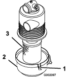
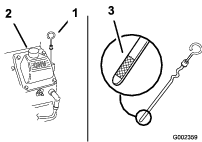
Servicing the Carbon Canister
Replacing the Carbon Canister Air Filter
| Maintenance Service Interval | Maintenance Procedure |
|---|---|
| Every 200 hours |
|
-
Shut off the engine, remove the key, and wait for all moving parts to stop before leaving the operating position.
-
Remove and discard the carbon canister air filter (Figure 17).
-
Install the new air filter.
Replacing the Carbon Canister Purge-line Filter
| Maintenance Service Interval | Maintenance Procedure |
|---|---|
| Every 200 hours |
|
Note: Check the purge-line filter occasionally for dirt. If the filter appears to be dirty, replace it.
-
Stop the engine, remove the key, and wait for all moving parts to stop before leaving the operating position.
-
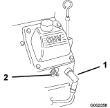
Move the spring-type hose clamps on both sides of the carbon canister purge-line filter away from the filter (Figure 18).
-
Remove and discard the carbon filter (Figure 18).
-
Install a new filter into the hose with the arrow on the filter pointing toward the check valve and secure it with the hose clamps (Figure 18).
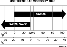
Servicing the Engine Oil
Note: Change the oil more frequently when the operating conditions are extremely dusty or sandy.
Oil Type: Detergent oil (API service SG, SH, SJ or higher)
Crankcase Capacity: w/filter, 2 L (67 oz)
Viscosity: See the table below.
Checking the Engine-Oil Level
| Maintenance Service Interval | Maintenance Procedure |
|---|---|
| Before each use or daily |
|
Note: The best time to check the engine oil is when the engine is cool before it has been started for the day. If it has already been run, allow the oil to drain back down to the sump for at least 10 minutes before checking. If the oil level is at or below the ADD mark on the dipstick, add oil to bring the oil level to the FULL mark. Do not overfill. If the oil level is between the FULL and ADD marks, no oil addition is required.
-
Park the machine on a level surface.
-
Shut off the engine, remove the key, and wait for all moving parts to stop before leaving the operating position.
-
Clean around the oil dipstick (Figure 20) so that dirt cannot fall into the filler hole and damage the engine.
-
Unscrew the oil dipstick and wipe the end clean (Figure 20).
-
Slide the oil dipstick fully into the filler tube, but do not thread it onto the tube (Figure 20).
-
Pull the dipstick out and look at the metal end. If the oil level is low, slowly pour only enough oil into the filler tube to raise the level to the FULL mark.
Important: Do not overfill the crankcase with oil and run the engine. Engine damage can result.
Changing the Oil
| Maintenance Service Interval | Maintenance Procedure |
|---|---|
| Every 100 hours |
|
-
Start the engine and let it run 5 minutes. This warms the oil so it drains better.
-
Park the machine so that the drain side is slightly lower than the opposite side to ensure the oil drains completely.
-
Shut off the engine, remove the key, and wait for all moving parts to stop before leaving the operating position.
-
Place a pan below the drain. Rotate the oil-drain valve to allow the oil to drain (Figure 21).
Note: A hose may be inserted onto the drain valve to direct the oil flow. The hose is not included with the machine.
-
When the oil has drained completely, close the drain valve.
Note: Dispose of the used oil at a recycling center.
-
Slowly pour approximately 80% of the specified oil into the filler tube (Figure 20).
-
Check the oil level; refer to Checking the Engine-Oil Level.
-
Slowly add the additional oil to bring it to the FULL mark.
Changing the Oil Filter
| Maintenance Service Interval | Maintenance Procedure |
|---|---|
| Every 200 hours |
|
Note: Change the oil filter more frequently when the operating conditions are extremely dusty or sandy.
-
Drain the oil from the engine; refer to Changing the Oil.
-
Remove the old filter and wipe the filler adapter gasket surface (Figure 22).
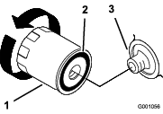
-
Apply a thin coat of new oil to the rubber gasket on the replacement filter (Figure 22).
-
Install the replacement oil filter to the filter adapter, turn the oil filter clockwise until the rubber gasket contacts the filter adapter, then tighten the filter an additional 2/3 to 1 turn (Figure 22).
-
Fill the crankcase with the proper type of new oil; refer to Changing the Oil.
-
Run the engine for about 3 minutes, stop the engine, and check for oil leaks around the oil filter.
-
Check the engine oil level and add oil if needed.
Servicing the Spark Plugs
Ensure that the air gap between the center and side electrodes is correct before installing the spark plugs. Use a spark plug wrench for removing and installing the spark plugs and a gapping tool/feeler gauge to check and adjust the air gap. Install new sparks plugs if necessary.
Type: Champion® RC12YC, Champion® Platinum 3071 or equivalent
Air Gap: 0.76 mm (0.030 inch)
Checking the Spark Plugs
| Maintenance Service Interval | Maintenance Procedure |
|---|---|
| Every 200 hours |
|
-
Look at the center of the spark plugs (Figure 23). If you see light brown or gray on the insulator, the engine is operating properly. A black coating on the insulator usually means that the air cleaner is dirty.
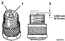
Important: Always replace a spark plug when it has a black coating, worn electrodes, an oily film, or cracks.
-
Check the gap between the center and side electrodes (Figure 23). Bend the side electrode (Figure 23) if the gap is not correct.
Removing the Spark Plugs
-
Stop the engine, remove the key, and wait for all moving parts to stop before leaving the operating position.
-
Disconnect the wires from the spark plugs (Figure 24).
-
Clean around the spark plugs to prevent dirt from falling into the engine and potentially causing damage.
-
Remove the spark plugs and the metal washers.
Installing the Spark Plugs
-
Install the spark plugs and the metal washer. Ensure that the air gap is set correctly.
-
Tighten the spark plugs to 24.4 to 29.8 N⋅m (18 to 22 ft-lb).
-
Connect the wires to the spark plugs (Figure 23).
Cleaning the Engine Screen and the Oil Cooler
| Maintenance Service Interval | Maintenance Procedure |
|---|---|
| Before each use or daily |
|
Before each use, check and clean the engine screen and oil cooler. Remove any build up of grass, dirt or other debris from the oil cooler and engine screen (Figure 25).

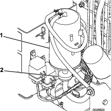
Fuel System Maintenance
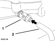
Replacing the Fuel Filter
| Maintenance Service Interval | Maintenance Procedure |
|---|---|
| Every 500 hours |
|
Never install a dirty filter if it is removed from the fuel line.
-
Stop the engine, remove the key, and wait for all moving parts to stop before leaving the operating position.
-
Allow the machine to cool down.
-
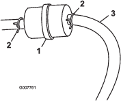
Squeeze the ends of the hose clamps together and slide them away from the filter (Figure 26).
-
Remove the filter from the fuel lines.
-
Install a new filter and move the hose clamps close to the filter (Figure 26).
Servicing the Fuel Tank
Danger
In certain conditions, fuel is extremely flammable and highly explosive. A fire or explosion from fuel can burn you and others and can damage property.
-
Drain fuel from the fuel tank when the engine is cold. Do this outdoors in an open area. Wipe up any fuel that spills.
-
Never smoke when draining fuel, and stay away from an open flame or where a spark may ignite the fuel fumes.
-
Park the machine on a level surface to ensure that the fuel tanks drain completely.
-
Shut off the engine, remove the key, and wait for all moving parts to stop before leaving the operating position.
-
Loosen the hose clamp at the fuel filter and slide it up the fuel line away from the fuel filter (Figure 26).
-
Disconnect the fuel line from the fuel filter (Figure 26).
Note: Allow fuel to drain into a fuel container can or drain pan (Figure 26).
Note: This is the best time to install a new fuel filter because the fuel tank is empty.
-
Install the fuel line onto the fuel filter. Slide the hose clamp close to the fuel filter to secure the fuel line (Figure 26).
Electrical System Maintenance
Important: Before welding on the machine, disconnect the controller and the negative cable from the battery to prevent damage to the electrical system.
Electrical System Safety
-
Disconnect the battery before repairing the machine. Disconnect the negative terminal first and the positive last. Connect the positive terminal first and the negative last.
-
Charge the battery in an open, well-ventilated area, away from sparks and flames. Unplug the charger before connecting or disconnecting the battery. Wear protective clothing and use insulated tools.
Replacing the Remote Batteries
The handheld remote is powered by 4 AAA batteries. When installing batteries, be sure to observe proper polarity as marked on the inside of the compartment to avoid damaging the unit. To replace or install batteries in the remote control:
-
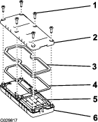
Remove the 6 screws from the back of the remote and remove the cover (Figure 27).
Note: If possible, leave the rubber seal and steel gasket in the channel when removing the cover and batteries.
-
Remove the discharged batteries and properly dispose in accordance with local regulations.
-
Plug each fresh battery into a terminal cradle observing proper polarity.
Note: If the batteries are improperly installed, the machine will not be damaged but will fail to operate.
-
If you accidentally removed the rubber seal and the steel gasket, replace them carefully into the channel in the handheld remote.
-
Replace the cover and secure it with the 6 screws removed previously (Figure 27) and torque them to 1.5 to 1.7 N∙m (13 to 15 in-lb).
Drive System Maintenance
Inspecting the Tires
| Maintenance Service Interval | Maintenance Procedure |
|---|---|
| Every 100 hours |
|
Check the tire pressure frequently to ensure proper inflation (241 kPa (35 psi). If the tires are not inflated to the correct pressure, the tires will wear prematurely.
Operating accidents can damage a tire or rim, so inspect the tire condition after an accident.
The DOT tire information is located on the side of each tire. This information gives load and speed ratings. Replacement tires should have the same or better ratings.
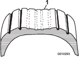
is an example of tire wear caused by under inflation.

is an example of tire wear caused by over inflation.
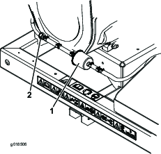
Belt Maintenance
Adjusting the Belt
| Maintenance Service Interval | Maintenance Procedure |
|---|---|
| After the first 8 hours |
|
| Every 50 hours |
|
If the belt slips when changing the direction of the blower nozzle, an adjustment to the belt is required.
-
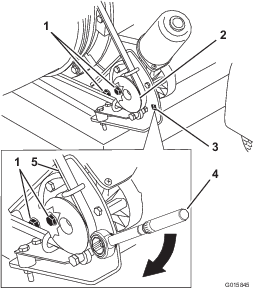
Loosen the bolts securing the pulley mounting bracket to the blower frame (Figure 32).
-
Position a torque wrench into the pulley mounting bracket (Figure 32).
-
Pivot the pulley mounting bracket away from the blower nozzle until the torque wrench reads 22.6 to 26.0 N∙m (200 to 230 in-lb) (Figure 32).
-
Tighten the mounting bolts.
Miscellaneous Maintenance
Checking the Blower Nozzle
| Maintenance Service Interval | Maintenance Procedure |
|---|---|
| Before each use or daily |
|
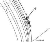
Checking the Blower Nozzle Clamp
Check the blower nozzle clamp (Figure 33) daily to assure it is tight. If the blower nozzle is dragged over obstacles or through low areas in the terrain it could be knocked loose from the clamp. Torque the clamp fasteners to 5.1 to 5.7 N∙m (45 to 50 in-lb).
Cleaning the Nozzle Guides
Check and remove any grass, dirt or debris buildup around and in between the nozzle guides (Figure 34). If the nozzle guides are not keep free of debris, the nozzle may not rotate freely, which could cause the motor to stall.
Associating the Remote Control and the Base Unit
Important: Read the entire procedure before you attempt the association process.
The remote control must establish communications with the base unit before the system can be used. The remote control is associated to the system base unit before leaving the factory. This is done using the associate procedure. In situations where it is necessary to re-establish remote control-to-base unit communications (example: introducing a new or spare remote control to an existing base unit or changing the signal frequency due to local interference issues), do the following steps.
Only a Pro Force remote control can be associated to a Pro Force base unit. Associating a Pro Force remote control to a different Pro Force base unit disassociates that remote control from the original base unit.
Note: Local interference may disassociate the wireless remote from the base unit during operation. Since the base unit selects the best of numerous signal frequencies during the association process, move the machine to the area of signal disruption or disassociation and perform the association procedure for best results.
-
Remove power from the base unit.
-
Stand near the base unit in unobstructed, clear line-of-sight with the remote control in hand.
-
Simultaneously press and hold the ROTATE RIGHT and ROTATE LEFT buttons. The LED will blink about once per second.
-
Continue to hold both buttons until the LED begins blinking about twice per second.
-
Release the buttons.
-
Press and hold the ROTATE LEFT button. The LED will blink about twice per second.
-
Continue holding the ROTATE LEFT button and turn the key start to the RUN position. The LED turns solid if the procedure is successful.
Note: This could take up to 20 seconds.
-
Release the ROTATE LEFT button.
The system is ready for use with that particular remote control.
Storage
Storing the Machine
-
Park the machine on a level surface, shut off the engine, remove the spark plug wire, and remove the key from the ignition.
-
Remove grass clippings, dirt, and grime from the external parts of the entire machine, especially the engine. Clean dirt and chaff from the outside of the engine cylinder head fins and blower housing.
Important: You can wash the machine with mild detergent and water. Do not pressure wash the machine. Avoid excessive use of water.
-
Service the air cleaner; refer to Servicing the Air Cleaner.
-
Change the crankcase oil; refer to Changing the Oil.
-
Check the tire pressure; refer to Checking the Tire Pressure.
-
Prepare the machine for storage when non-use occurs over 30 days. Prepare machine for storage as follows:
-
Add a petroleum based stabilizer/conditioner to fuel in the tank. Follow mixing instructions from stabilizer manufacture. Do not use an alcohol based stabilizer (ethanol or methanol).
Note: A fuel stabilizer/conditioner is most effective when mixed with fresh fuel and used at all times.
-
Run the engine to distribute conditioned fuel through the fuel system (5 minutes).
-
Stop the engine, allow it to cool, and drain the fuel tank; refer to Servicing the Fuel Tank.
-
Start the engine and run it until it stops.
-
Choke the engine. Start and run the engine until it does not start.
-
Dispose of fuel properly. Recycle according to local codes.
Important: Do not store fuel containing stabilizer/conditioner longer than the duration recommended by the fuel-stabilizer manufacturer.
-
-
Remove the spark plug(s) and check its condition; refer to Checking the Spark Plugs. With the spark plug(s) removed from the engine, pour 2 tablespoons of engine oil into the spark plug hole. Now use the starter to crank the engine and distribute the oil inside the cylinder. Install the spark plug(s). Do not install the wire on the spark plug(s).
-
Check and tighten all fasteners. Repair or replace any part that is damaged or missing.
-
Paint all scratched or bare metal surfaces. Paint is available from your Authorized Service Dealer.
-
Store the machine in a clean, dry garage or storage area. Remove the key from the ignition switch and keep it out of reach of children or other unauthorized users. Cover the machine to protect it and keep it clean.
Disposing of Waste
Engine oil, engine and remote control batteries are pollutants to the environment. Dispose of these according to your state and local regulations.
Troubleshooting
Checking Fault Codes
If the diagnostic light indicates that there is a system fault, refer to Diagnostic Light.
Entering Diagnostic Mode and Checking the Codes
-
Turn the key to the OFF position to turn off the power.
-
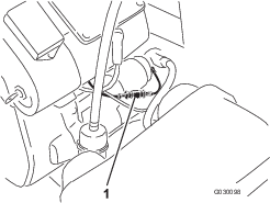
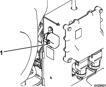
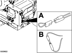
Pull the tethered cap off of the 2 diagnostic, shunt connectors (Figure 36A).
-
Connect the diagnostic, shunt connectors together (Figure 36B).
-
Turn the key to the RUN position to turn on the power.
-
Count the number of flashes to determine the fault code, then consult the following table:
Note: If there are multiple faults, both faults will flash, then a long pause, then the flash sequences will repeat.
Code LED Flash Pattern Behavior Details Machine Specific Faults 11 Blink once, pause, blink once, long pause, then repeat Lost communication with BASE. The connector is not plugged in; locate the loose or disconnected harness connector and connect it. There is a problem in the wiring; contact your authorized Toro distributor. BASE is bad; contact your authorized Toro Distributor. 12 Blink once, pause, blink twice, long pause, then repeat Version incompatibility of the BASE and/or HH The software installed is not correct. Install the correct software from TORODIAG; contact your authorized Toro Distributor. 13 Blink once, pause, blink 3 times, long pause, then repeat Wrong HH—not implemented on Rev A Wrong product association (e.g., trying to update software on a MH-400 with a ProPass handheld) 14 Blink once, pause, blink 4 times, long pause, then repeat ETR dropped due to low oil pressure. The oil pressure is low; check the oil. If it continues, the oil pressure switch may be damaged. 15 Blink once, pause, blink 5 times, long pause, then repeat ETR dropped due to low voltage. The voltage regulator or alternator is bad; contact your authorized Toro distributor.
Resetting the Fault Codes
After solving the problem, set the ignition key to the RUN position and then disconnect and reconnect the diagnostic connectors. The diagnostic light will flash continuously once per second.
Exiting Diagnostic Mode
-
Turn the key to the OFF position to turn off the power.
-
Disconnect the diagnostic, shunt connectors.
-
Push the tethered cap onto the 2 diagnostic, shunt connectors.