This product complies with all relevant European directives. For details, please see the Declaration of Incorporation (DOI) at the back of this publication
Safety
Safety Alert Symbol
This Safety Alert Symbol (Figure 1) is used both in this manual and on the machine to identify important safety messages which must be followed to avoid accidents.
This symbol means: ATTENTION! BECOME ALERT! YOUR SAFETY IS INVOLVED!

The safety alert symbol appears above information which alerts you to unsafe actions or situations and will be followed by the word DANGER, WARNING, or CAUTION.
DANGER: Indicates an imminently hazardous situation which, if not avoided, Will result in death or serious injury.
WARNING: Indicates a potentially hazardous situation which, if not avoided, Could result in death or serious injury.
CAUTION: Indicates a potentially hazardous situation which, if not avoided, May result in minor or moderate injury.
This manual uses two other words to highlight information. Important calls attention to special mechanical information and Note emphasizes general information worthy of special attention.
Maintenance Safety
Note: Determine the left and right sides of the machine from the normal operating position.
Warning
If you leave the wire on the spark plug, someone could accidentally start the engine. Accidental starting of the engine could seriously injure you or other bystanders.
Disconnect the wire from the spark plug before you do any maintenance. Set the wire aside so that it does not accidentally contact the spark plug.
Caution
Chemicals are hazardous and can cause personal injury.
-
Read the directions on the chemical labels before handling the chemicals and follow all manufacturer recommendations and precautions.
-
Keep chemicals away from your skin. Should contact occur, wash the affected area thoroughly with soap and clean water.
-
Wear goggles, gloves, and any other protective equipment recommended by the chemical manufacturer.
Important: Make sure that you wear the appropriate Personal Protective Equipment (PPE) and follow all safety precautions as stated in the Operator’s manual for your machine, before starting these instructions.
Note: Park the unit on a level surface and shut off the engine. Make sure that all moving parts have stopped, engage the parking brake, and remove the spark plug wire. Allow machine to cool before starting these installation instructions.
Installation
Preparing the Machine
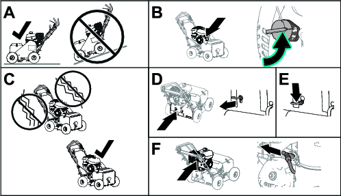
Park the machine on a level surface, shut off the engine, wait for all moving parts to stop, and remove the spark-plug wire.
Preparing the Belt Guard
Parts needed for this procedure:
| Retaining ring | 4 |
| Guard plate | 1 |
| Flange-head capscrew (5/16 x 1 inch) | 2 |
Removing the Belt Guard
Assembling the Capscrews and Spacers to the Belt Guard
-
Assemble the capscrew and spacer that you removed in Removing the Belt Guard through the hole in the belt guard as shown in Figure 5.
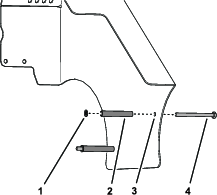
-
Secure the capscrew and spacer to the belt guard with a retaining ring (Figure 5).
-
Repeat steps 1 and 2 for the other capscrew, spacer, and retaining ring.
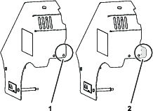
Identifying the Belt Guard
Look at the belt guard for your machine to determine if it is an old style belt guard or a new style belt guard; refer to Figure 6.
Note: A new style belt guard has a tab at the rear corner of the guard.
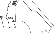
Assembling the Guard Plate
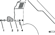
Assembling the Flange-head Capscrews
-
Assemble the flange head screw that you removed in Removing the Belt Guard through the hole in the belt guard as shown in Figure 8.
-
Secure the bolt to the guard with a retaining ring (Figure 8).
-
Repeat steps 1 and 2 for the other capscrew (Figure 8).
Replacing the Wire Harness
Parts needed for this procedure:
| Wire harness | 1 |
| Cable tie | 2 |
| Edge clip/cable tie | 1 |
Removing the Wire Harness from the Chassis
-
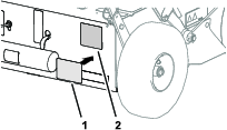
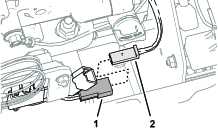
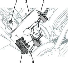
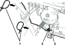
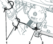
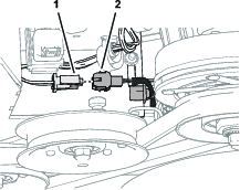
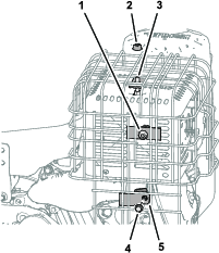
Remove the 2-socket connector for the machine wire harness from the 2-pin connector of the voltage-regulator harness (Figure 1).
-
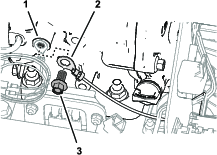
Remove the flange-head bolt that secures the ring terminal of the wire harness to the engine, and separate the ring terminal (Figure 10).
-
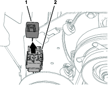
Remove the relay from the 5-socket connector of the wire harness (Figure 11).
Note: Retain the relay for installation.
-
Remove the flange head bolt and flange locknut that secure the 5-socket connector of the wire harness to the inboard belt guard (Figure 12).
-
Remove the 2 push-in harness clips that secure the wire harness to the belt guard (Figure 12).
-
Remove the 2 socket connector of the wire harness from the belt clutch connector (Figure 13).
-
Remove the push-in harness clip securing the harness to the clutch-stop bracket (Figure 13).
Removing the Wire Harness from the Handlebar
-
Remove the push-in harness clip securing the harness to the spring bracket (Figure 14).
-
Remove the 2 cable ties that secure the wire harness to lower handle-bar tube (Figure 14).
-
Remove the 2 socket connector of the wire harness from the bail switch (Figure 15).

-
Remove the push-in harness clip that secure the wire harness to the switch bracket of the handle bar (Figure 15).
-
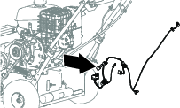
Remove the wire harness from the machine (Figure 16).
Note: Discard the old wire harness.
Installing the CE Wire Harness at the Handlebar
-
Plug the 2 socket connector of the CE wire harness into the bail switch (Figure 17).
Note: The connector for the bail switch is at the end of the harness furthest from the other connectors.
-
Insert the push-in harness clip of the wire harness into hole in the switch bracket (Figure 17).
-
Route the wire harness along the lower handle bar tube.
-
Insert the push-in harness clip of the wire harness into hole in the spring bracket (Figure 18).
-
Secure the wire harness to the loser handlebar tube with 2 cable ties (Figure 18).
Routing and Connecting the Wire Harness and to the Belt Clutch
-
Route the with harness under the clutch-stop bracket and toward the front of the machine (Figure 19).
-
Insert the 2 socket connector of the wire harness into the belt clutch connector (Figure 19).
-
Insert the push-in harness clip securing of the harness in to the hole in the clutch-stop bracket (Figure 19).
Installing the CE Wire Harness at the Inboard Belt Guard
-
Insert the 2 push-in harness clips of the wire harness into the 2 holes 6 mm (1/4 inch) in the belt guard as shown in Figure 20.
-
Install the 5-socket connector of the wire harness to the inboard belt guard (Figure 20) with the flange head bolt and flange locknut that you removed in Removing the Wire Harness from the Chassis.
-
Insert the relay into the 5-socket connector of the wire harness (Figure 21).
-
Assemble the edge clip/cable tie to the frame plate as shown in Figure 23.
Routing and Connecting the Wire Harness to the Engine
-
Rout the branch of the wire harness with the ring terminal and the 2-socket connector toward the front of the engine.
-
Assemble the ring terminal of the wire harness to the engine (Figure 23) with the flange-head bolt that you removed in Removing the Wire Harness from the Chassis.
-
Insert the 2-pin connector of the voltage-regulator harness into the 2-socket connector for the machine wire harness (Figure 24).
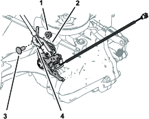
Installing the Transmission Return and Neutral Arms
Parts needed for this procedure:
| Torx-head screw | 1 |
| Lower return arm | 1 |
| Upper return arm | 1 |
| Neutral arm and reverse switch | 1 |
Removing the Bidirectional and Return-Control Arms
-
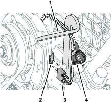
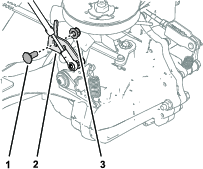
Remove the flange locknut and carriage bolt that secure the transaxle bracket to the return-control arm (Figure 25).
-
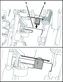
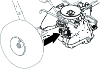
Remove the screw (5/16 x 3/4 inch) that secures the bushing to the transmission housing, and remove the bushing (Figure 26).
-
Remove the spring from the upper and lower bidirectional arms (Figure 26).
-
Remove the screw (5/16 x 1 inch) that secures the upper and lower bidirectional arms, and return-control arm to the transmission housing, and remove the arms (Figure 26).
Note: Discard the upper and lower bidirectional arms.
Installing the Upper and Lower Return Arm and the Neutral Arm
-
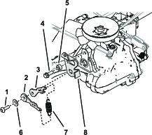
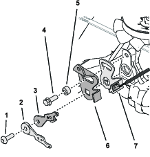
Assemble the upper return arm, lower return arm, return-control arm, and neutral arm and reverse switch to the transmission housing with the torx-head screw as shown in Figure 27.
-
Install the screw (5/16 x 3/4 inch) and bushing to the transmission housing as shown in Figure 27.
-
Assemble the transaxle bracket onto the return control arm with the carriage bolt and flange locknut (Figure 28).
-
Assemble the spring onto the hooks of the upper and lower return arms (Figure 29).

Routing and Connecting the Transmission Reverse Switch
Parts needed for this procedure:
-
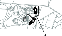
Route the wire harness of the transmission reverse switch toward the left side of the machine and up (Figure 30).
-
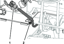
Route the wire harness along the edge clip/cable tie, and secure the wire harness with the cable tie (Figure 31).
-
Plug the 2-pin connector of the reverse switch harness into the 2-socket connector of the wire harness from the kit (Figure 32).
Replacing the Exhaust Guard
Parts needed for this procedure:
| Exhaust guard | 1 |
Removing the Exhaust Guard
-
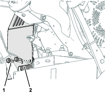
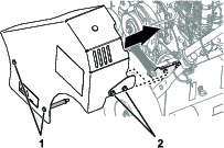
Loosen the flange nut at the inboard side of the exhaust guard (Figure 33).
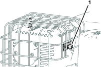
-
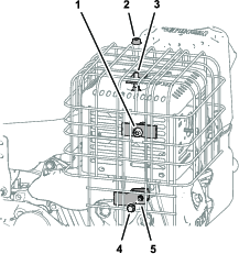
Remove the flange nut that secure the exhaust guard to the stud at the top of the muffler (Figure 34).
-
Loosen the flange nut at the outboard side of the of the exhaust guard (Figure 34).
-
Remove the flange head bolt that secure the exhaust guard mount on the exhaust duct (Figure 34).
-
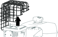
Remove the exhaust guard from the machine (Figure 35).
Note: Discard the old exhaust guard.
Installing the CE Exhaust guard
-
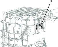
Align the mounting tabs of the CE exhaust guard over the studs of the muffler (Figure 37).
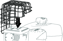
-
Loosely assemble the exhaust to the guard mount on the exhaust duct with the flange head bolt (Figure 38).
-
Assemble the flange nut that secures the exhaust guard to the stud at the top of the muffler (Figure 38).
-
Tighten the flange nuts and flange-head bolt at the inboard, top, and outboard side of the exhaust guard.
Installing the Belt Guard
-
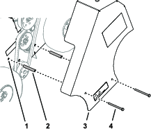
Align the belt guard, capscrews, and flange-head bolts with the holes in the side frame plate and the spring bracket (Figure 39).
-
Assemble the belt guard to the machine with the 2 capscrews, and 2 flange-head bolts (Figure 39).
-
Torque the capscrews and flange-head bolts to 1378 to 2542 N∙cm (175 to 225 in-lb).
Installing the Decals
Parts needed for this procedure:
| Decal (machine production date) | 1 |
| Decal (sound) | 1 |