


Maintenance
Note: Determine the left and right sides of the machine from the normal operating position.
Recommended Maintenance Schedule(s)
| Maintenance Service Interval | Maintenance Procedure |
|---|---|
| After the first 10 operating hours |
|
| After the first 50 operating hours |
|
| After the first 200 operating hours |
|
| Before each use or daily |
|
| Every 50 hours |
|
| Every 100 hours |
|
| Every 150 hours |
|
| Every 200 hours |
|
| Every 400 hours |
|
| Every 800 hours |
|
| Every 1,500 hours |
|
| Every 2 years |
|
Important: Refer to your Engine Operator's Manual for additional maintenance procedures. A detailed Service Manual is also available for purchase from your Authorized Toro Distributor.
Pre-Maintenance Procedures
Important: The fasteners on the covers of this machine are designed to remain on the cover after removal. Loosen all of the fasteners on each cover a few turns so that the cover is loose but still attached, then go back and loosen them until the cover comes free. This will prevent you from accidentally stripping the bolts free of the retainers.
Close sectionLubrication
Greasing the Bearings and Bushings
The machine has grease fittings that must be lubricated regularly with No. 2 general-purpose, lithium-based grease. If the machine is operated under normal conditions, lubricate all bearings and bushings after every 50 hours of operation. Lubricating bearings and bushings daily when operating conditions are extremely dusty and dirty. Dusty and dirty operating conditions could cause dirt to get into the bearings and bushings, resulting in accelerated wear. Lubricate the grease fittings immediately after every washing, regardless of interval specified.
-
Wipe the grease fittings clean so that foreign matter cannot be forced into the bearing or bushing.
-
Pump grease into the fittings.
-
Wipe off excess grease.
Note: Bearing life can be negatively affected by improper wash down procedures. Do not wash down the unit when it is still hot and avoid directing high-pressure or high volume spray at the bearings or seals.
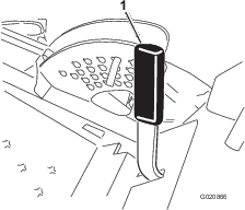
Close sectionServicing the Mower-Deck Gear Box Lubricant
The gear box is designed to operate with SAE EP90W gear lube. Although the gear box comes from the factory with lubricant, check the level of the lubricant in the cutting unit before operating it and as recommended in the Daily Maintenance Checklist.
Checking the Mower Deck Gear Box Lubricant
-
Position the machine and cutting unit on a level surface.
-
Lower the mower deck to the 2.5 cm (1 inch) height of cut.
-
Disengage the PTO, move the motion control levers to the neutral locked position, and set the parking brake.
-
Move the throttle lever to the Slow position, stop the engine, remove the key, and wait for all moving parts to stop before leaving the operating position.
-
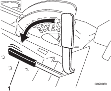
Lift the footrest, exposing the top of the mower deck.
-
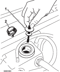
Remove the dipstick/fill plug from the top of the gear box (Figure 38) and make sure that the lubricant is between the marks on the dipstick.
-
If the lubricant level is low, add enough lubricant until the level is between the marks on the dipstick.
Note: Do not over fill gearbox; over filling the gear box may damage it.
Changing the Mower Deck Gear Box Lubricant
-
Position the machine and cutting unit on a level surface.
-
Lower the mower deck to the 2.5 cm (1 inch) height of cut.
-
Disengage the PTO, move the motion control levers to the neutral locked position, and set the parking brake.
-
Move the throttle lever to the Slow position, stop the engine, remove the key, and wait for all moving parts to stop before leaving the operating position.
-
Lift the footrest, exposing the top of the mower deck.
-
Remove the dipstick/fill plug from the top of the gear box (Figure 38).
-
Place a funnel and drain pan under the drain plug located under the front of the gear box and remove the plug, draining the lubricant into the pan.
-
Replace the drain plug.
-
Add enough lubricant, approximately 283 ml (12 oz), until the level is between the marks on the dipstick.
Note: Do not over fill gearbox; over filling the gear box may damage it.
Engine Maintenance
Checking the Air Cleaner
-
Check the air cleaner body for damage, which could possibly cause an air leak. Replace a damaged air cleaner body. Check the whole clean air intake system for leaks, damage, or loose hose clamps.
-
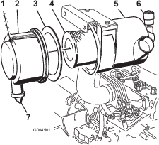
Service the air cleaner filter when the air cleaner indicator (Figure 39) shows red or every 400 hours (more frequently in extremely dusty or dirty conditions). Do not over service the air filter.
-
Be sure the cover is seated correctly and seals with the air cleaner body.
Servicing the Air Cleaner
-
Pull the latch outward and rotate the air-cleaner cover counter-clockwise (Figure 39).
-
Remove the cover from the air-cleaner body (Figure 39).
-
Before removing the filter, use low pressure air (40 psi, clean and dry) to help remove large accumulations of debris packed between outside of primary filter and the canister.
This cleaning process prevents debris from migrating into the intake when the primary filter is removed.
Important: Avoid using high-pressure air which could force dirt through the filter into the intake tract.
-
Remove and replace the primary filter (Figure 39).
Important: Do not clean the used element to avoid damage to the filter media.
-
Inspect the new filter for shipping damage, checking the sealing end of the filter and the body.
Important: Do not use a damaged element.
-
Ensure that the foam gasket is in place in the cover and that it is not torn or damaged (Figure 39).
Note: If it is damaged, replace it.
-
Insert the new filter by applying pressure to the outer rim of the element to seat it in the canister.
Important: Do not apply pressure to the flexible center of the filter.
-
Clean the dirt ejection port (located in the removable cover) as follows:
-
Remove the rubber outlet valve from the cover (Figure 39).
-
Clean the cavity.
-
Replace the outlet valve.
-
-
Install the cover orienting the rubber outlet valve in a downward position—between approximately 5:00 to 7:00 when viewed from the end.
-
Reset the indicator (Figure 39) if showing red.
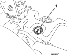
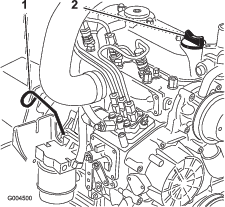
Servicing the Engine-Oil
Checking the Engine-Oil Level
The engine is shipped with oil in the crankcase; however, the oil level must be checked before and after the engine is first started. Check oil level before each day's operation or each time you use the machine.
The crankcase capacity is approximately 3.8liters (4quarts) with the filter. Use high-quality engine oil that meets the following specifications:
-
API Classification Level Required: CH-4, CI-4 or higher.
-
Preferred oil: SAE 15W-40 (above 0°F (-17°C)
-
Alternate oil: SAE 10W-30 or 5W-30 (all temperatures)
Note: Toro Premium Engine oil is available from your distributor in either 15W-40 or 10W-30 viscosity. See the parts catalog for part numbers.
-
Park the machine on a level surface, lower the mower deck, move the throttle lever to the Slow position, stop the engine, and remove the key from the ignition switch.
-
Open the hood.
-
Remove the dipstick (Figure 40), wipe it clean, and install the dipstick. Remove the dipstick and check the oil level.
The oil level should be up to the Full mark on the dipstick.
-
If the oil level is below the Full mark, remove the fill cap (Figure 40) and add oil until the level reaches the Full mark on the dipstick.
Important: Do not overfill.
Note: Use a clean funnel to prevent spills.
-
Install the oil fill cap.
-
Close the hood.
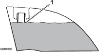
Changing the Engine Oil And Filter
Change the oil and filter initially after first 50 hours of operation and then every 150 hours of operation thereafter. If possible, run the engine just before changing the oil because warm oil flows better and carries more contaminants than cold oil.
-
Position the machine on a level surface.
-
Open the hood.
-
Set a drain pan under the oil pan and in line with the drain plug (Figure 41).
-
Clean the area around the drain plug.
-
Remove the drain plug and allow the oil to flow into drain pan.
-
Remove and replace the oil filter (Figure 41).
-
After the oil is drained, install the drain plug and wipe up any oil that is spilled.
-
Fill the crankcase with oil; refer to Checking the Engine Oil Level.
Fuel System Maintenance
Danger
Under certain conditions, diesel fuel and fuel vapors are highly flammable and explosive. A fire or explosion from fuel can burn you and others and can cause property damage.
-
Use a funnel and fill the fuel tank outdoors, in an open area, when the engine is off and is cold. Wipe up any fuel that spills.
-
Do not fill the fuel tank completely full. Add fuel to the fuel tank until the level is to the bottom of the filler neck.
-
Never smoke when handling fuel, and stay away from an open flame or where fuel fumes may be ignited by a spark.
-
Store fuel in a clean, safety-approved container and keep the cap in place.
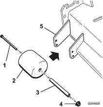
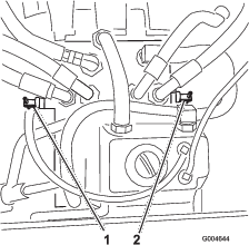
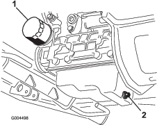
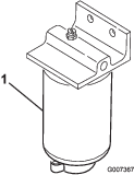
Servicing the Water Separator
Drain water or other contaminants from water separator (Figure 42) daily.
-
Place a clean container under the fuel filter.
-
Loosen the drain plug on the bottom of the filter canister.
-
Clean the area where the filter canister mounts.
-
Remove the filter canister and clean the mounting surface.
-
Lubricate the gasket on the filter canister with clean oil.
-
Install the filter canister by hand until the gasket contacts mounting surface, then rotate it an additional 1/2 turn.
-
Tighten the drain plug on the bottom of the filter canister.
Cleaning the Fuel Tank
Drain and clean fuel tank every 2 years. Also, remove and clean the in-line strainers after draining the tank. Use clean diesel fuel to flush out the tank.
Important: Drain and clean the tank if the fuel system becomes contaminated or if the machine is to be stored for an extended period.
Close sectionFuel Lines and Connections
Check the fuel lines and connections. Inspect them for deterioration, damage, chaffing, or loose connections.
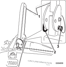
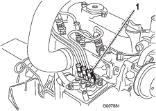
Close sectionBleeding the Fuel System
-
Park the machine on a level surface. Ensure that the fuel tank is at least half full.
-
Unlatch and raise the hood.
-
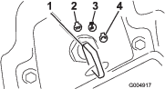
Place a rag under the air-bleed screw on the fuel-injection pump and open it (Figure 43).
-
Turn the key in the ignition switch to the On position.
The electric fuel pump will begin operation, thereby forcing air out around the air bleed screw.
Caution
The engine may start during this procedure. Moving fans and belts in a running engine can severely injure you or bystanders.
Keep hands, fingers, loose clothing/jewelry, and hair away from the engine fan and belt during this procedure.
-
Leave the key in the On position until a solid stream of fuel flows out around the screw.
-
Tighten the screw and turn key to the Off position.
Note: Normally, the engine should start after above bleeding procedures are followed. However, if engine does not start, air may be trapped between injection pump and injectors; refer to Bleeding Air from the Injectors.
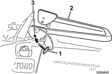
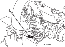
Bleeding Air from the Injectors
Note: Use this procedure only if the fuel system has been purged of air through normal priming procedures and engine will not start; refer to Bleeding the Fuel System.
-
Place a rag under the pipe connection coming from the injection pump to the No. 1 injector nozzle as illustrated in Figure 44.
-
Move the throttle to the Fast position.
-
Turn the ignition key the Start position, and watch the fuel flow around the connector.
Caution
The engine may start during this procedure. Moving fans and belts in a running engine can severely injure you or bystanders.
Keep hands, fingers, loose clothing/jewelry, and hair away from the engine fan and belt during this procedure.
-
Tighten the pipe connector securely when it attains a solid flow.
-
Turn the key to the Off position.
-
Repeat this procedure for the remaining nozzles.
Electrical System Maintenance
Important: Whenever working with the electrical system, always disconnect the battery cables, negative (-) cable first, to prevent possible wiring damage from short-outs.
Servicing the Battery
Warning
Battery posts, terminals, and related accessories contain lead and lead compounds, chemicals known to the State of California to cause cancer and reproductive harm. Wash hands after handling.
Keep the top of the battery clean. If you store the machine in a location where temperatures are extremely high, the battery will run down more rapidly than if the machine is stored in a location where the temperature is cool.
Keep the top of the battery clean by washing it periodically with a brush dipped in ammonia or bicarbonate of soda solution. Flush the top surface with water after cleaning it. Do not remove the fill caps while cleaning the battery.
The battery cables must be tight on the terminals to provide good electrical contact.
If corrosion occurs at the terminals, disconnect the cables, negative (-) cable first, and scrape the clamps and terminals separately. Connect the cables, positive (+) cable first, and coat the terminals with petroleum jelly.
Warning
Battery terminals or metal tools could short against metal machine components causing sparks. Sparks can cause the battery gasses to explode, resulting in personal injury.
-
When removing or installing the battery, do not allow the battery terminals to touch any metal parts of the machine.
-
Do not allow metal tools to short between the battery terminals and metal parts of the machine.
Warning
Incorrect battery cable routing could damage the machine and cables causing sparks. Sparks can cause the battery gasses to explode, resulting in personal injury.
-
Always disconnect the negative (black) battery cable before disconnecting the positive (red) cable.
-
Always connect the positive (red) battery cable before connecting the negative (black) cable.
Storing the Battery
If the machine will be stored more than 30 days, remove the battery and charge it fully. Either store it on a shelf or on the machine. Leave the cables disconnected if it is stored on the machine. Store the battery in a cool environment to prevent the battery from discharging rapidly. To prevent the battery from freezing, make sure it is fully charged. The specific gravity of a fully charged battery is 1.265 to 1.299.
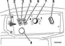
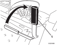
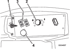
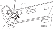
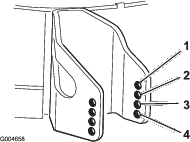
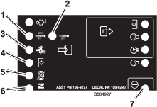
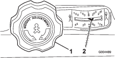
Close sectionChecking the Fuses
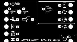
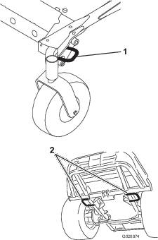
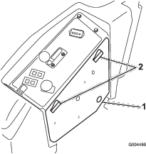
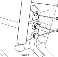
The fuses are located under the control panel. Access them through the side panel cover (Figure 45). To open the side panel cover, release the 2 latches and pull out on it.
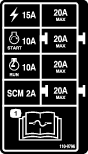
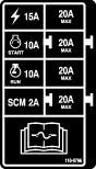
If the machine stops or has other electrical system issues, check the fuses. Grasp each fuse in turn and remove them one at a time, checking to see if any are blown. If you need to replace a fuse, always use the same type and amperage rated fuse as the one you are replacing, otherwise you could damage the electrical system (refer to the decal next to the fuses (Figure 46) for a diagram of each fuse and its amperage).
Note: If a fuse blows frequently, you probably have a short in the electrical system and should have it serviced by a qualified service technician.
Drive System Maintenance
Checking the Tire Pressure
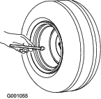
Check the pressure after every 50operating hours or monthly, whichever occurs first (Figure 47).
Maintain the air pressure in the front and rear tires. The correct air pressure is 124 kPa (18 psi) in the rear tires and 172 kPa (25 psi) in the caster wheels. Uneven tire pressure can cause an uneven cut. Check the tires when they are cold to get the most accurate pressure reading.
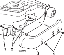
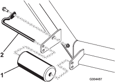
Replacing the Caster Wheels and Bearings
-
Obtain a new caster wheel assembly, cone bearings, and bearing seals from your Authorized Toro Distributor.
-
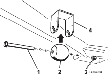
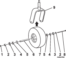
Remove the locknut from the bolt holding the caster wheel assembly between the caster fork (Figure 48).
-
Grasp the caster wheel, and slide the bolt out of the fork or pivot arm.
-
Discard the old caster wheel and bearings.
-
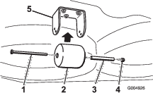
Assemble the caster wheel by pushing the cone bearings and seals, packed with grease, into the wheel hub, positioned as shown in Figure 48.
-
Slide the spacer into the wheel hub through the bearings, captivating the spacer inside the wheel hub with 2 bearing spacers.
Important: Ensure that the seal lips are not folded inward.
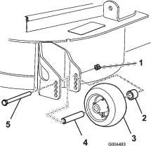
-
Install the caster-wheel assembly between the castor fork and secure it in place with the bolt and locknut.
-
Tighten the nut until the wheel no longer spins freely, then back it off just until the wheel spins freely.
-
Attach a grease gun to the grease fitting on the caster wheel and fill it with No. 2 general-purpose, lithium-based grease.
Cooling System Maintenance
Danger
Discharging hot pressurized coolant or touching hot radiator and surrounding parts can cause severe burns.
-
Do not remove the radiator cap when the engine is hot. Always allow the engine to cool at least 15minutes or until the radiator cap is cool enough to touch without burning your hand before removing the radiator cap.
-
Do not touch radiator and surrounding parts that are hot.
Danger
The rotating fan and drive belt can cause personal injury.
-
Do not operate the machine without the covers in place.
-
Keep fingers, hands and clothing clear of rotating fan and drive belt.
-
Shut off the engine and remove the ignition key before performing maintenance.
Caution
Swallowing engine coolant can cause poisoning.
-
Do not swallow engine coolant.
-
Keep out of reach from children and pets.
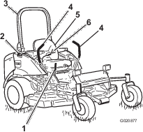
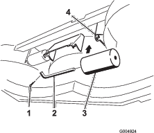
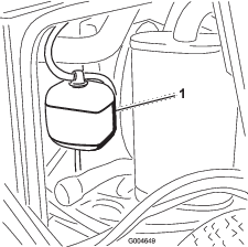
Checking the Cooling System
The cooling system is filled with a 50/50 solution of water and permanent ethylene glycol anti freeze. Check the level of the coolant in the expansion tank at the beginning of each day before starting the engine. The capacity of the cooling system is 7.5 liters (6 quarts).
-
Check the level of the coolant in the expansion tank (Figure 49). The coolant level should be between the marks on the side of the tank.
-
If coolant level is low, remove the expansion tank cap and replenish the system. Do not overfill.
-
Install the expansion tank cap.
Cleaning the Radiator
To prevent the engine from overheating, the radiator must be kept clean. Normally, check the radiator daily and, if necessary, clean any debris off these parts. However, it will be necessary to check and clean the radiator frequently in extremely dusty and dirty conditions.
Note: If the mower deck or engine shuts off due to overheating, first check the radiator for excessive buildup of debris.
Clean the radiator as follows:
-
Open the hood.
-
Working from the fan side of the radiator, blow out debris with low pressure (50 psi) compressed air (do not use water). Repeat the step from the front of the radiator and again from the fan side.
-
After the radiator is thoroughly cleaned, clean out debris that may have collected in the channel at the radiator base.
-
Close the hood.
Brake Maintenance
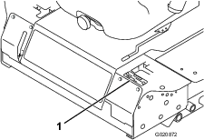
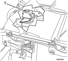
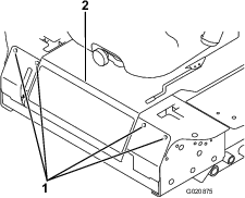
Adjusting the Parking Brake Interlock Switch
-
Stop the machine, move the deck lift switch fully into the neutral-locked position, set the parking brake, and remove the ignition key.
-
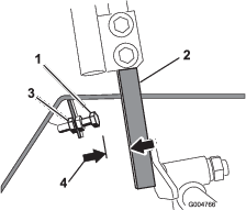
Remove the bolts securing the front panel and remove the panel (Figure 50).
-
Loosen the 2 jam nuts securing the parking brake interlock switch to the mounting bracket.
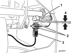
-
Move the switch up or down on the bracket until the distance between the brake shaft sensor and the switch plunger is 3.9 mm (5/32 inch) (Figure 51).
Note: Make sure that the brake-shaft sensor does not contact the switch plunger.
-
Secure the switch jam nuts.
-
Test the adjustment as follows:
-
Ensure that the parking brake is engaged and you are not sitting on the seat, then start the engine.
-
Move the control levers out of the neutral locked position.
The engine should stop. If not, recheck the adjustment you made to the switch.
-
-
Install the front panel.
Belt Maintenance
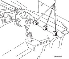
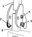
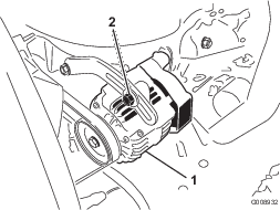
Checking the Alternator Belt
Check the condition and tension of the belts (Figure 52) after every 100 operating hours.
-
Proper tension will allow 10mm (3/8inch) deflection when a force of 44 N (10lb.) is applied on the belt midway between the pulleys.
-
If the deflection is not 10mm (3/8inch), loosen the alternator mounting bolts (Figure 52). Increase or decrease the alternator belt tension and tighten the bolts. Check the deflection of the belt again to ensure that the tension is correct.
Controls System Maintenance
Adjusting the Control Lever Neutral Interlock Switch
-
Stop the machine, move the deck lift switch fully into the neutral-locked position, set the parking brake, and remove the ignition key.
-
Remove the bolts securing the front panel and remove the panel (Figure 53).
-
Loosen the 2 screws securing the interlock switch (Figure 54).
-
Holding the control lever against the frame, move the switch toward the lever until the distance between lever and switch body is 0.4 to 1 mm (0.015 to 0.045 inch) (Figure 54).
-
Secure the switch.
-
Repeat steps 3 to 5 for the other lever.
-
Install the front panel.
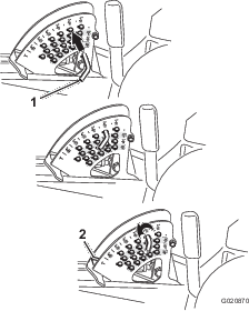
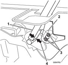
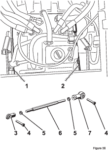
Adjusting the Control Lever Neutral Return
If the motion control levers do not align with the neutral slots when released from the reverse drive position, adjustment is required. Adjust each lever, spring, and rod separately.
-
Disengage the PTO, move the control lever to the neutral locked position, and set the parking brake.
-
Move the throttle lever to the Slow position, stop the engine, remove the key, and wait for all moving parts to stop before leaving the operating position.
-
Remove the bolts securing the front panel and remove the panel (Figure 55).
-
Move the control lever to the neutral position but not locked (Figure 57).
-
Pull the lever back until the clevis pin (on an arm above the pivot shaft) contacts the end of the slot (just beginning to put pressure on the spring) (Figure 56).
-
Check where the control lever is relative to notch in console (Figure 57).
Note: It should be centered allowing lever to pivot outward to the neutral lock position.
-
If adjustment is needed, loosen the nut and jam nut against the yoke (Figure 56).
-
Applying slight rearward pressure on the motion control lever, turn the head of the adjustment bolt in the appropriate direction until the control lever is centered in the neutral lock position (Figure 56).
Note: Keeping rearward pressure on the lever will keep the pin at the end of the slot and allow the adjustment bolt to move the lever to the appropriate position.
-
Tighten the nut and jam nut (Figure 56).
-
Repeat steps 4 through 9 for the other control lever.
-
Install the front panel.
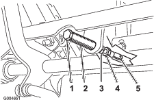
Adjusting the Traction Drive for Neutral
This adjustment must be made with drive wheels turning.
Danger
Mechanical or hydraulic jacks may fail to support the machine and cause a serious injury.
-
Use jack stands when supporting the machine.
-
Do not use hydraulic jacks.
Warning
The engine must be running to perform this adjustment. Contact with moving parts or hot surfaces may cause personal injury.
Keep hands, feet, face, clothing, and other body parts away from rotating parts, muffler, and other hot surfaces.
-
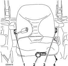
Raise the frame onto stable jack stands so that the drive wheels can rotate freely.
-
Slide seat forward, unlatch it, and swing it up and forward.
-
Disconnect the electrical connector from the seat safety switch.
-
Temporarily install a jumper wire across terminals in the wiring harness connector.
-
Start the engine, ensure that the throttle lever is midway between the Fast and Slow positions, and release the parking brake.
Note: The motion control levers must be in the neutral locked position while making any adjustments.
-
Adjust the pump rod length on one side by rotating the hex shaft, in the appropriate direction, until the corresponding wheel is still or slightly creeping in reverse (Figure 58).
-
Move the motion control lever forward and reverse, then back to neutral. The wheel must stop turning or slightly creep in reverse.
-
Move the throttle lever to the Fast position. Make sure that the wheel remains stopped or slightly creeps in reverse; adjust it if necessary.
-
Repeat steps 6 through 8 for the other side of the machine.
-
Tighten the jam nuts at the ball joints (Figure 56).
-
Move the throttle lever to the Slow position and stop the engine.
-
Remove the jumper wire from the wire harness connector and plug the connector into the seat switch.
Warning
Electrical system will not perform proper safety shut off with jumper wire installed.
-
Remove jumper wire from wire harness connector and plug connector into seat switch when adjustment is completed.
-
Never operate this unit with jumper installed and seat switch bypassed.
-
-
Lower the seat into position.
-
Remove the jack stands.
Adjusting the Maximum Ground Speed
-
Disengage the PTO, move the motion control levers to the neutral locked position, and set the parking brake.
-
Move the throttle lever to the Slow position, stop the engine, remove the key, and wait for all moving parts to stop before leaving the operating position.
-
Remove the bolts securing the front panel and remove the panel (Figure 59).
-
Loosen the jam nut on the stop bolt for one of the control levers (Figure 60).
-
Thread the stop bolt all the way in (away from the control lever).
-
Push the control lever all the way forward until it stops and hold it there.
-
Thread the stop bolt out (toward the control lever) until there is a gap of 1.5 mm (0.060 inch) between the head of the stop bolt and the control lever.
-
Tighten the jam nut to secure the stop bolt in place.
-
Repeat steps 4 through 8 for the other control lever.
-
Install the front panel.
Note: If you wish to reduce the maximum machine speed, set the speed for both control levers as directed above, then back each stop bolt out an equal amount toward the control lever until you reach the maximum speed you desire (you will likely have to test your adjustment several times). Ensure that the machine drives straight and does not turn when both control levers are pushed all the way forward. If the machine turns, you do not have the stop bolts evenly set and will need to adjust them further.
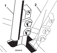
Close sectionAdjusting the Tracking
-
Disengage the PTO, move the motion control levers to the neutral locked position and set the parking brake.
-
Move the throttle lever to the Slow position, stop the engine, remove the key, and wait for all moving parts to stop before leaving the operating position.
-
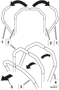
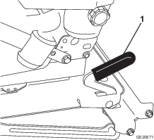
Loosen the bolts securing the control levers (Figure 61)
-
Have someone push the control-lever posts (not the control levers) all the way forward into the maximum speed position and hold them there.
-
Adjust the control levers so that they line up (Figure 62) and tighten the bolts, securing the levers to the posts.

Hydraulic System Maintenance
The reservoir is filled at the factory with approximately 4.7liters (5quarts) of high quality tractor transmission/hydraulic fluid. The recommended replacement fluid is as follows:
| Toro Premium Transmission/Hydraulic Tractor Fluid (Available in 5 gallon pails or 55 gallon drums. See parts catalog or Toro distributor for part numbers.) |
Alternate fluids: If the Toro fluid is not available, Mobil® 424 hydraulic fluid may be used.
Note: Toro will not assume responsibility for damage caused by improper substitutions.
Note: Many hydraulic fluids are almost colorless, making it difficult to spot leaks. A red dye additive for the hydraulic system oil is available in 20ml (2/3oz) bottles. One bottle is sufficient for 15-22 liters (4-6 gallons) of hydraulic oil. Order part number 44-2500 from your Authorized Toro Distributor.
Checking the Hydraulic System
Check the level of the hydraulic fluid before the engine is first started and daily thereafter.
-
Position the machine on a level surface.
-
Place the controls in the neutral locked position and start the engine.
Note: Run engine at lowest possible RPM to purge the system of air. Do not engage the PTO.
-
Raise the deck to extend lift cylinders, stop the engine, and remove the key.
-
Raise the seat to access the hydraulic fluid tank.
-
Remove the hydraulic fill cap (Figure 63) from the filler neck.
-
Remove the dipstick and wipe it with a clean rag (Figure 63).
-
Place the dipstick into the filler neck; then remove it and check level of fluid (Figure 63).
Note: If level is not within notched area of the dipstick, add enough high quality hydraulic fluid to raise level to within the notched area. Do not overfill.
-
Replace the dipstick and thread the fill cap finger-tight onto filler neck.
-
Check all hoses and fittings for leaks.
Changing the Hydraulic Oil And Filter
-
Disengage the PTO, move the motion control levers to the neutral locked position, and set the parking brake.
-
Move the throttle lever to the Slow position, stop the engine, remove the key, and wait for all moving parts to stop before leaving the operating position.
-
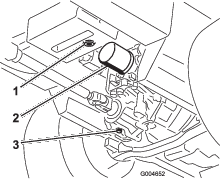
Place a large pan under the hydraulic reservoir and transmission case and remove the plugs, draining all of the hydraulic fluid (Figure 64).
-
Clean the area around the hydraulic oil filter and remove it (Figure 64).
-
Immediately install a new hydraulic oil filter.
-
Install the hydraulic reservoir and transmission case drain plugs.
-
Fill the reservoir to the proper level; refer to Hydraulic System Maintenance.
-
Start the engine and check for oil leaks. Allow the engine to run for about five minutes, then shut it off.
-
After 2 minutes, check the level of the hydraulic fluid; refer to Hydraulic System Maintenance.
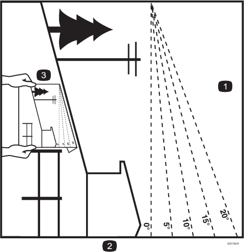
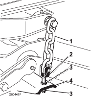
Adjusting the Mower Deck Pitch
Cutting unit pitch is the difference in height-of-cut from the front of the blade plane to the back of the blade plane. Use a blade pitch of approximately 8 mm (5/16 inch). That is the back of the blade plane is 8 mm (5/16 inch) higher than the front.
-
Position the machine on a level surface on the shop floor.
-
Set the cutting unit to the desired height-of-cut, move the throttle lever to the Slow position, stop the engine, set the parking brake, and remove the ignition key.
-
Rotate the center blade so that it points straight forward.
-
Using a short ruler, measure from the floor to the front tip of the blade.
-
Rotate the same blade tip to the rear and measure from the floor to the tip of the blade at the rear of the deck.
-
Subtract the front dimension from the rear dimension to calculate the blade pitch.
-
Adjust the jam nuts securing the rear deck yokes/chains to raise the rear of the deck so that the blade pitch is set to 8 mm (5/16 inch) (Figure 65).
Cleaning Under the Mower
Remove the grass buildup under the mower daily.
-
Disengage the PTO, move the motion control levers to the neutral locked position, and set the parking brake.
-
Move the throttle lever to the Slow position, stop the engine, remove the key, and wait for all moving parts to stop before leaving the operating position.
-
Raise the mower to the transport position.
-
Raise the front of the machine by using jack stands.
-
Thoroughly clean the underside of the mower with water.
Waste Disposal
Engine oil, batteries, hydraulic oil, and engine coolant are pollutants. Dispose of these according to your state and local regulations.
Close section