


Maintenance
Note: Determine the left and right sides of the machine from the normal operating position.
Maintenance Safety
Warning
While maintenance or adjustments are being made, someone could start the engine. Accidental starting of the engine could seriously injure you or other bystanders.
Remove the key from the ignition switch, engage parking brake, and pull the wire(s) off the spark plug(s) before you do any maintenance. Also push the wire(s) aside so it does not accidentally contact the spark plug(s).
Warning
The engine can become very hot. Touching a hot engine can cause severe burns.
Allow the engine to cool completely before service or making repairs around the engine area.
-
Park machine on level ground, disengage drives, set parking brake, stop engine, remove key or disconnect spark plug wire. Wait for all movement to stop and allow the machine to cool before adjusting, cleaning or repairing. Never allow untrained personnel to service machine.
-
Keep the machine, guards, shields and all safety devices in place and in safe working condition. Frequently check for worn or deteriorating components and replace them with the manufacturer’s recommended parts when necessary.
Warning
Removal or modification of original equipment, parts and/or accessories may alter the warranty, controllability, and safety of the machine. Unauthorized modifications to the original equipment or failure to use original Exmark parts could lead to serious injury or death. Unauthorized changes to the machine, engine, fuel or venting system, may violate applicable safety standards such as: ANSI, OSHA and NFPA and/or government regulations such as EPA and CARB.
-
Use care when checking blades. Wrap the blade(s) or wear gloves, and use caution when servicing them. Only replace damaged blades. Never straighten or weld them.
-
Use jack stands to support the machine and/or components when required.
Caution
Raising the machine for service or maintenance relying solely on mechanical or hydraulic jacks could be dangerous. The mechanical or hydraulic jacks may not be enough support or may malfunction allowing the machine to fall, which could cause injury.
Do not rely solely on mechanical or hydraulic jacks for support. Use adequate jack stands or equivalent support.
-
Carefully release pressure from components with stored energy.
-
Keep hands and feet away from moving parts. If possible, Do Not make adjustments with the engine running. If the maintenance or adjustment procedure requires the engine to be running and components moving, use extreme caution.
Warning
Contact with moving parts or hot surfaces may cause personal injury.
Keep your fingers, hands, and clothing clear of rotating components and hot surfaces.
-
Check all bolts frequently to maintain proper tightness.
Recommended Maintenance Schedule(s)
| Maintenance Service Interval | Maintenance Procedure |
|---|---|
| After the first 5 hours |
|
| Before each use or daily |
|
| Every 25 hours |
|
| Every 40 hours |
|
| Every 100 hours |
|
| Every 160 hours |
|
| Every 200 hours |
|
Periodic Maintenance
Check Engine Oil Level
| Maintenance Service Interval | Maintenance Procedure |
|---|---|
| Before each use or daily |
|
-
Stop engine and wait for all moving parts to stop. Make sure unit is on a level surface.
-
Check with engine cold.
-
Clean area around dipstick. Remove dipstick and wipe oil off. Reinsert the dipstick and push it all the way down into the tube. Do Not screw into place. Remove the dipstick and read the oil level.
-
If the oil level is low, wipe off the area around the oil fill cap, remove cap and fill to the “FULL” mark on the dipstick. Exmark 4-Cycle Premium Engine Oil is recommended; refer to the Engine Owner's manual for an appropriate API rating and viscosity. Do Not overfill.
Important: Do Not operate the engine with the oil level below the “LOW” (or “ADD”) mark on the dipstick, or over the “FULL” mark.
Check Mower Blades
| Maintenance Service Interval | Maintenance Procedure |
|---|---|
| Before each use or daily |
|
-
Stop engine, wait for all moving parts to stop, and remove key. Engage parking brake.
-
Lift deck and secure in raised position as stated in the Clean Grass Build-Up Under Deck procedure.
-
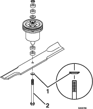
Inspect blades and sharpen or replace as required.
-
Re-install the blades (if they were removed) and torque blade bolts to 75-80 ft-lb (102-109 N-m). Be sure the spring disc washer cone is installed toward the bolt head (see Figure 8).
Replacing the Discharge Deflector
Danger
An uncovered discharge opening could allow the lawn mower to throw objects in the operator’s or bystander’s direction and result in serious injury. Also, contact with the blade could occur.
Never operate the lawn mower unless you install a mulch plate, discharge deflector, or grass collection system.
-
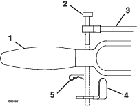
To remove a damaged or worn discharge deflector, lift the leg of the spring with the loop out of the notch in the discharge deflector and slide the rod out of the discharge deflector brackets, and discharge deflector.
-
To install new discharge deflector, orient the spring on the rod as shown in Figure 9. Slide the rod through the front discharge deflector bracket, discharge deflector, and rear deflector bracket.
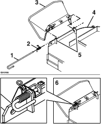
-
Hook the bent end of the rod around the front discharge deflector bracket to retain it from sliding out. Place the leg of the spring with the loop in the notch in the discharge deflector to hold the discharge deflector in the down position (see Figure 9).
Important: The discharge deflector must be spring loaded in the down position. Lift the deflector up to test that it snaps to the full down position.
Check Spark Plugs
| Maintenance Service Interval | Maintenance Procedure |
|---|---|
| Every 160 hours |
|
Remove spark plugs, check condition and reset gaps, or replace with new plugs. See Engine Owner's Manual.
Check Safety Interlock System
| Maintenance Service Interval | Maintenance Procedure |
|---|---|
| Before each use or daily |
|
Important: It is essential that operator safety mechanisms be connected and in proper operating condition prior to use.
Note: If machine does not pass any of these tests, Do Not operate. Contact your authorized EXMARK SERVICE DEALER.
Check the Normal Engine Starting Chart
| System | ||||||
| Neutral Lock/Parking Brake | PTO (Blades) | Ignition Key | Transmission Shift Lever | Outcome | ||
| State of System | Engaged | Disengaged | Run | In neutral | Starter should crank | |
 |  |  |  |  |
||
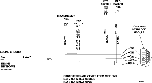
Check Engine Starting Circuit Chart
Note: In the Check Engine Starting Circuit Chart, the state of system item that is bold is being checked in each scenario.
| System | ||||||
| Neutral Lock/Parking Brake | PTO (Blades) | Ignition Key | Transmission Shift Lever | Outcome | ||
| State of System | Engaged or Disengaged | Disengaged or Engaged | Off | In Neutral or Any speed except neutral | Starter must not crank | |
 |  |  |  |  |
||
| Engaged | Disengaged | Run | Any speed except neutral | Starter must not crank | ||
| | | | |
||
| Engaged | Engaged | Run | In Neutral | Starter must not crank | ||
| | | | |
||
| Disengaged | Engaged | Run | In Neutral | Starter must not crank | ||
| | | | |
||
| Disengaged | Disengaged | Run | Any speed except neutral | Starter must not crank | ||
| | | | |
||
Check for Loose Hardware
| Maintenance Service Interval | Maintenance Procedure |
|---|---|
| Before each use or daily |
|
-
Stop engine, wait for all moving parts to stop, and remove key. Engage parking brake.
-
Visually inspect machine for any loose hardware or any other possible problem. Tighten hardware or correct the problem before operating.
Service Air Cleaner
| Maintenance Service Interval | Maintenance Procedure |
|---|---|
| Every 25 hours |
|
| Every 100 hours |
|
| Every 200 hours |
|
-
Stop engine, wait for all moving parts to stop, and remove key or spark plug wire(s). Engage parking brake.
-
See the Engine Owner's Manual for maintenance instructions.
Change Engine Oil
| Maintenance Service Interval | Maintenance Procedure |
|---|---|
| After the first 5 hours |
|
| Every 100 hours |
|
-
Stop engine, wait for all moving parts to stop, and remove key. Engage parking brake.
-
Drain oil while engine is warm from operation.
-
Remove the oil drain plug from the right hand side of the engine. Allow oil to drain, replace drain plug.
-
Replace the oil filter per the engine owner's manual. Clean around oil filter and unscrew filter to remove. Before the new filter is installed, apply a thin coating of Exmark 4–Cycle Premium Engine Oil on the surface of the rubber seal. Turn filter clockwise until rubber seal contacts the filter adapter, then tighten filter an additional 2/3 to 3/4 turn.
-
Clean around oil fill cap and remove cap. Fill to specified capacity and replace cap.
-
Use oil recommended in the Check Engine Oil Level section. Do Not overfill. Start the engine and check for leaks. Stop engine and recheck oil level.
-
Wipe up any spilled oil from engine deck mounting surfaces.
Check Tire Pressures
| Maintenance Service Interval | Maintenance Procedure |
|---|---|
| Every 40 hours |
|
-
Stop engine, wait for all moving parts to stop, and remove key. Engage parking brake.
-
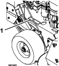
Check tire pressure in drive tires.
-
Inflate drive tires to 12–16 psi (83–110 kPa).
-
Inflate tires to pressures stated above. Measure the circumference of each drive tire. Adjust tire pressures within the above range to try to make tire circumferences match as closely as possible.
-
Semi-pneumatic caster tires Do Not need to be inflated.
Note: A more uniform cutting height may be obtained with higher tire pressure on rough terrain. A lower tire pressure provides more flotation.
Check Condition Of Belts
| Maintenance Service Interval | Maintenance Procedure |
|---|---|
| Every 40 hours |
|
-
Stop engine, wait for all moving parts to stop, and remove key. Engage parking brake.
-
Remove the mower deck belt shield to check mower blade drive belt condition.
-
Look under engine deck to check the transmission drive belt condition.
-
Inspect wheel drive belt conditions.
-
Check all idler arms to be sure they pivot freely. Disassemble, clean and grease pivot bushings if necessary.
Lubricate Grease Fittings
| Maintenance Service Interval | Maintenance Procedure |
|---|---|
| Before each use or daily |
|
| Every 40 hours |
|
Note: See chart for service intervals.
-
Stop engine, wait for all moving parts to stop, and remove key. Engage parking brake.
-
Lubricate fittings with NLGI grade #2 multi-purpose gun grease.
Refer to the following chart for fitting locations and lubrication schedule.
Lubrication Chart
Fitting Locations Initial Pumps Number of Places Service Interval 32 inch Deck 36 inch Deck 48 inch Deck 1. Front Caster Wheel Bearings 12 2 2 2 Daily 2. Front Caster Pivots 2 2 2 2 Daily 3. Drive Wheels 18 2 2 2 Daily 4. Drive Wheel Idler Arm 2 2 2 2 Daily 5. Brake Arm 2 2 2 2 40 hours 6. Trans-mission Output Shaft Coupler 2 2 2 2 40 hours 7. Mower Deck Idler Pivots 2 1 1 1 40 hours 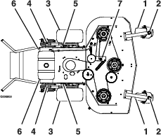
48 inch Deck Shown for Reference Only
Number 4 and 7 (Idler Arm Pivots) Disassemble and grease once a month under a “No Load” condition Number 6 (Transmission Coupler) Located below fuel tank support -
Replace 5-speed gearbox grease yearly. Use 18 oz. of Peerless grease (Part No. 788067). See Check Grease Level, Input and Output Shaft Bearing Wear on Peerless Transmission section for special lubrication instructions.
-
Lubricate pivot points with a spray penetrating lubricant as shown in the Spray Lubricant Chart.
Spray Lubricant Chart
Number of Places Pivot Points 32 inch Deck 36 inch Deck 48 inch Deck Service Interval 1. Blade Engagement Bellcrank 1 1 1 40 hours
Change Fuel Filter
A fuel filter is installed in the fuel line between the fuel tank and the engine. Replace when necessary.
Adjustments
Note: Disengage PTO, shut off engine, wait for all moving parts to stop, engage parking brake, and remove key before servicing, cleaning, or making any adjustments to the unit.
Adjusting the Cutting Height
The cutting height of the mower deck is adjusted from 1 inch to 4 1/4 inches (2.54 cm to 11.4 cm) in 1/4 inch (.64 cm) increments by adjusting the axle position, number of spacers below the caster hub, and number of spacers between blade and spindle.
Refer to the Cutting Height Adjustment table and select a cutting height range in the left hand column which corresponds to the range of cutting heights you will most often be using. Adjustments within this range can then be made by adjusting the number of blade spacers between the blade and the bottom of the spindle (this is a much easier adjustment to make than adjusting axle position and number of spacers below caster support hub).
Note that:
-
For the best cut and discharge, place a minimum of two spacers between the blade and the spindle.
-
For highest quality cut, place all four spacers between the blade and the spindle.
-
If mulching kit is installed, the highest quality cut can be obtained with 3 spacers between the blade and the spindle (minimum is 1 for a good cut).
-
When mulching leaves it is best to have fewer spacers between blade and spindle.
Refer to the table and select desired cutting height range. Refer to Adjusting the Axle Position, Adjusting the Number of Spacers below Caster Support Hub, and Adjusting the Cutting Height with Blade Spacers and sections to make adjustments make adjustment to obtain specific cutting height.
| Cutting Height Range | Axle Position (Figure 10) | Number Of Spacers Below Caster Support Hub | Number of 1/4 inch (.64 cm) Blade Spacers Below Spindle | |||||
|---|---|---|---|---|---|---|---|---|
| 1/2 inch(1.2 cm) | 3/16 inch(.48 cm) | 4 | 3 | 2 | 1 | 0 | ||
| 1–2 inches(2.5–5.0 cm) | A | 0 | 0 | 1 inch (2.5 cm) | 1 1/4 inch (3.2 cm) | 1 1/2 inch (3.5 cm) | 1 3/4 inch (4.4 cm) | 2 inch (5.0 cm) |
| 1 1/8–2 1/8 inches (2.9–5.4 cm) | A | 0 | 1 | 1 1/8 inch (2.9 cm) | 1 3/8 inch (3.5 cm) | 1 5/8 inch (4.1 cm) | 1 7/8 inch (4.8 cm) | 2 1/8 inch (5.4 cm) |
| 1 3/8– 2 3/8 inches (3.5–6.0 cm) | A | 1 | 0 | 1 3/8 inch (3.5 cm) | 1 5/8 inch (4.1 cm) | 1 7/8 inch (4.8 cm) | 2 1/8 inch (5.4 cm) | 2 3/8 inch (6.0 cm) |
| 1 3/8–2 3/8 inches (3.5–6.0 cm) | B | 0 | 1 | 1 3/8 inch (3.5 cm) | 1 5/8 inch (4.1 cm) | 1 7/8 inch (4.8 cm) | 2 1/8 inch (5.4 cm) | 2 3/8 inch (6.0 cm) |
| 1 5/8–2 5/8 inches (4.1–6.7 cm) | B | 1 | 0 | 1 5/8 inch (4.1 cm) | 1 7/8 inch (4.8 cm) | 2 1/8 inch (5.4 cm) | 2 3/8 inch (6.0 cm) | 2 5/8 inch (6.7 cm) |
| 1 3/4–2 3/4 inches (4.4–7.0 cm) | B | 1 | 1 | 1 3/4 inch (4.4 cm) | 2 inch (5.0 cm) | 2 1/4 inch (5.7 cm) | 2 1/2 inch (6.4 cm) | 2 3/4 inch (7.0 cm) |
| 2–3 inches (5.0–7.6 cm) | B | 2 | 0 | 2 inch (5.0 cm) | 2 1/4 inch (5.7 cm) | 2 1/2 inch (6.4 cm) | 2 3/4 inch (7.0 cm) | 3 inch (7.6 cm) |
| 1 7/8–2 7/8 inches (4.8–7.3 cm) | C | 1 | 1 | 1 7/8 inch (4.8 cm) | 2 1/8 inch (5.4 cm) | 2 3/8 inch (6.0 cm) | 2 5/8 inch (6.7 cm) | 2 7/8 inch (7.3 cm) |
| 2 1/8–3 1/8 inches (5.4–7.9 cm) | C | 2 | 0 | 2 1/8 inch (5.4 cm) | 2 3/8 inch (6.0 cm) | 2 5/8 inch (6.7 cm) | 2 7/8 inch (7.3 cm) | 3 1/8 inch (7.9 cm) |
| 2 1/4–3 1/4 inches (5.7–8.3 cm) | C | 2 | 1 | 2 1/4 inch (5.7 cm) | 2 1/2 inch (6.4 cm) | 2 3/4 inch (7.0 cm) | 3 inch (7.6 cm) | 3 1/4 inch (8.3 cm) |
| 2 1/2–3 1/2 inches (6.4–8.9 cm) | C | 3 | 0 | 2 1/2 inch (6.4 cm) | 2 3/4 inch (7.0 cm) | 3 inch (7.6 cm) | 3 1/4 inch (8.3 cm) | 3 1/2 inch (8.9 cm) |
| 2 3/8–3 3/8 inches (6.0–8.6 cm) | D | 2 | 1 | 2 3/8 inch (6.0 cm) | 2 5/8 inch (6.7 cm) | 2 7/8 inch (7.3 cm) | 3 1/8 inch (7.9 cm) | 3 3/8 inch (8.6 cm) |
| 2 1/2– 3 1/2 inches (6.4–8.9 cm) | D | 3 | 0 | 2 1/2 inch (6.4 cm) | 2 3/4 inch (7.0 cm) | 3 inch (7.6 cm) | 3 1/4 inch (8.3 cm) | 3 1/2 inch (8.9 cm) |
| 2 3/4–3 3/4 inches (7.0–9.5 cm) | D | 3 | 1 | 2 3/4 inch (7.0 cm) | 3 inch (7.6 cm) | 3 1/4 inch (8.3 cm) | 3 1/2 inch (8.9 cm) | 3 3/4 inch (9.5 cm) |
| 3–4 inches (7.6–10.1 cm) | D | 4 | 0 | 3 inch (7.6 cm) | 3 1/4 inch (8.3 cm) | 3 1/2 inch (8.9 cm) | 3 3/4 inch (9.5 cm) | 4 inch (10.1 cm) |
| 2 7/8–3 7/8 inches (7.3–9.8 cm) | E | 3 | 1 | 2 7/8 inch (7.3 cm) | 3 1/8 inch (7.9 cm) | 3 3/8 inch (8.6 cm) | 3 5/8 inch (9.2 cm) | 3 7/8 inch (9.8 cm) |
| 3 1/8–4 1/8 inches (7.9–10.5 cm) | E | 4 | 0 | 3 1/8 inch (7.9 cm) | 3 3/8 inch (8.6 cm) | 3 5/8 inch (9.2 cm) | 3 7/8 inch (9.8 cm) | 4 1/8 inch (10.5 cm) |
| 3 1/4–4 1/4 inches (8.3–10.8 cm) | E | 4 | 1 | 3 1/4 inch (8.3 cm) | 3 1/2 inch (8.9 cm) | 3 3/4 inch (9.5 cm) | 4 inch (10.1 cm) | 4 1/4 inch (10.8 cm) |
Important: Always adjust the Number of Spacers below Caster Hub to correspond to the Axle Position as shown in table to obtain proper “rake” (blades should always be level to the ground or tipped slightly down at the front).
Adjusting the Axle Position
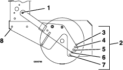
Desired cutting height range can be obtained by adjusting the rear axle and placing caster spacers above or below the caster arm (See Figure 10 and Figure 11 along with the Cutting Height Adjustment Chart). It may be necessary to readjust wheel drive and brake linkages.
To adjust rear axle:
-
Stop the machine and move the drive levers to the neutral lock position.
-
Disengage the PTO.
-
Place the drive levers in the neutral lock position.
-
Remove mower deck belt shield for access to axle adjustment bolts.
-
Loosen but do not remove the two axle pivot bolts and the two axle adjustment bolts (see Figure 10).
-
Place a jack under the rear center of the engine deck.
-
Raise the back end of the engine deck up enough to remove the two axle adjustment bolts.
-
With the jack, raise or lower the back end of the engine deck so that two axle adjustment bolts can be reinstalled in desired hole location. A tapered punch can be used to help align the holes.
-
Retighten all four bolts, lower unit and remove jack.
-
Install mower deck belt shield.
-
Adjust wheel drive and brake linkages as required (see Brake and Wheel Drive Linkage Adjustment section).
Note: The axle positions are in 1/2 inch (1.3 cm) increments and the large caster spacers are 1/2 inch (1.3 cm) thick. Therefore, by adjusting the same number of 1/2 inch (1.3 cm) caster spacers as axle hole positions the blades will retain the same front-to-back tip (rake).
Adjusting the Number of Spacers below Caster Support Hub
-
Stop the machine and move the drive levers to the neutral lock position.
-
Disengage the PTO.
-
Place the drive levers in the “park brake” position.
-
Push down on handles to lift front casters off the ground.
-
Support with jackstands.
-
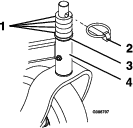
Remove “quick pin” from one caster and remove caster from hub (see Figure 11).
-
Adjust the number of 1/2 inch spacers between bottom of hub and caster yoke to obtain the desired cutting height from the Cutting Height Adjustment Table in the Adjusting the Cutting Height section.
-
Install remaining spacers on top of hub.
-
Install “quick pin”.
-
Repeat for other caster.
Adjusting the Cutting Height with Blade Spacers
-
Stop the machine and move the drive levers to the neutral locked position.
-
Disengage the PTO.
-
Engage the park brake.
-
Stop the engine, remove the key and wait for all moving parts to stop.
-
Blades may be adjusted for cutting height by using the four 1/4 inch (.64 cm) spacers found on the blade spindle bolts (factory setting is two above and two below). This allows a 1 inch (2.5 cm) range in 1/4 inch (.64 cm) increments of cutting height in any axle position. The same number of blade spacers must be used on all blades to achieve a level cut (two above and two below, one above and three below, etc.).
-
Raise front of deck and support with jack stands.
-
Hold blade bolt on bottom and loosen spindle nut on top.
-
Adjust number of spacers between bottom of spindle and blade as indicated in the Cutting Height Adjustment Table and notes in the Adjusting the Cutting Height section.
-
Install unused spacers between top of spindle and spindle nut.
-
Torque bolt to 75–80 ft-lb (102–109 N-m) (see Figure 12).
Transmission Belt Adjustment
-
Stop engine and wait for all moving parts to stop. Engage parking brake. Remove key or spark plug wire(s).
-
To tighten transmission belt, loosen the 3/8 inch nyloc nut on transmission belt idler pulley. Slide bolt inward in slot and retighten nyloc nut.
-
When properly adjusted, the belt should have 1/2 inch (1.3 cm) of deflection with three pounds of pressure on the belt midway between the transmission and engine pulley.
Wheel Drive Belt Pulley Scrapers
-
Stop engine and wait for all moving parts to stop. Engage parking brake. Remove key or spark plug wire(s).
-
Be sure mud and grass scraper, on each side, is adjusted properly and centered in the pulley grooves. The pointed part of the scraper should be centered and as deep in the pulley groove as possible without rubbing at any point.
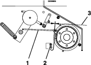
Engine to Mower Deck Belt
-
Stop engine and wait for all moving parts to stop. Engage parking brake. Remove key or spark plug wire(s).
-
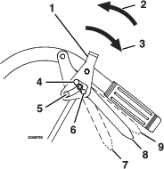
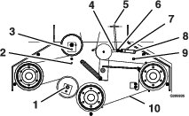
Check the adjustment of the lower blade drive linkage located between the bellcrank on the engine deck and assist arm on the mower deck. Lengthen or shorten the linkage. When properly adjusted, there should be 1/16 inch to 1/8 inch (2–3 mm) of clearance between bell-crank and transmission output shaft when belt is engaged. Make sure the assist arm is against the rear assist arm stop on the deck (see Figure 13). Push the lever down to the disengaged position. The assist arm should contact the front assist arm stop on the deck. If it does not contact, readjust so that the bellcrank is closer to the transmission output shaft.
-
Belt must be tight enough to not slip during heavy loads while cutting grass. Over-tensioning will reduce belt and spindle bearing life. To adjust belt tension, loosen the 5/16 inch whizlock nut on turnbuckle and rotate the turnbuckle; rotate turnbuckle toward rear of mower to tighten, and toward front of mower to loosen belt tension (see Figure 13). Leave a minimum of 5/16 inch (.79 cm) of the eyebolt threads engaged on both ends of the turnbuckle.
For 48” Decks: If there is no adjustment left in the turnbuckle and the belt is still loose, the rear idler pulley can be repositioned in the front hole (See Figure 12). The belt guide located next to the pulley must also be repositioned in the front hole when the pulley is moved. The turnbuckle will need to be readjusted.
Check belt tension after the first hour of operation and at least twice during the first 24 hours of operation. Adjust as necessary.
-
Proper belt tension will require about 10 lb (4.5 kg) side pull on belt, halfway between pulleys (see Figure 13, item 10–Point A) to deflect belt 1/2 inch (12 mm).
-
Check belt guide under the engine deck to see that it is properly set (see Belt Guide Adjustment section). Also check the blade brake adjustment (see Blade Brake Adjustment section).
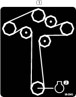
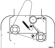
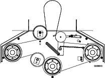
Mower Deck Belt Routings:
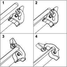
Blade Brake Adjustment
-
Stop engine and wait for all moving parts to stop. Engage parking brake. Remove key or spark plug wire(s).
-
Disengage blades.
-
Make sure the blade brake pad rests against the sheave. Adjust the spring mounting bolts to properly align the pad on the sheave (see Figure 16).
-
Check the distance between the spacer and the nut at the end of the blade brake rod. The distance should be between 1/8 inch and 3/16 inch (3–5 mm) (see Figure 16).
-
Engage the blade control and check to make sure the blade brake pad clears the sheave.
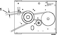
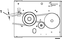
Belt Guide Adjustment
-
Stop engine and wait for all moving parts to stop. Engage parking brake. Remove key or spark plug wire(s).
-
Engage the blade drive belt.
-
Check belt guide under the engine deck for proper adjustment (See Figure 17 and Figure 18). Adjust as necessary.
The disengaged belt should not drag or fall off pulley when guides are properly adjusted.
Brake and Wheel Drive Linkage Adjustment
-
Check for correct brake adjustment:
Place the drive levers in the “park brake” position. The mower should not move forward or backward. If it does, tighten the wingnuts.
Place the drive levers in the “neutral lock” position. The mower should move forward and backward freely. If it does not, brake adjustment is necessary
-
Adjust brakes by adjusting wingnut on the upper end of each brake rod. Tighten the wingnut until the brakes engage when the drive levers are squeezed enough to allow the neutral lock/park brake latches to be placed into the “park brake” position.
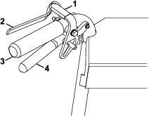
See Figure 6 for Standard Pistol Grip handles and Figure 7 for ECS handles.
Note: The neutral lock/park brake latches must be able to be moved into the park brake position, if not, the brake linkages must be adjusted again.
-
Check for correct wheel drive linkage adjustment.
-
For Pistol Grip Handles
Allow drive levers to drop into the full forward position: The clevis pin should rest in the neutral lock latch with approximately 3/16 inch to 1/4 inch (4.7–6.4 mm) clearance from the bottom of the slot (see Figure 19). Adjust if necessary.
To adjust the wheel drive linkage:
-
For wheel drive linkage adjustment, remove the hairpin between the neutral lock latch and drive lever (Figure 19).
-
Adjust drive linkage length by threading into or out of the swivel until there is a 3/16 inch to 1/4 inch (.47-.64 cm) clearance between the linkage assembly and the bottom of the slot in the neutral lock/park brake latch (see Figure 20).
Note: Neutral lock/park brake latch clearance should be checked when there is a slight upward force placed on the drive levers to remove any "slack" in the linkage.
-
Re-install hairpin into hole on the clevis pin between the neutral lock/park brake latch and drive lever (See Figure 19). Repeat procedure on opposite side of unit.
-
-
For ECS Handles:
Allow drive levers to drop into the full forward position: the flat edge of the drive lever should align with the bottom roller notch (See Figure 21). Adjust if necessary
To adjust the wheel drive linkage:
-
Locate a drive lever linkage on one side of the unit and remove the 5/16-18 x 1 3/4 inch hex cap screw and 5/16-18 inch nyloc nut (see Figure 22).
-
Thread drive lever linkage into or out of the swivel located on the wheel drive idler arm until the flat edge of the drive lever aligns with bottom of the roller notch in the neutral lock/park brake latch (see Figure 22).
-
Re-install the 5/16-18 x 1 3/4 inch hex cap screw and secure with the 5/16-18 inch nyloc nut. Repeat for the other side (see Figure 22).
-
-
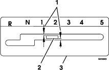
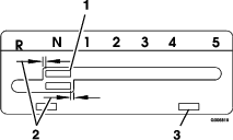
Shifter Lever Adjustment
The shifter lever in neutral should not contact the upper or lower edge of the slot or the left edge of the upper slot or the right edge of the bottom slot (See Figure 23 and Figure 24). The clearance should be equal. Adjust the shifter lever and shifter plate if necessary.
-
To adjust the shifter lever:
-
Remove the 3/8 inch nyloc nut and spring disc washer from the stud on top of the transmission (See Figure 25).
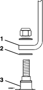
-
Remove the shifter lever and bend it slightly. Do Not bend the lever while it is attached to the transmission.
-
Re-install lever and torque the 3/8 inch nyloc nut to 35 ft-lb (47 N-m).
-
-
To adjust shifter plate:
Note: The square-hole washer must be between the lever and the transmission.
Place shifter lever in the neutral position. Loosen the two bolts securing the shifter plate to the shifter lever legs. Adjust shifter plate and retighten bolts.
Shifter Detent Adjustment
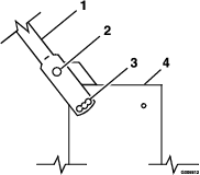
Transmission shifter detent can be adjusted by adjusting the setscrew on the back side of transmission located just behind the neutral start switch. Turn setscrew in (clockwise) to hold the transmission shifter more positively in each gear and to increase the force on the lever required to shift gears.
Turn setscrew out (counterclockwise) to decrease force on lever required to shift gears. Factory setting is to turn setscrew all the way in then back out 1 1/2 turns.
Important: Screwing setscrew in too far will prevent the transmission from shifting.
PTO Safety Switch Adjustment
-
Stop engine and wait for all moving parts to stop. Engage parking brake. Remove key or spark plug wire(s).
-
With the blades disengaged and the bellcrank touching the engine deck, adjust the blade safety switch (if needed) until the bellcrank depresses the plunger by 1/4 inch (.64 cm).
-
Be sure the bellcrank does not contact the switch body to prevent damage to the switch.
-
Retighten switch mounting hardware.
Handle Height Adjustment
The handle can be pivoted to allow positioning in one of the three holes allowing various adjustments for operator comfort (see Figure 26).
To adjust the handle height:
-
Remove the bottom mounting hardware on each side of the handle.
-
Pivot the handle to one of the three positions.
-
Re-install hardware and tighten.
Important: If the handle height position is changed, it will be necessary to readjust the drive and brake linkage (see Check Brake and Wheel Drive Linkage Adjustment section in Operation.)
Note: Adjustment Holes are actually in the side of the fuel tank support.
Wheel Drive Spring Tension Adjustment
It may be necessary to increase wheel drive belt tension under certain operating conditions such as, wet grass, hilly terrain, or while pulling a sulky.
-
Stop engine and wait for all moving parts to stop. Engage parking brake. Remove key or spark plug wire(s).
-
Disengage neutral lock/park brake latches and release drive levers to lower spring force.
-
Remove the 5/16-18 inch whizlock nut securing the adjustment bolt to the drive wheel shield. Locate bolt assembly in the desired position as follows:
-
Position A-Normal Conditions
-
Position B-More Severe
-
Position C-Most Severe
Note: Lever force is lowest with bolt assembly in Position A and will increase in Positions B and C (see Figure 27).
-
Cleaning
Clean Engine and Exhaust System Area
| Maintenance Service Interval | Maintenance Procedure |
|---|---|
| Before each use or daily |
|
Caution
Excessive debris around engine cooling air intake and exhaust system area can cause engine and exhaust system area to overheat which can create a fire hazard.
Clean all debris from engine and exhaust system area.
-
Stop engine, wait for all moving parts to stop, and remove key. Engage parking brake.
-
Clean all debris from rotating engine air intake screen, around engine shrouding, and exhaust system area.
-
Wipe up any excessive grease or oil around the engine and exhaust system area
Remove Engine Shrouds and Clean Cooling Fins
| Maintenance Service Interval | Maintenance Procedure |
|---|---|
| Every 100 hours |
|
-
Stop engine, wait for all moving parts to stop, and remove key. Engage parking brake.
-
Remove cooling shrouds from engine and clean cooling fins. Also clean dust, dirt, and oil from external surfaces of engine which can cause improper cooling.
-
Make sure cooling shrouds are properly reinstalled. Operating the engine without cooling shrouds will cause engine damage due to overheating.
Clean Debris From Machine
| Maintenance Service Interval | Maintenance Procedure |
|---|---|
| Before each use or daily |
|
-
Stop engine, wait for all moving parts to stop, and remove key. Engage parking brake.
-
Clean off any oil, debris, or grass build-up on the machine and cutting deck, especially under deck belt shields, around the fuel tank, around engine and exhaust area.
Important: You can wash the machine with mild detergent and water. Do not pressure wash the machine. Avoid excessive use of water, especially near the control panel, around the engine, hydraulic pumps, and motors.
Clean Grass Build-Up Under Deck
| Maintenance Service Interval | Maintenance Procedure |
|---|---|
| Before each use or daily |
|
-
Disengage PTO.
-
Stop engine and wait for all moving parts to stop. Engage parking brake. Remove key or spark plug wire(s).
-
Raise deck and support unit using jack stands or equivalent support.
-
Clean out any grass build-up from underside of deck and in discharge chute.
Waste Disposal
Motor Oil Disposal
Engine oil is a pollutant to the environment. Dispose of used oil at a certified recycling center or according to your state and local regulations.