Installation
Preparing the Machine
-
Park the machine on a level surface.
-
Lower the cutting units to the ground.
-
Engage the parking brake.
-
Shut off the engine and remove the key.
-
Remove the cutting unit from the machine; refer to your machine Operator’s Manual.
Removing the Existing Groomer Shaft and Driven Pulley
-
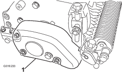
Remove the belt cover from the groomer housing (Figure 1).
-
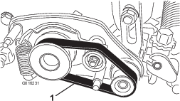
Remove the belt from the driver pulley, idler pulley, and driven pulley (Figure 2).
-
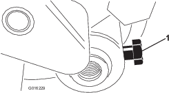
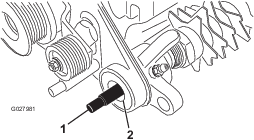
Loosen the bolt that secures the roller shaft to the height-of-cut arm (Figure 3).
-
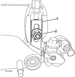
Remove the locknut and washer that secures the rod end of the height-of-cut arm assembly to the groomer-drive assembly (Figure 4).
-
Remove the plow bolt, nut, and washer that secures the height-of-cut-arm assembly to the side plate (Figure 5).
-
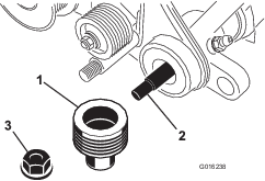
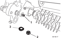
Remove the flange locknut that secures the driven pulley to the end of the groomer shaft (Figure 6). Remove the pulley.
Note: The locknut and pulley can be discarded.
-
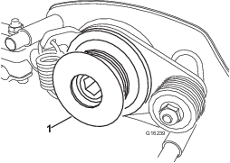
Remove the groomer drive pulley from the reel shaft (Figure 7).
-
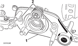
Remove the 2 shoulder bolts that secure the drive-plate assembly to the cutting-unit frame (Figure 8).
-
Remove the groomer-drive-plate assembly (Figure 8) from the grooming shaft and cutting unit, and locate and retrieve the groomer shim.
Note: The groomer shim is located between the drive-plate assembly and the cutting-unit side plate. You may need to retrieve it when you remove the drive-plate assembly.
-
Carefully pull the grooming-shaft assembly from the left support plate.
Note: The shaft assembly can be discarded.
-
Inspect the following components for wear or damage:
-
Seals, bushings, and bearings in the drive plate, support plate, and groomer arms.
-
Pulleys and idler components.
Replace these components as needed.
-
Installing the Kit
Parts needed for this procedure:
| Groomer shaft | 1 |
| Cover | 1 |
| Driven pulley | 1 |
| Spacer | 1 |
| Flange locknut | 1 |
Installing the Blades and Spacers to the Groomer Shaft
Install your desired grooming blade and spacer configuration to the groomer shaft. Contact your authorized Toro distributor to acquire additional blades or spacers.
Installing the Groomer Shaft and Driven Pulley
-
Apply a light coating of grease to the ends of the grooming shaft and to the seal lips (Figure 9) in the drive and support plates. Ensure that all bearings, bushings, and seals are properly installed.
-
Ensure that an O-ring (included in the groomer-shaft assembly) is installed on the grooming shaft and apply a light coating of grease to the O-ring.
-
Carefully place the grooming-shaft assembly into the left support plate (i.e., left side of the cutting unit).
Important: While installing the assembly, ensure that you do not damage the support-plate seal or the O-ring on the shaft.
-
Apply a light coating of grease to the O-ring on the drive-plate-assembly pivot hub and the pilot bore of the cutting-unit side plate (right side of the cutting unit).
-
Position the groomer shim [removed in step 9 in Removing the Existing Groomer Shaft and Driven Pulley] to the drive-plate assembly.
-
Carefully place the drive-plate assembly onto the groomer shaft.
Important: While installing the assembly, ensure that you do not damage the drive-plate seals.
-
Position the groomer-drive-plate assembly to the cutting-unit frame and secure it to the frame with 2 shoulder bolts (Figure 10). Ensure that the drive plate rotates freely after installation.
-
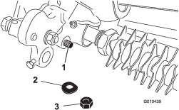
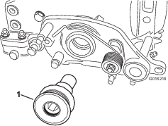
Apply a light coating of grease to the driven-pulley (Figure 11) hub.
Important: Ensure that grease is not on the pulley surface that contacts the belt.
-
Slide the driven pulley onto the grooming shaft (Figure 11).
Important: Install the pulley carefully so that you do not damage the side-plate seal.
-
Secure the pulley to shaft with a flange locknut (Figure 11) and torque it to 23 to 28 N∙m (17 to 21 ft-lb).
Note: To prevent the grooming-reel shaft from turning when you install the driven pulley, use a wrench on the shaft flats to hold the shaft steady.
Installing the Groomer Drive Pulley
-
Use a piece of wood to prevent the reel from movement while you install the pulley.
Warning
Contact with the reel can result in personal injury.
Keep your fingers and clothing away from the reel.
-
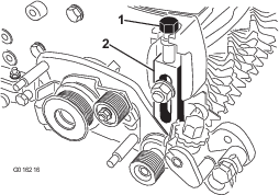
Secure the groomer drive pulley to the reel shaft (Figure 12).
-
Torque the groomer drive pulley (Figure 12) to 170 N∙m (125 ft-lb).
Important: Using an impact gun to torque the pulley is not enough to ensure proper installation. Failure to properly torque the drive pulley can result in the assembly unscrewing itself during operation.
Installing the Height-of-Cut Arms and Roller
-
Thread the height-of-cut adjusting screw into the top of the right-adjuster-arm assembly (Figure 13).
-
Install the right-hand adjuster-arm assembly to the cutting-unit side plate using the existing plow bolt, nut, and new washer. Ensure that the rod end of the height-of-cut arm assembly slides into the bushing in the hole in the groomer drive assembly (Figure 13).
-
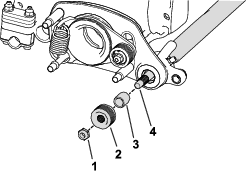
Secure the adjuster-arm assembly-rod end to the groomer drive assembly with the previously-removed washer and locknut (Figure 14).
Note: Do not overtighten the locknut. The washer should be compressed but the arm must be free to pivot.
-
Insert the roller shaft into the right adjuster arm and loosely secure it with the roller-shaft bolt (Figure 15).
-
Thread the height-of-cut adjusting screw into the top of the left-hand, adjuster-arm assembly (Figure 13).
-
Insert the roller shaft into the left adjuster arm. Do not tighten the bolt at this time.
-
Install the left-hand adjuster-arm assembly to the cutting-unit side plate using the existing plow bolt, nut, and new washer (Figure 13).
Note: Ensure that the rod end slides into the bushing in the hole in the groomer drive assembly.
-
Secure the adjuster-arm assembly-rod end to the groomer drive assembly with a washer and locknut (Figure 14).
Completing the Installation
-
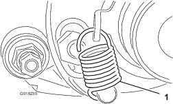
Rotate the idler pulley until the shift-lever spring can be hooked into the hole in the pulley bracket and onto the stud as shown in Figure 16.
-
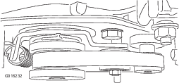
Insert the belt onto the driver pulley, idler pulley, and driven pulley as shown in Figure 17.
Important: Ensure that the belt is centered on the pulleys and in the grooves as shown in Figure 18.
-
Mount the new belt cover to the groomer housing assembly with 3 locknuts (Figure 19).
-
Center the roller between the adjuster arms and tighten the mounting bolts (Figure 15).