Introduction

This machine seeds, dethatches, and power rakes turf both for revitalizing existing turf and for spreading seed. It is intended for small to medium sized lawn applications in residential and commercial properties. Using this product for purposes other than its intended use could prove dangerous to you and bystanders.

Read this information carefully to learn how to operate and maintain your product properly and to avoid injury and product damage. You are responsible for operating the product properly and safely.

Visit www.Toro.com for product and accessory information, help finding a dealer, or to register your product.

Whenever you need service, genuine Toro parts, or additional information, contact an Authorized Service Dealer or Toro Customer Service and have the model and serial numbers of your product ready. Figure 1 identifies the location of the model and serial numbers on the product. Write the numbers in the space provided.

Important: With your mobile device, you can scan the QR code (if equipped) on the serial number decal or go to www.Toro.com to access warranty, parts, and other product information.

g252246

This manual identifies potential hazards and has safety messages identified by the safety-alert symbol (Figure 2), which signals a hazard that may cause serious injury or death if you do not follow the recommended precautions.

g000502

This manual uses 2 words to highlight information. Important calls attention to special mechanical information and Note emphasizes general information worthy of special attention.

This product complies with all relevant European directives; for details, please see the separate product specific Declaration of Conformity (DOC) sheet.

It is a violation of California Public Resource Code Section 4442 to use or operate the engine on any forest-covered, brush-covered, or grass-covered land without a spark arrester muffler maintained in working order, or the engine constricted, equipped, and maintained for the prevention of fire. Other states or federal areas may have similar laws.

Because in some areas there are local, state, or federal regulations requiring that a spark arrester be used on the engine of this machine, a spark arrester is available as an option. If you require a spark arrester, contact your Authorized Service Dealer. Genuine Toro spark arresters are approved by the USDA Forestry Service.

The enclosed engine owner's manual is supplied for information regarding the US Environmental Protection Agency (EPA) and the California Emission Control Regulation of emission systems, maintenance, and warranty. Replacements may be ordered through the engine manufacturer.

Warning

CALIFORNIA

Proposition 65 Warning

The engine exhaust from this product contains chemicals known to the State of California to cause cancer, birth defects, or other reproductive harm.

Use of this product may cause exposure to chemicals known to the State of California to cause cancer, birth defects, or other reproductive harm.

Safety

This machine has been designed in accordance with ANSI B71.4-2017 and EN ISO 5395-2. Improper use or maintenance by the operator or owner can result in injury. To reduce the potential for injury, comply with these safety instructions and always pay attention to the safety-alert symbol (Figure 2), which means Caution, Warning, or Danger—personal safety instruction. Failure to comply with the instruction may result in personal injury or death.

General Safety

This product is capable of injuring hands and feet and of throwing objects. Always follow all safety instructions to avoid serious personal injury.

  • Read and understand the contents of this Operator’s Manual before starting the engine.

  • Do not put your hands or feet near moving components of the machine.

  • Do not operate the machine without all guards and other safety protective devices in place and working on the machine.

  • Keep children and bystanders out of the operating area. Never allow children to operate the machine.

  • Stop the machine and shut off the engine before servicing, fueling, or unclogging the machine.

Improperly using or maintaining this machine can result in injury. To reduce the potential for injury, comply with these safety instructions and always pay attention to the safety-alert symbol (Figure 2), which means Caution, Warning, or Danger—personal safety instruction. Failure to comply with these instructions may result in personal injury or death.

Safety and Instructional Decals

Graphic

Safety decals and instructions are easily visible to the operator and are located near any area of potential danger. Replace any decal that is damaged or missing.

decal93-7321
decal115-9625
decal116-8535
decal116-8536
decal117-4979
decal121-6203
decal126-0296
decal126-2446
decal133-8062
decal116-8537
decal116-8648
decal121-2011

Setup

Unfolding the Handle

  1. Raise the handle to the operating position (Figure 3).

    g029059
  2. Slide the oval locking rings down each side of the upper handle and over the lower handle (Figure 3), locking the handle sections together.

Checking the Engine-Oil Level

Installing the CE Conversion Kit

Parts needed for this procedure:

CE conversion kit (optional kit—sold separately)1

For machines requiring CE compliance, install the optional CE conversion kit; refer to the CE conversion kit installation instructions.

Product Overview

g252290
g252291

Choke Lever

Before starting a cold engine, move the choke lever (Figure 5) to the left. After the engine starts, regulate the choke to keep the engine running smoothly. As soon as possible, move the choke lever all the way to the right.

Note: A warm engine requires little or no choking.

Throttle Lever

The throttle lever (Figure 5) is located on the engine and controls the engine speed. Moving the throttle lever rearward increases the engine speed, and moving the throttle lever forward decreases the engine speed.

Engine On/Off Switch

The engine on/off switch (Figure 5) is located on the front right-hand side of the engine. Rotate the switch clockwise to the ON position before starting the engine. Rotate the switch counterclockwise to the OFF position to shut off the engine.

Fuel-Shutoff Valve

The fuel-shutoff valve (Figure 5) is located on the engine and is used to shut off the fuel when the machine will not be used for a few days, during transport to and from the jobsite, and when parked inside a building.

Rotate it down to open it or up to close it.

Self-Propel Drive Bail

The self-propel drive bail (Figure 6), located under the handle, controls the forward and reverse motion of the machine.

When you squeeze the self-propel drive bail is against the handle, the ground speed of the machine changes based on the distance between the bail and the handle. When you release the bail, the machine stops moving.

g020976

Blade-Control Bail

The blade-control bail (Figure 6), located at front of the handle, and engages or disengages the blade.

If the engine is running, the blades engage when you squeeze the blade-control bail toward the handle.

When you release the blade-control bail, the blades stop.

Blade-Control Lock

The blade-control lock (Figure 6) is located on the left side of the handle, next to the blade-control bail.

Moving the blade-control lock into the full forward position allows the blade-control bail to be squeezed against the handle.

Squeezing the blade-control bail against the handle engages the blade. Releasing the blade-control bail automatically disengages the blade. The blade-control lock resets to lock the blade-control bail.

Seeder-Control Lever

The seeder-control lever (Figure 6) is located on the right handlebar.

Push the lever forward to start the seed flow, and pull it rearward to stop the seed flow.

Parking Brake

Set the parking brake whenever you leave the machine unattended and when performing maintenance. To engage the parking brake, pull the brake rod out and down, locking it in the out position. To disengage the brake, pull the brake up until it snaps back into the machine.

g017939

Hydrostatic-Drive Bypass Lever

The hydrostatic-drive bypass lever (Figure 8) releases the hydrostatic-drive system so that you can move the machine by hand without the engine running.

For normal operating position, pull up on the handle and then push it in until all 3 notches are inside the frame.

Note: The last notch on the handle does not latch on the slot.

To release the drive wheels, pull up on the handle and pull it out until the last notch engages in the slot. Then push the handle down.

g021333

Note: Specifications and design are subject to change without notice.

Width76 cm (30 inches)
Length (operating)137 cm (54 inches)
Length (with handle stored)95.25 cm (37.5 inches)
Height (operating)113 cm (44.5 inches)
Height (with handle stored)73.5 cm (29 inches)
Weight120.2 kg (265 lb)

Torque Requirements

Bolt LocationTorque
Engine mounting bolts37 to 45 N⋅m (27 to 33 ft-lb)
Clutch mounting bolts66 to 83 N⋅m (49 to 61 ft-lb)
Slicer shaft nut88 to 115 N⋅m (65 to 85 ft-lb)

Attachments/Accessories

A selection of Toro approved attachments and accessories is available for use with the machine to enhance and expand its capabilities. Contact your Authorized Service Dealer or authorized Toro distributor or go to www.Toro.com for a list of all approved attachments and accessories.

To ensure optimum performance and continued safety certification of the machine, use only genuine Toro replacement parts and accessories. Replacement parts and accessories made by other manufacturers could be dangerous, and such use could void the product warranty.

Operation

Before Operation

Note: Determine the left and right sides of the machine from the normal operating position.

Before Operation Safety

General Safety

  • Never allow children or untrained people to operate or service the machine. Local regulations may restrict the age of the operator. The owner is responsible for training all operators and mechanics.

  • Become familiar with the safe operation of the equipment, operator controls, and safety signs.

  • Know how to stop the machine and shut off the engine quickly.

  • Check that operator-presence controls, safety switches, and shields are attached and functioning properly. Do not operate the machine unless they are functioning properly.

  • Inspect the area where you will use the machine and remove all objects that the machine could contact.

  • Evaluate the terrain to determine the appropriate equipment and any attachments or accessories required to operate the machine properly and safely.

Fuel Safety

  • Use extreme care in handling fuel. It is flammable and its vapors are explosive

  • Extinguish all cigarettes, cigars, pipes, and other sources of ignition.

  • Do not remove the fuel cap or fill the fuel tank while the engine is running or hot.

  • Do not add or drain the fuel in an enclosed space.

  • Do not store the machine or fuel container where there is an open flame, spark, or pilot light, such as on a water heater or other appliance.

  • If you spill fuel, do not attempt to start the engine; avoid creating any source of ignition until the fuel vapors have dissipated.

Adding Fuel

Capacity: 5.6 L (1.48 US gallons)

Recommended Fuel

  • For best results, use only clean, fresh (less than 30 days old), unleaded gasoline with an octane rating of 87 or higher ((R+M)/2 rating method).

  • Ethanol: Gasoline with up to 10% ethanol (gasohol) or 15% MTBE (methyl tertiary butyl ether) by volume is acceptable. Ethanol and MTBE are not the same. Gasoline with 15% ethanol (E15) by volume is not approved for use. Never use gasoline that contains more than 10% ethanol by volume, such as E15 (contains 15% ethanol), E20 (contains 20% ethanol), or E85 (contains up to 85% ethanol). Using unapproved gasoline may cause performance problems and/or engine damage which may not be covered under warranty.

  • Do not use gasoline containing methanol.

  • Do not store fuel either in the fuel tank or in fuel containers over the winter unless you use a fuel stabilizer.

  • Do not add oil to gasoline.

Important: To reduce starting problems, add fuel stabilizer to the fuel all season, mixing it with gasoline less than 30 days old; run the machine dry before storing it for more than 30 days.Do not use fuel additives other than a fuel stabilizer/conditioner. Do not use fuel stabilizers with an alcohol base such as ethanol, methanol, or isopropanol.

In certain conditions, gasoline is extremely flammable and highly explosive. A fire or explosion from gasoline can burn you and others and can damage property.

  • Fill the fuel tank outdoors, in an open area, when the engine is cold. Wipe up any gasoline that spills.

  • Never fill the fuel tank inside an enclosed trailer.

  • Do not fill the fuel tank completely full. Add gasoline to the fuel tank until the level is 6 to 13 mm (1/4 to 1/2 inch) below the bottom of the filler neck. This empty space in the tank allows gasoline to expand.

  • Never smoke when handling gasoline, and stay away from an open flame or where a spark from gasoline fumes may ignite.

  • Store gasoline in an approved container and keep it out of the reach of children. Never buy more than a 30-day supply of gasoline.

  • Do not operate without the entire exhaust system in place and in proper working condition.

In certain conditions during fueling, static electricity can be released, causing a spark which can ignite the gasoline vapors. A fire or explosion from gasoline can burn you and others and can damage property.

  • Always place gasoline containers on the ground away from your vehicle before filling.

  • Do not fill gasoline containers inside a vehicle or on a truck or trailer bed, because interior carpets or plastic truck-bed liners may insulate the container and slow the loss of any static charge.

  • When practical, remove fuel-powered equipment from the truck or trailer, and fuel the equipment with the wheels on the ground. If this is not possible, then refuel such equipment on a truck or trailer from a portable container rather than from a gasoline dispenser nozzle.

  • If you must use a fuel-dispenser nozzle, keep the nozzle in contact with the rim of the fuel tank or container opening at all times until fueling is complete.

Fuel is harmful or fatal if swallowed. Long-term exposure to vapors can cause serious injury and illness.

  • Avoid prolonged breathing of vapors.

  • Keep your face away from the nozzle and the fuel tank or conditioner opening.

  • Keep fuel away from your eyes and skin.

Filling the Fuel Tank

  1. Disengage the cutting blades, shut off the engine, wait for all moving parts to stop, and turn the engine switch to the OFF position.

  2. Allow the engine to cool.

  3. Clean around the fuel-tank cap and remove it.

    Note: The cap is tethered to the fuel tank.

  4. Add unleaded gasoline to the fuel tank until the level is just inside the mesh filter basket.

    Important: This space in the tank allows gasoline to expand. Do not fill the fuel tank completely full.

  5. Install the fuel-tank cap securely.

  6. Wipe up any spilled fuel.

Checking the Engine Oil

Check the engine oil before starting the engine; refer to Checking the Engine-Oil Level.

Adjusting the Cutting-Blade Depth

  1. Bring the machine to a full stop.

  2. Disengage the cutting blades.

  3. Shut off the engine and wait for all moving parts to stop before leaving the operating position. Disconnect the wire from the spark plug.

  4. Unlock the cutting-blade depth handle by pulling upward.

    g020903
  5. Move the lever to the desired working depth slot setting. Rotate and push the handle down to lock the handle.

  6. Adjust the setting down as the cutting blades wear.

Adjusting the Seeding-Rate Gauge

  1. Bring the machine to a full stop.

  2. Disengage the cutting blades.

  3. Shut off the engine and wait for all moving parts to stop before leaving the operating position.

  4. To change the seeding rate, loosen the knob on the seeding-rate gauge located on the front of the seed hopper. Move the gauge pointer to the desired position, and tighten the knob.

    g013146

Note: Refer to the seeding graph, located on the machine, to determine the correct gauge setting for the type of grass and the thickness to be planted.

Using the Seed Cover

  • To install the seed cover (Figure 11), place it over the seed hopper and fasten it to the latch posts on either side using the rubber latches.

  • To remove the seed cover, pull each rubber latch down and away from the latch posts and remove the cover.

g024773

During Operation

During Operation Safety

General Safety

  • The owner/user can prevent and is responsible for accidents or injuries occurring to people, or damage to property.

  • Wear appropriate clothing, including eye protection; long pants; slip-resistant, substantial footwear; and hearing protection. Tie back long hair and do not wear loose jewelry.

  • Use your full attention while operating the machine. Do not engage in any activity that causes distractions; otherwise, injury or property damage may occur.

  • Do not operate the machine while ill, tired, or under the influence of alcohol or drugs.

  • Never carry passengers on the machine and keep bystanders and pets away from the machine during operation.

  • Operate the machine only in good visibility to avoid holes or hidden hazards.

  • Avoid operating the machine on wet grass. Reduced traction could cause the machine to slide.

  • Ensure that all drives are in neutral, the parking brake is engaged, and you are in the operating position before you start the engine.

  • Keep your hands and feet away from the blade area.

  • Look behind and down before backing up to be sure of a clear path.

  • Use care when approaching blind corners, shrubs, trees, or other objects that may obscure your vision.

  • Stop the blades whenever you are not operating the machine.

  • Stop the machine, shut off the engine, engage the parking brake, and inspect the blades after striking an object or if there is an abnormal vibration in the machine. Make all necessary repairs before resuming operation.

  • Slow down and use caution when making turns and crossing roads and sidewalks with the machine. Always yield the right-of-way.

  • Shut off the engine, and disengage the cutting blades before adjusting the cutting-blade depth.

  • Never run an engine in an area where exhaust gases are enclosed.

  • Never leave a running machine unattended.

  • Before leaving the operating position for any reason, do the following:

    • Stop the machine on level ground.

    • Shut off the engine.

    • Engage the parking brake.

    • Wait for all moving parts to stop.

    • Raise the blades.

  • Do not operate the machine when there is the risk of lightning.

  • Do not change the governor speed or overspeed the engine.

  • Use only accessories and attachments approved by Toro.

Slope Safety

  • Slopes are a major factor related to loss of control and rollover accidents, which can result in severe injury or death. You are responsible for safe slope operation. Operating the machine on any slope requires extra caution.

  • Evaluate the site conditions to determine if the slope is safe for machine operation, including surveying the site. Always use common sense and good judgment when performing this survey.

  • Review the slope instructions listed below for operating the machine on slopes and to determine whether you can operate the machine in the conditions on that day and at that site. Changes in the terrain can result in a change in slope operation for the machine.

  • Avoid starting, stopping, or turning the machine on slopes. Avoid making sudden changes in speed or direction. Make turns slowly and gradually.

  • Do not operate a machine under any conditions where traction, steering, or stability is in question.

  • Remove or mark obstructions such as ditches, holes, ruts, bumps, rocks, or other hidden hazards. Tall grass can hide obstructions. Uneven terrain could overturn the machine.

  • Be aware that operating the machine on wet grass, across slopes, or downhill may cause the machine to lose traction. Loss of traction to the drive wheels may result in sliding and a loss of braking and steering.

  • Use extreme caution when operating the machine near drop-offs, ditches, embankments, water hazards, or other hazards. The machine could suddenly roll over if a wheel goes over the edge or the edge caves in. Establish a safety area between the machine and any hazard.

  • Identify hazards at the base of the slope. If there are hazards, mow the slope with a pedestrian-controlled machine.

  • If possible, keep the cutting unit(s) lowered to the ground while operating on slopes. Raising the cutting unit(s) while operating on slopes can cause the machine to become unstable.

  • Use extreme caution with grass-collection systems or other attachments. These can change the stability of the machine and cause a loss of control. Always keep the machine in gear when going down slopes. Do not coast downhill (applicable only to gear-drive units).

Starting the Machine

  1. Ensure that the blade-control bail is in the OFF position.

  2. Move the engine switch to the ON position, and open the fuel-shutoff valve.

  3. Move the choke lever to the left if you are starting a cold engine.

    Note: A warm or hot engine may not require choking.

  4. Move the throttle lever midway between the SLOW (turtle) and FAST (rabbit) positions.

  5. Pull the recoil-start handle sharply to start the engine.

  6. After the engine starts, gradually move the choke to the right.

    Note: If the engine stalls or hesitates, move the choke left again until the engine warms up.

  7. Move the throttle lever to the desired setting.

Shutting Off the Machine

  1. Bring the machine to a full stop.

  2. Release the blade-control bail. The blades stop, and the engine continues to run.

  3. Place the throttle midway between the SLOW and FAST positions.

  4. Allow the engine to run for a minimum of 15 seconds, then turn the engine on/off switch to the OFF position to shut off the engine.

    Important: In an emergency, shut off the engine immediately.

  5. Close the fuel-shutoff valve.

  6. Wait for all moving parts to stop before leaving the operator’s position.

Operating the Self-Propel Drive

  1. Start the engine.

  2. Move the self-propel drive bail from the NEUTRAL position.

    • To move forward, squeeze the self-propel drive bail against the handle (Figure 12).

      g020893

      Note: You can vary the ground speed by increasing or decreasing the distance between the self-propel drive bail and the handle. Lower the drive bail toward the neutral position to decrease the ground speed when making a turn or if the machine is moving too fast. If you release the drive bail, it returns to neutral and the machine stops moving. Squeeze the drive bail closer to the handle to increase the ground speed. When you hold the drive bail tight against the handle, the machine moves at the maximum ground speed. Release the drive bail to stop moving or whenever you leave the machine.

    • To turn left or right, decrease the speed, push down on the handles, and turn the machine in the desired direction; then resume normal operation.

    • To move in reverse, release the drive bail and allow it to return to neutral. Push the drive bail down and away from the handle. The ground speed varies as the distance increases or decreases from the neutral position.

  3. To disengage the self-propel drive and place the machine into the neutral position, release the drive bail.

    Note: If the machine creeps forward or rearward when the drive bail is in the neutral position, shut off the engine and adjust the self-propel drive cable; refer to Adjusting the Self-Propel Drive.

Operating the Blade-Control Bail

  1. Start the engine.

  2. Push and hold the blade-control lock forward to release the blade-control bail (Figure 13).

    g021243
  3. Squeeze the blade-control bail against the handle and release the blade-control lock; the blades engage.

  4. Release the blade-control bail to disengage the blades. The blade-control lock resets to lock the blade-control bail.

Operating the Machine

Danger

The rotating blades under the machine are dangerous. Blade contact can cause serious injury or death.

Do not put hands or feet under the machine.

Danger

When the machine is in operation, contact with rotating or moving parts will severely injure hands and feet.

  • Before adjusting, cleaning, inspecting, troubleshooting, or repairing the machine, shut off the engine and wait for all moving parts to stop. Disconnect the wire from the spark plug and keep it away from the plug to prevent someone from accidentally starting the engine.

  • Stay behind the handle and away from the seed mixer and cutting blades while operating the machine.

  • Keep face, hands, feet, and any other part of your body or clothing away from concealed, moving, or rotating parts.

  1. If seeding, fill the seed hopper and set the seeding rate gauge; refer to Adjusting the Seeding-Rate Gauge.

  2. Adjust the cutting-blade depth to the desired setting; refer to Adjusting the Cutting-Blade Depth.

  3. Start the engine.

  4. Set the engine throttle to the FAST position.

  5. Push down on the handle to raise the front wheels slightly off the ground.

  6. Squeeze the blade-control bail against the handle to engage the blades. Slowly lower the front wheels to the ground, allowing the blades to gradually work into the grass and soil.

  7. If seeding, push the seeder-control lever forward to start the seed flow.

    Note: There is no need to turn the seeder-control lever off and on for each turn. The seed flow slows and/or stops when the machine is stopped or slowed for turning. To reduce seed loss, raise the front wheels as the machine is turned.

    Note: The machine seeds at the same rate going forward or rearward.

    Note: If there is excessive thatch, it may be necessary to remove the thatch prior to seeding.

  8. Engage the self-propel drive bail to begin operating.

Operating Tips

Overseeding

  • Set the cutting blades to be 3 to 6 mm (1/8 to 1/4 inch) into the earth.

  • As seed flow varies greatly between different seed types, fill the hopper with a minimal amount of seed and run a trial portion of the yard to ensure that you have the desired seed output.

  • For optimal coverage, reduce the seed flow to 1/2 the desired amount and seed the entire yard in one direction, then complete a second coverage perpendicular to the first.

Important: Do not put down more seed than recommended by the seed company. Overseeding can cause the grass to be too thick and cause it to be susceptible to fungus.

Dethatching

Set the cutting blades to be 3 to 6 mm (1/8 to 1/4 inch) past the thatch layer, into the earth. Operate the machine over the yard with the seeder-control lever turned off.

Power Raking/Renovating

To break new ground or till an existing lawn, set the cutting blades to be 6 to 13 mm (1/4 to 1/2 inch) into the earth. Go forward and backward over the area to be leveled, or make multiple passes from different directions.

The machine works best when the ground is hard and dry and is most aggressive in breaking up the soil in reverse. If the ground is soft and causes the engine to bog down, raise the blades slightly and make a few passes before lowering them to the full depth.

After Operation

After Operation Safety

General Safety

  • Clean grass and debris from the machine to help prevent fires. Clean up oil or fuel spills.

  • Turn off the fuel-shutoff valve before storing or transporting the machine.

  • Allow the engine to cool before storing the machine in any enclosure.

  • Never store the machine or fuel container where there is an open flame, spark, or pilot light, such as on a water heater or on other appliances.

  • Use extreme care when loading or unloading the machine into a trailer or truck.

Transporting the Machine

Warning

Loading the machine onto a trailer without strong enough or properly supported ramps could be dangerous. The ramps could collapse, causing the machine to fall, which could cause injury.

  • Use proper ramps that are secured to the truck or trailer.

  • Keep feet and legs out from under the machine when loading and unloading.

  • If necessary, use assistance when loading.

Be sure that the fuel shutoff valve is closed.

Securely fasten the machine to the trailer with straps, chains, cables, or ropes.

Be sure that the trailer has all necessary lighting and marking as required by law, and use safety chains.

Disengaging the Hydrostatic Drive

If you need to push the machine unpowered, you must release the hydrostatic drive. To release the drive, pull the hydrostatic-drive bypass lever (Figure 14) out and down, locking it in the out position. The front wheels now rotate freely.

To engage the drive, pull up on the bypass lever until it snaps back into the machine.

g017940

Maintenance

Maintenance Safety

  • Before adjusting, cleaning, or repairing the machine do the following:

    • Park the machine on a level surface.

    • Disengage the drives.

    • Shut off the engine.

    • Wait for all moving parts to stop.

    • Engage the parking brake.

    • Raise the blades.

    • Disconnect the spark-plug wire.

  • Clean grass and debris from the blades, drives, muffler, and engine to help prevent fires. Clean up oil or fuel spillage.

  • Clean up oil or fuel spills.

  • Do not allow untrained personnel to service the machine.

  • Use jack stands to support the machine and/or components when required.

  • Carefully release pressure from components with stored energy.

  • Remove the spark-plug wire before making any repairs.

  • Use care when checking the blades. Wrap the blade(s) or wear thickly padded gloves, and use caution when servicing them. Only replace blades; do not straighten or weld them.

  • Keep your hands and feet away from moving parts. If possible, do not make adjustments with the engine running.

  • Keep all parts in good working condition and all hardware tightened. Replace all worn or damaged decals.

  • Never interfere with the intended function of a safety device or reduce the protection provided by a safety device. Check their proper operation regularly.

  • To ensure optimum performance and continued safety certification of the machine, use only genuine Toro replacement parts and accessories. Replacement parts and accessories made by other manufacturers could be dangerous, and such use could void the product warranty.

  • Check the parking brake operation frequently. Adjust and service as required.

Recommended Maintenance Schedule(s)

Maintenance Service IntervalMaintenance Procedure
After the first 5 hours
  • Change the engine oil.
  • Before each use or daily
  • Inspect the air-cleaner elements.
  • Check the engine-oil level.
  • Check the tire pressure.
  • Check the blades for wear or damage.
  • Check the seed gate.
  • Clean the engine and exhaust area.(Clean the engine and exhaust area more often in dry or dirty conditions.)
  • Clean the debris buildup from under the machine.
  • Check for loose fasteners.
  • Every 25 hours
  • Grease the slicer-shaft bearings.
  • Check the condition of the belts.
  • Every 50 hours
  • Clean the air-cleaner elements.Clean them more frequently in dusty operating conditions.
  • Change the engine oil.
  • Check the spark arrester (if equipped).
  • Clean under the belt cover.
  • Every 100 hours
  • Inspect and adjust the spark plug; replace it if necessary.
  • Change the hydraulic-transmission fluid.
  • Every 200 hours
  • Replace the paper air-cleaner element.Replace it more frequently in dusty operating conditions.
  • Replace the spark plug.
  • Yearly or before storage
  • Touch up chipped paint.
  • Pre-Maintenance Procedures

    Disconnecting the Spark-Plug Wire

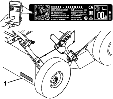
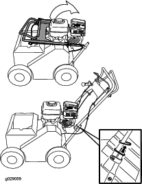
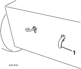
    Before performing any maintenance on the engine, belt, or cutting blades, disconnect the spark-plug wire from the spark plug (Figure 15).

    g252737

    Lubrication

    Lubricating the Slicer-Shaft Bearings

    Maintenance Service IntervalMaintenance Procedure
    Every 25 hours
  • Grease the slicer-shaft bearings.
    1. Shut off the engine, wait for all moving parts to stop, and remove the spark-plug wire.

    2. Engage the parking brake.

    3. Lubricate the fittings (Figure 16) with 1 or 2 pumps of NLGI grade No. 2 multi-purpose grease.

      g021348

    Engine Maintenance

    Engine Safety

    • Shut off the engine before checking the oil or adding oil to the crankcase.

    • Keep your hands, feet, face, clothing, and other body parts away the muffler and other hot surfaces.

    Servicing the Air Cleaner

    Maintenance Service IntervalMaintenance Procedure
    Before each use or daily
  • Inspect the air-cleaner elements.
  • Every 50 hours
  • Clean the air-cleaner elements.Clean them more frequently in dusty operating conditions.
  • Every 200 hours
  • Replace the paper air-cleaner element.Replace it more frequently in dusty operating conditions.
  • Important: Do not operate the engine without the air filter assembly; extreme engine damage will occur.

    1. Shut off the engine and wait for all moving parts to stop; refer to Maintenance Safety.

    2. Disconnect the wire from the spark plug; refer to Disconnecting the Spark-Plug Wire.

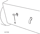
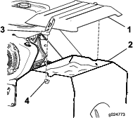
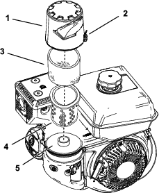
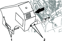
    3. Unhook the latch that secures the air-cleaner cover ().

      g232363
    4. Remove the air-cleaner cover.

      Note: Be careful to prevent dirt and debris from falling into the base.

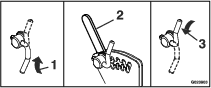
    5. Remove the foam and paper elements from the base ().

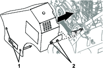
    6. Remove the foam element from the paper element ().

    7. Inspect the foam and paper elements, and replace them if they are damaged or excessively dirty.

    8. Clean the paper element by tapping it gently to remove the dirt.

      Note: Never try to brush dirt off the paper element; brushing forces the dirt into the fibers. Replace the element if tapping it fails to remove the dirt.

    9. Clean the foam element in warm, soapy water or in a nonflammable solvent.

      Note: Do not use gasoline to clean the foam element because it could create a risk of fire or explosion.

    10. Rinse and dry the foam element thoroughly.

    11. Wipe dirt from the base and the cover with a moist rag.

      Note: Be careful to prevent dirt and debris from entering the air duct leading to the carburetor.

    12. Install the air-cleaner elements and ensure that they are properly positioned.

    13. Install the cover and hook the latch to secure it.

    Servicing the Engine Oil

    Maintenance Service IntervalMaintenance Procedure
    After the first 5 hours
  • Change the engine oil.
  • Every 50 hours
  • Change the engine oil.
  • Toro Premium Engine Oil is available from your authorized Toro dealer.

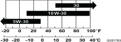
    Important: Use 4-cycle detergent engine oil that meets or exceeds the requirements for API service category SJ or higher.

    Crankcase Capacity: 1.1 L (44.7 fl oz)

    Important: If the oil level in the crankcase is too low or too high and you run the engine, you may damage the engine. This type of damage is not covered by the warranty.

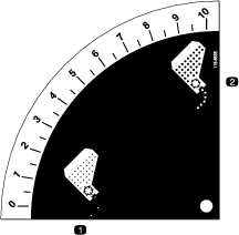
    Note: Use SAE 10W-30 for general use. You can use the other viscosities shown in the chart when the average temperature in your area is within the indicated range (Figure 18).

    g021783

    Checking the Engine-Oil Level

    Maintenance Service IntervalMaintenance Procedure
    Before each use or daily
  • Check the engine-oil level.
    1. Stop the machine on a level surface, and ensure that the engine is level.

    2. Disengage the cutting blades, shut off the engine, wait for all moving parts to stop, and turn the engine switch to the OFF position.

    3. Allow the engine to cool.

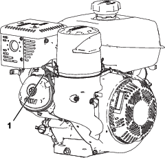
    4. Clean around the dipstick (Figure 19) so that dirt cannot fall into the fill hole and damage the engine.

      g021851
    5. Remove the dipstick, and wipe the end clean.

    6. Insert the dipstick fully into the fill hole, but do not screw it in (Figure 19).

    7. Remove the dipstick again and look at the end. If the engine-oil level is low, slowly pour only enough oil into the fill hole to raise the level to the Full mark on the dipstick (Figure 19).

    Changing the Engine Oil

    Warning

    Oil may be hot after the engine has been run, and contact with hot oil can cause severe personal injury.

    Avoid contacting the hot engine oil when you drain it.

    1. Disengage the cutting blades, shut off the engine, turn off the engine switch, and wait for all moving parts to stop.

    2. Disconnect the wire from the spark plug.

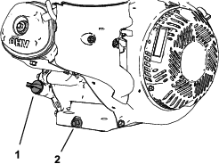
    3. Raise the front wheels 5 to 8 centimeters (2 to 3 inches) off the ground, and place a pan under the drain plug to catch the oil.

    4. Remove the drain plug (Figure 20).

      g252748
    5. When the oil has drained completely, lower the front wheels to the ground, replace the drain plug, and torque the plug to 18 N⋅m (13 ft-lb).

      Note: Dispose of the used oil at a certified recycling center.

    6. Remove the dipstick, and slowly pour oil into the fill hole until the oil pours out of the fill hole.

    7. Ensure that the oil is at the correct level on the dipstick; refer to Checking the Engine-Oil Level.

    8. Replace and secure the dipstick.

    9. Wipe up any spilled oil.

    10. Connect the wire to the spark plug.

    Servicing the Spark Plug

    Maintenance Service IntervalMaintenance Procedure
    Every 100 hours
  • Inspect and adjust the spark plug; replace it if necessary.
  • Every 200 hours
  • Replace the spark plug.
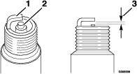
  • Spark plug specification: Champion RC12YC spark plug or equivalent.

    1. Shut off the engine and wait for all moving parts to stop.

    2. Disconnect the wire from the spark plug.

    3. Clean around the spark plug.

    4. Remove the spark plug from the cylinder head.

      Important: Replace a cracked, fouled, or dirty spark plug. Do not clean the electrodes, because grit entering the cylinder can damage the engine.

    5. Set the gap on the plug to 0.76 mm (0.03 inch); refer to .

      g006998
    6. Carefully install the spark plug by hand (to avoid cross threading) until it is hand tight.

    7. Tighten the spark plug an additional 1/2 turn if it is new; otherwise, tighten it an additional 1/8 to 1/4 turn.

      Important: A loose spark plug can become very hot and can damage the engine; overtightening a spark plug may damage the threads in the cylinder head.

    8. Connect the wire to the spark plug.

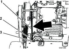
    Checking the Spark Arrester

    (If Equipped)
    Maintenance Service IntervalMaintenance Procedure
    Every 50 hours
  • Check the spark arrester (if equipped).
  • Note: A spark arrester is available as an option. If you require a spark arrester, contact your Authorized Service Dealer.Toro spark arresters are approved by the USDA Forestry Service.

    Warning

    If the engine has been running, the muffler will be hot.

    1. Shut off the engine and wait for all moving parts to stop.

    2. Wait for the muffler to cool.

    3. Remove the spark arrester from the exhaust outlet by removing the screws from the muffler cover and exhaust deflector.

    4. If there are any breaks or holes in the screen, replace the spark arrester.

    5. Use a brush to carefully remove carbon deposits from the spark-arrester screen.

    6. Install the spark arrester on the exhaust outlet.

    Fuel System Maintenance

    Warning

    Fuel-system components are under high pressure. The use of improper components can result in system failure, fuel leakage, and possible explosion.

    Use only approved fuel lines and fuel filters.

    Draining the Fuel Tank

    1. Shut off the engine and wait for it to cool down. Engage the parking brake.

      Note: Drain gasoline from a cold engine only.

    2. Disconnect the wire from the spark plug.

    3. Close the fuel shutoff valve.

    4. Disconnect the fuel line by loosening the tube clamp at the carburetor.

    5. Open the fuel valve by turning the lever to the open position.

    6. Drain the gasoline completely from the tank and fuel line into an approved fuel container.

    7. Close the fuel valve.

    Drive System Maintenance

    Note: The hydrostatic transmission is factory-filled and sealed. It does not require maintenance. For service, contact your Authorized Service Dealer.

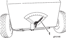
    Checking the Tire Pressure

    Maintenance Service IntervalMaintenance Procedure
    Before each use or daily
  • Check the tire pressure.
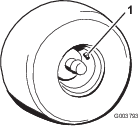
  • Maintain the air pressure in the tires as specified. To get the most accurate reading, check the tires when they are cold.

    Pressure: 165 kPa (24 psi)

    g003793

    Adjusting the Self-Propel Drive

    If the machine creeps either forward or rearward when the engine is on and the self-propel drive bail is in neutral, complete the following procedure:

    1. Shut off the engine, wait for all moving parts to stop, and remove the spark-plug wire.

    2. Raise the cutting blades to the highest position.

    3. Squeeze the self-propel drive bail to the handle until the transmission is fully stroked.

      • If the bail contacts the handle, release the bail. If the bail does not contact the handle, then proceed to step 4.

      • Loosen the top adjustment nut 1 turn, and tighten the bottom adjustment nut.

      • Squeeze the bail to the handle.

      • Repeat this step until there is a gap of up to 3.2 mm (1/8 inch) between the self-propel drive bail and the handle.

      • Once the gap is achieved, proceed with step 4.

        g021266
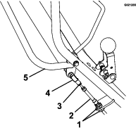
    4. Remove the hairpin and rotate the turnbuckle clockwise 1 full turn.

    5. Install the hairpin and rotate the jam nut against the turnbuckle.

    6. Start the engine and test the adjustment, repeating this procedure as necessary.

    Changing the Hydraulic-Transmission Fluid

    Maintenance Service IntervalMaintenance Procedure
    Every 100 hours
  • Change the hydraulic-transmission fluid.
    1. Shut off the engine, wait for all moving parts to stop, and remove the spark-plug wire. Engage the parking brake.

    2. Remove the transmission from the machine.

    3. Carefully clean the area around the expansion tank and oil-fill port.

      Important: Do not allow any dirt or contamination to enter the hydraulic system.

    4. Remove and retain the oil-fill port fitting, and position the transmission so that the oil drains completely out of the housing.

    5. When all the oil has drained from the transaxle, remove and retain the #10-32 x 1/2 inch self-tapping screw and the ratchet fastener holding the expansion tank to the housing.

    6. Remove the expansion tank, and drain the oil.

      Note: Do not remove the vent cap from the tank.

      Note: Do not remove the tank hose or the O-ring unless a replacement is needed.

    7. Install the expansion tank by first inserting the hose into the tank. Place the tank opening over the O-ring, and push down to ensure a proper seal. Install the #10–32 x 1/2 inch self-tapping screw, and torque it to 25 in-lb (2.8 N⋅m).

    8. Fill the transaxle at the oil-fill port until the oil level is between 1/2 and 1-1/4 inches (between 13 and 32 mm) below the top of the fill port.

      Note: Toro Premium Hydro Oil is recommended. Mobil 1 15W-50 is an acceptable alternative.

    9. Reinstall the oil-fill port fitting.

    Belt Maintenance

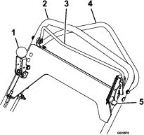
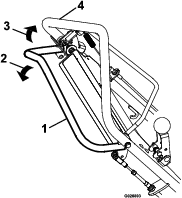
    Removing the Belt Guard

    1. Loosen the 2 capscrews, and 2 flange-head bolts that secure the belt guard to the machine (Figure 24).

      g290695
    2. Remove the belt guard from the machine (Figure 24).

    Installing the Belt Guard

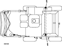
    1. Align the belt guard, capscrews, and flange-head bolts with the holes in the side frame plate and the spring bracket (Figure 25).

      g289447
    2. Assemble the belt guard to the machine with the 2 capscrews, and 2 flange-head bolts (Figure 25).

    3. Torque the capscrews and flange-head bolts to 1378 to 2542 N∙cm (175 to 225 in-lb).

    Checking the Condition of the Belts

    Maintenance Service IntervalMaintenance Procedure
    Every 25 hours
  • Check the condition of the belts.
    1. Shut off the engine, wait for all moving parts to stop, and remove the spark-plug wire. Engage the parking brake.

    2. Remove the belt cover from the left side of the machine.

    3. Check the belts for cracks, frayed edges, burn marks, or any other damage.

    4. If a belt is damaged, replace it.

    5. Check the drive-belt tension; refer to Adjusting the Self-Propel Drive-Belt Tension.

    Adjusting the Self-Propel Drive-Belt Tension

    If the self-propel drive belt squeals during operation (such as when moved from neutral to forward or reverse), tighten the belt as follows:

    1. Shut off the engine, wait for all moving parts to stop, and remove the spark-plug wire.

    2. Raise the cutting blades to the highest position.

    3. Remove and retain the 4 bolts, lock washers, and 2 spacers securing the belt cover to the left side of the machine, and remove the cover.

    4. Check the tension of the belt. It should not flex more than a 6 mm (1/4 inch) with moderate finger pressure applied to the span just above the machine frame (Figure 26).

      g021850
    5. To tighten the belt, loosen the 4 mounting nuts and bolts securing the pulley carriage to the frame, and move the carriage to the left, tightening the belt; then secure the 4 mounting nuts and bolts (Figure 26).

    6. Install the belt cover using the hardware retained in step 3.

    Cutting Blade Maintenance

    Checking and Replacing the Blades

    Maintenance Service IntervalMaintenance Procedure
    Before each use or daily
  • Check the blades for wear or damage.
  • When the cutting blades are worn down and no longer functioning properly, replace them as follows:

    Important: Perform this procedure when the fuel tank is empty or nearly empty.

    1. Shut off the engine, wait for all moving parts to stop, and remove the spark-plug wire. Engage the parking brake.

    2. Turn the fuel shutoff valve to the OFF position, and drain the fuel from the fuel tank; refer to Draining the Fuel Tank.

    3. Remove the 4 bolts, lock washers, and 2 spacers securing the belt cover on the left side of the machine, and remove the cover.

    4. Remove the blade drive belt from the machine.

    5. Tilt the machine rearward until the upper handle rests on the ground, and place a jack stand under the machine.

      Note: If necessary, use 2 people to tilt the machine rearward.

      Caution

      Raising the machine and relying solely on mechanical or hydraulic jacks could be dangerous. The mechanical or hydraulic jacks may not provide enough support or may malfunction allowing the machine to fall, which could cause injury.

      Do not rely solely on mechanical or hydraulic jacks for support. Use adequate jack stands or equivalent support.

    6. Lower the cutting blades to the lowest position.

    7. Spin the cutting blade assembly. It should spin freely. If it makes a grinding noise and is halting, the bearings are worn; replace them when the blades are replaced.

    8. Inspect the blades for damage and wear, and replace them as required.

      Danger

      A worn or damaged blade can break. A piece of the blade could be thrown into the area of the operator or a bystander, resulting in serious personal injury or death.

      • Inspect the blade periodically for wear or damage.

      • Replace a worn or damaged blade.

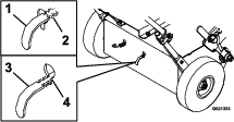
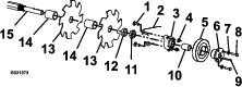
    9. Remove the 4 carriage bolts and locknuts securing the cutting blade assembly (Figure 27), and remove it from the fork mounting bracket.

      g021373
    10. Remove the 2 bolts and washers attaching the pulley to the bearing. Loosen the setscrews on the bearing, and slide the key off the shaft (Figure 27). Remove the bearing and pulley by removing the bearing fasteners from the fork mounting bracket.

    11. Loosen the 2 setscrews located on the flanged bearing, and slide the bearing off the shaft.

    12. Loosen and remove the slicer-shaft nut and pulley spacer from the shaft.

    13. Carefully slide the alternating blades and spacers off the shaft, and replace them as necessary.

    14. Reverse the procedure to install the assembly.

      Note: Rotate each blade 1/6 turn from the previous blade.

      Warning

      Incorrect installation of the blade or components used to retain the blade can be dangerous. Failure to use all original components and assembled as shown could allow a blade or blade component to be thrown out from under the deck resulting in serious personal injury or death.

      Always install Toro blades, blade drivers, and blade bolts as shown.

    15. Return the machine to the upright position.

    16. Connect the wire to the spark plug.

    Seed Gate Maintenance

    Checking the Seed Gate

    Maintenance Service IntervalMaintenance Procedure
    Before each use or daily
  • Check the seed gate.
  • Note: Trapped debris may prevent the seed gate from moving freely.

    1. Shut off the engine, wait for all moving parts to stop, and remove the spark-plug wire. Engage the parking brake.

    2. Check to verify that the seed gate moves freely and is clear of debris.

    3. If the seed gate does not open to the stop when the seeder-control lever is in the ON position, clean the gate assembly; refer to Cleaning the Seed Gate.

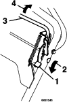
    Adjusting the Seed-Gate Closed Position

    If the seed gate is partially open when the seeder-control lever is in the OFF position, complete the following:

    1. Shut off the engine, wait for all moving parts to stop, and remove the spark-plug wire.

    2. Raise the cutting blades to the highest position.

    3. Pull the seeder-control lever to the OFF position.

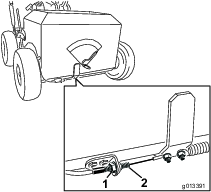
    4. Loosen the nuts on the seed-gate control cable (see Figure 28).

      g013391
    5. Move the cable right to close the seed gate or left to open it.

      Important: Do not tighten the cable to the point the seed gate is tight to the right with extreme tension on the cable as this will damage the gate and the cable. Only adjust it until the openings in the bottom of the seeder are closed.

    6. Tighten the jam nuts and test the seeder-control lever to ensure that the seed gate opens and closes correctly.

    Cleaning

    Washing the Machine

    Wash the machine as needed using water alone or with a mild detergent. You may use a rag when washing the machine

    Important: Do not use brackish or reclaimed water to clean the machine.

    Important: Do not use power-washing equipment to wash the machine. Power-washing equipment may loosen important decals or wash away necessary grease at friction points. Avoid excessive use of water near the control panel and engine.

    Important: Do not wash the machine with the engine running. Washing the machine with the engine running may result in internal engine damage.

    Cleaning the Engine Area

    Maintenance Service IntervalMaintenance Procedure
    Before each use or daily
  • Clean the engine and exhaust area.(Clean the engine and exhaust area more often in dry or dirty conditions.)
  • Caution

    Excessive debris around engine and exhaust area can cause engine and exhaust area to overheat, which can create a fire hazard.

    Clean all debris from engine and exhaust area.

    1. Shut off the engine, wait for all moving parts to stop, and remove the spark-plug wire.

    2. Clean all debris from the engine air-intake screen and around the engine.

    3. Wipe up any excessive grease or oil around the engine.

    Cleaning the Bottom of the Machine

    Maintenance Service IntervalMaintenance Procedure
    Before each use or daily
  • Clean the debris buildup from under the machine.
    1. Shut off the engine, wait for all moving parts to stop, and remove the spark-plug wire.

    2. To ensure the best performance, keep the underside of the machine clean.

      Caution

      The machine may dislodge material from under the housing.

      • Wear eye protection.

      • Stay in the operating position (behind the handle).

      • Do not allow bystanders in the area.

    3. Turn the fuel shutoff valve to the OFF position, and drain the fuel from the fuel tank; refer to Draining the Fuel Tank.

    4. Tilt the machine rearward until the upper handle rests on the ground, and place a jack stand under the machine.

      Note: If necessary, use 2 people to tilt the machine rearward.

    5. Remove the debris with a hardwood scraper or other suitable device. Avoid burrs and sharp edges.

    6. Return the machine to the upright position.

    7. Fill the fuel tank.

    8. Connect the wire to the spark plug.

    Cleaning under the Belt Cover

    Maintenance Service IntervalMaintenance Procedure
    Every 50 hours
  • Clean under the belt cover.
    1. Shut off the engine and wait for all moving parts to stop.

    2. Disconnect the wire from the spark plug.

    3. Remove and retain the 4 bolts, lock washers, and 2 spacers securing the belt cover to the left side of the machine.

    4. Remove the cover, and brush out all the debris around the belt area.

    5. Install the belt cover, and tighten all the hardware.

    6. Connect the wire to the spark plug.

    Cleaning the Seed Gate

    1. Shut off the engine and wait for all moving parts to stop.

    2. Disconnect the wire from the spark plug.

    3. Drain the fuel from the fuel tank; refer to Draining the Fuel Tank.

    4. Tilt the machine rearward until the upper handle rests on the ground, and place a jack stand under the machine.

      Note: If necessary, use 2 people to tilt the machine rearward.

    5. Clean the debris between the frame and the seed gate.

    6. Lubricate the sliding surface between the frame and seed gate with a dry lubricant.

    7. Return the machine to the upright position.

    8. Fill the fuel tank.

    9. Connect the wire to the spark plug.

    Storage

    Storage Safety

    • Park the machine on a level surface, shut off the engine, wait for all moving parts to stop, engage the parking brake, and allow the machine to cool before storing it.

    • Do not store the machine or fuel near flames or drain the fuel indoors.

    Storing the Machine

    1. Raise the cutting blades, stop the machine, shut off the engine, and disconnect the spark-plug wire.

    2. Remove dirt and grime from the entire machine.

      Important: You can wash the machine with mild detergent and water. Do not pressure-wash the machine. Avoid excessive use of water, especially near the engine.

    3. Service the air cleaner; refer to Servicing the Air Cleaner.

    4. Change the engine oil; refer to Changing the Engine Oil.

    5. Grease the slicer-shaft bearings; refer to Lubricating the Slicer-Shaft Bearings.

    6. For storage over 30 days, prepare the machine as follows:

      1. Add a petroleum-based stabilizer/conditioner to fuel in the tank. Follow mixing instructions from stabilizer manufacturer. Do not use an alcohol-based stabilizer (ethanol or methanol).

        Note: A fuel stabilizer/conditioner is most effective when mixed with fresh fuel and used at all times.

      2. Run the engine until it stops from running out of fuel.

      3. Choke the engine.

      4. Start and run the engine until it will not start again.

      5. Dispose of fuel properly. Recycle the fuel according to local codes.

      Important: Do not store fuel containing stabilizer/conditioner longer than the duration recommended by the fuel stabilizer manufacturer.

    7. Check and tighten all bolts, nuts, and screws. Repair or replace any part that is damaged.

    8. Paint all scratched or bare metal surfaces with paint from an Authorized Service Dealer.

    9. Store the machine on a level surface in a clean, dry garage or storage area.

    10. Cover the machine to protect it and keep it clean.

    Removing the Machine from Storage

    1. Check and tighten all fasteners.

    2. Inspect the spark plug and replace it if it is dirty, worn, or cracked; refer to the engine owner’s manual.

    3. Install the spark plug until it is hand-tight, then an additional 1/2 turn if it is new; otherwise, tighten it an additional 1/8 to 1/4 turn.

    4. Perform any needed maintenance procedures; refer to .

    5. Check the engine-oil level; refer to Checking the Engine-Oil Level.

    6. Fill the fuel tank with fresh fuel; refer to Adding Fuel.

    7. Connect the wire to the spark plug.

    Troubleshooting

    ProblemPossible CauseCorrective Action
    The engine does not start, starts hard, or fails to keep running.
    1. The fuel tank is empty.
    2. The fuel-shutoff valve is closed.
    3. There is dirt in fuel filter.
    4. Dirt, water, or stale fuel is in the fuel system.
    5. The air cleaner is dirty.
    6. The spark plug is old or improperly gapped.
    7. The spark-plug wire is not connected.
    1. Fill the fuel tank.
    2. Open the fuel-shutoff valve.
    3. Replace the fuel filter.
    4. Contact an Authorized Service Dealer.
    5. Clean or replace the air-cleaner elements.
    6. Adjust or replace the spark plug.
    7. Check the spark-plug wire connection.
    The engine loses power.
    1. The engine load is excessive.
    2. The air cleaner is dirty.
    3. The oil level in the crankcase is low.
    4. The cooling fins and air passages for the engine are plugged.
    5. Dirt in fuel filter.
    6. Dirt, water, or stale fuel is in the fuel system.
    1. Reduce the ground speed or slicing depth.
    2. Clean or replace the air-cleaner elements.
    3. Add oil to the crankcase.
    4. Remove the obstructions from the cooling fins and air passages.
    5. Replace the fuel filter.
    6. Contact an Authorized Service Dealer.
    The engine overheats.
    1. The engine load is excessive.
    2. The oil level in the crankcase is low.
    3. The cooling fins and air passages for the engine are plugged.
    1. Reduce the ground speed or slicing depth.
    2. Add oil to the crankcase.
    3. Remove the obstructions from the cooling fins and air passages.
    The machine pulls to the left or the right.
    1. The tire pressure in the drive tires is not correct.
    1. Adjust the tire pressure in the drive tires.
    The machine does not drive.
    1. The drive or pump belt is worn, loose, or broken.
    2. The drive or pump belt is off a pulley.
    3. The transmission oil level is low.
    4. The self-propel cable needs adjustment or is broken.
    1. Change the belt.
    2. Change the belt.
    3. Add hydraulic oil to the transmission.
    4. Adjust or replace the cable.
    There is abnormal vibration.
    1. The blade(s) is/are bent.
    2. The engine mounting bolts are loose.
    3. The engine pulley or idler pulley is loose.
    4. The engine pulley is damaged.
    5. The belt is damaged.
    1. Install new blade(s).
    2. Tighten the engine mounting bolts.
    3. Tighten the appropriate pulley.
    4. Contact an Authorized Service Dealer.
    5. Install a new belt.