Introduction

This engine is not equipped with a spark arrester. It is a violation of California Public Resource Code Section 4442 or 4443 to use or operate the engine on any forest-covered, brush-covered, or grass-covered land unless the engine is equipped with a spark arrester, as defined in Section 4442, maintained in effective working order or the engine is constructed, equipped, and maintained for the prevention of fire.

If you require a spark arrester, contact your Authorized Service Dealer. Genuine Toro spark arresters are approved by the USDA Forestry Service.

Important: These installation instructions contain engine operation and maintenance information that supersedes the engine operation and maintenance procedures in your machine Operator’s Manual.Before operating or maintaining the machine or engine, always refer to the operating and safety instructions in your Operator’s Manual.Save these instructions.

Important: The engine warranty is provided by the engine manufacturer. Please refer to the engine manufacturer's warranty and emissions system warranty included in the literature packet. That warranty applies only to the engine. It does not expand or otherwise alter any express or implied warranty terms or warranty period that may apply to the product into which the engine is installed.

Warning

CALIFORNIA

Proposition 65 Warning

The engine exhaust from this product contains chemicals known to the State of California to cause cancer, birth defects, or other reproductive harm.

Safety

Safety and Instructional Decals

Graphic

Safety decals and instructions are easily visible to the operator and are located near any area of potential danger. Replace any decal that is damaged or missing.

decal130-8322
decal133-8062
decal138-2138

Installation

Note: If the machine is equipped with an incandescent light kit, you may need to order a new kit; contact your authorized Toro distributor for more information.

Removing the Existing Engine

Important: Retain all removed parts for reuse unless otherwise noted.

  1. Drain the gearbox; refer to your Operator’s Manual.

  2. Remove and retain the nuts attaching the engine to the gearbox (Figure 5).

  3. Support the gearbox from below so that it does not fall when you remove the engine.

  4. Remove the wire harness from the engine.

  5. Remove the interlock module and fasteners (Figure 1).

    g262138
  6. Remove the throttle-control cable from the engine, but not from the control console.

  7. Remove the engine mounting bolts, washers, and nuts.

  8. Remove the engine from the traction unit.

  9. Remove and retain all engine output shaft hardware (Figure 2).

    g274554
  10. Clean the frame and check for damage or wear.

  11. Check the gearbox gasket for damage or wear; replace the gasket if it is damaged.

Preparing the New Engine

  1. Remove the air filter and cover; refer to Servicing the Air Cleaner.

  2. Remove the throttle control pivot nut (Figure 3).

  3. Remove the short spring and the governor spring (Figure 3).

  4. Remove the nut, pressure plate, wave washer, and throttle control from the engine (Figure 3).

    g274607
  5. Remove the e-clip from the bottom of the cable clamp and remove the cable clamp from the throttle control.

  6. Remove the screw from the wide clamp and remove the wide clamp from the throttle control.

  7. Install the wide clamp and the cable clamp in the new locations on the throttle control with the screw and e-clip (Figure 4).

    Important: Ensure that the cable clamp is oriented with the wire opening facing toward the wide clamp.

    g274608
  8. Install the throttle control, wave washer, and pressure plate to the engine (Figure 4).

  9. Install and lightly tighten the nut to secure the throttle control to the engine (Figure 4).

    Note: The lever should move back and forth smoothly and easily.

  10. Install the springs to the throttle control and test the return (Figure 4).

    Note: There should be enough tension in the spring to return the throttle control to the default position; if the control does not return, loosen the nut until it does.

Installing the New Engine

Parts needed for this procedure:

Engine1
Nut4
Self-tapping screw1
Set screw4
  1. Apply medium-strength thread-locking compound (such as Blue Loctite® 242) to the threads of the 4 set screws and install them to the engine (Figure 5).

  2. Install the existing engine output shaft components to the engine (Figure 5).

    Note: Apply anti-seize compound to the key and engine drive shaft before installing.

  3. Install the interlock module to the wire harness bracket with the included self-tapping screw (Figure 5).

    Note: The wire harness bracket is already installed on the engine.

  4. Install the gearbox gasket to the set screws on the crankcase cover.

  5. Position the engine on the engine mount with the shaft facing toward the gearbox assembly.

  6. Slide the engine toward the gearbox while guiding the drive gear into gearbox input area.

    Note: You may need to turn the crankshaft to mesh the engine gear teeth with the gearbox input gear.

  7. Install and finger-tighten the 4 flange nuts that secure the gearbox assembly to the set screws on the engine crankcase cover.

  8. Install the 4 previously removed engine bolts and washers through the engine and engine mount.

  9. Secure the engine by installing 4 nuts on the engine bolts from the underside of the engine mount.

  10. Fully tighten the flange nuts that secure the gearbox assembly to the engine and the nuts that secure the engine to the engine mount.

    g274576

Installing the Wire Harness and Throttle Cable

Parts needed for this procedure:

Cable ties4
Throttle cable1
  1. Install the wire harness to the interlock connector on the wire harness bracket and clip the wire harness to the bracket.

    g274613
  2. Mount the green ground wire using the cowling bolt under the fuel tank, and connect the red wire to the engine connector as shown in Figure 7.

    Note: Apply skin-over grease to the bolt and ground lug terminal.

    g274609
  3. Route the harness up the left side of the handle (Figure 8).

  4. Connect the engine switch to the wire harness (Figure 8).

    Note: Connect the wire harness to the hourmeter (if equipped).

  5. Secure the wire harness under the console cover with a snap clip and cable ties as needed.

  6. If the machine has a light kit, use the wire harness adapter to install the main wire harness to the engine.

  7. Attach the cables and wire harness to the handles using the 4 new cable-ties (Figure 8).

    g262107
  8. Loosen the screw on top of the cable clamp.

  9. Install the straight end of the throttle cable housing through the wide clamp and the throttle cable through the cable clamp.

    g274612
  10. Tighten the screw on top of the cable clamp to secure the connection to the throttle control.

  11. Route the cable beneath the front of the engine and through the cable clip (Figure 10).

  12. Remove the cable clip from the bottom of the front-right engine bolt and install it on the top (Figure 10).

    g274716
  13. Install the air filter and cover; refer to Servicing the Air Cleaner.

Lubricating and Adjusting the Machine

  1. Lubricate the machine according to the instructions in your Operator’s Manual.

  2. Fill the gearcase with oil according to the instructions in your Operator’s Manual.

  3. Fill the engine crankcase with oil according to the instructions in your Operator’s Manual.

  4. Adjust the engine speed to the following specifications:

    High idle (no load)3300 to 3500 rpm
    Low idle (no load)1800 to 2000 rpm

Product Overview

g265059

Choke Control

The choke control is located on the side of the engine (Figure 11); you use it to help start a cold engine

Note: Do not start or run a warm engine with the choke in the CLOSED position.

  • Move the choke lever all the way to the left (away from starter handle) to set the choke to the CLOSED position.

  • Move the choke lever all the way to the right (toward starter handle) to set the choke to the OPEN position.

Fuel-Shutoff Valve

The fuel-shutoff valve is located on the side of the engine below the choke control (Figure 11).

Note: Close the fuel-shutoff valve when the machine is not used for a few days, during transport to and from the job site, or when the machine is parked inside a building; refer to Opening and Closing the Fuel-Shutoff Valve.

Operation

Fuel Specifications

Fuel tank capacity: 2.0 L (0.59 US gallons)

Recommended fuel: Unleaded gasoline with an octane rating of 87 or higher ((R+M)/2 rating method)

Ethanol: Gasoline with up to 10% ethanol (gasohol) or 15% MTBE (methyl tertiary butyl ether) by volume is acceptable. Ethanol and MTBE are not the same. Gasoline with 15% ethanol (E15) by volume is not approved for use.

  • Never use gasoline that contains more than 10% ethanol by volume, such as E15 (contains 15% ethanol), E20 (contains 20% ethanol), or E85 (contains up to 85% ethanol).

  • Do not use gasoline containing methanol.

  • Do not store fuel either in the fuel tank or fuel containers over the winter unless a fuel stabilizer is used.

  • Do not add oil to gasoline.

  • For best results, use only clean, fresh (less than 30 days old) fuel.

  • Using unapproved gasoline may cause performance problems and/or engine damage, which may not be covered under the warranty

Using Stabilizer/Conditioner

Use a fuel stabilizer/conditioner in the machine to provide the following benefits:

Important: Do not use fuel additives containing methanol or ethanol.

Add the correct amount of fuel stabilizer/conditioner to the gasoline.

Note: A fuel stabilizer/conditioner is most effective when mixed with fresh gasoline. To minimize the chance of varnish deposits in the fuel system, use fuel stabilizer at all times.

Filling the Fuel Tank

Danger

In certain conditions, fuel is extremely flammable and highly explosive. A fire or explosion from fuel can burn you and others and can damage property.

  • Fill the fuel tank outdoors, in an open area, when the engine is cold. Wipe up any fuel that spills.

  • Never fill the fuel tank inside an enclosed trailer.

  • Do not fill the fuel tank completely full. Add fuel to the fuel tank until the level is 6 to 13 mm (1/4 to 1/2 inch) below the bottom of the filler neck. This empty space in the tank allows fuel to expand.

  • Never smoke when handling fuel, and stay away from an open flame or where fuel fumes may be ignited by a spark.

  • Store fuel in an approved container and keep it out of the reach of children. Never buy more than a 30-day supply of fuel.

  • Do not operate without entire exhaust system in place and in proper working condition.

Danger

In certain conditions during fueling, static electricity can be released, causing a spark which can ignite the fuel vapors. A fire or explosion from fuel can burn you and others and can damage property.

  • Always place fuel containers on the ground away from your vehicle before filling.

  • Do not fill fuel containers inside a vehicle or on a truck or trailer bed because interior carpets or plastic truck-bed liners may insulate the container and slow the loss of any static charge.

  • When practical, remove equipment from the truck or trailer and fuel it on the ground. If this is not possible, then fuel such equipment with a portable container rather than from a fuel-dispenser nozzle.

  • If you must use a fuel-dispenser nozzle, keep the nozzle in contact with the rim of the fuel tank or container opening at all times until fueling is complete.

Warning

Fuel is harmful or fatal if swallowed. Long-term exposure to vapors can cause serious injury and illness.

  • Avoid prolonged breathing of vapors.

  • Keep your face away from the nozzle and fuel tank or conditioner bottle opening.

  • Avoid contact with skin; wash off spills with soap and water.

  1. Park the machine on a level surface and shut off the engine.

  2. Allow the engine to cool.

  3. Clean around the fuel-tank cap and remove it (Figure 12).

    g265976
  4. Fill the tank with fuel until the level is just inside the mesh filter basket.

    Do not fill into the filler neck of the tank.

    Important: Do not fill the tank more above the filler mesh because the fuel needs room to expand.

  5. Install the fuel-tank cap securely.

  6. Wipe up any spilled fuel.

Opening and Closing the Fuel-Shutoff Valve

Control fuel flow to the engine with the fuel-shutoff valve as follows:

  • To open the fuel valve, turn the fuel-shutoff valve handle toward the recoil starter handle (Figure 13).

  • To shut the fuel valve, turn the fuel-shutoff valve handle away from the recoil starter handle (Figure 13).

    g265993

Maintenance

Important: Refer to your engine owner’s manual for additional maintenance procedures.

Recommended Maintenance Schedule(s)

Maintenance Service IntervalMaintenance Procedure
After the first 20 hours
  • Change the engine oil.
  • Before each use or daily
  • Check the engine-oil level.
  • Inspect the air-filter elements.
  • Every 50 hours
  • Clean the air-filter elements.
  • Every 100 hours
  • Change the engine oil.
  • Inspect and adjust the spark plug; replace it if necessary.
  • Every 300 hours
  • Replace the paper filter element (More frequently in dusty operating conditions).
  • Replace the spark plug.
  • Preparing the Machine for Maintenance

    Warning

    While you are maintaining or adjusting the machine, someone could start the engine. Accidentally starting the engine could seriously injure you or other bystanders.

    Remove the key from the ignition, engage parking brake, and pull the wire(s) off the spark plug(s) before you do any maintenance. Also push the wire(s) aside so it does not accidentally contact the spark plug(s).

    Perform the following before servicing, cleaning, or making any adjustments to the machine.

    1. Park the machine on a level surface.

    2. Shut off the engine and remove the key from the machine (if equipped).

    3. Engage the parking brake.

    4. Wait for all moving parts to stop and allow the engine to cool before servicing or storing.

    5. Disconnect the spark-plug wire (Figure 14).

      g265998

    Servicing the Engine Oil

    Fill the crankcase with approximately 0.56 L (19 fl oz) of the proper viscosity oil before starting. The engine uses a high-quality oil that has the American Petroleum Institute (API) service classification of SJ or higher. Select the proper oil viscosity (weight) based on the ambient temperature. Figure 15 illustrates the temperature/viscosity recommendations.

    g013375

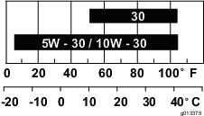
    Note: Multi-grade oils (5W-20, 10W-30 and 10W-40) increase oil consumption. Check the engine-oil level more frequently when you use these oils.

    Checking the Engine-Oil Level

    Maintenance Service IntervalMaintenance Procedure
    Before each use or daily
  • Check the engine-oil level.
  • The ideal time to check the engine-oil level is when the engine is cool or before you have started the engine for the day. If you have already ran the engine, allow the oil to drain back down to the sump for at least 10 minutes before you check the engine-oil level.

    1. Shut off the engine and wait for all moving parts to stop; refer to Preparing the Machine for Maintenance.

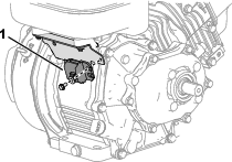
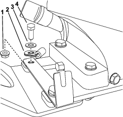
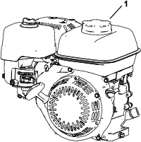
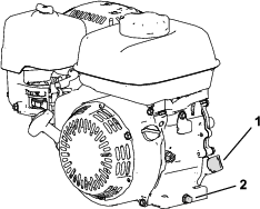
    2. Position the machine so that the engine is level, and clean the area around the oil-fill tube (Figure 16).

      g266053
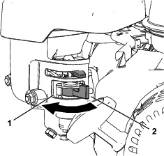
    3. Remove the dipstick by rotating it counterclockwise.

    4. Remove the dipstick and wipe the end clean.

    5. Insert the dipstick fully into the oil-fill tube, but do not thread it in.

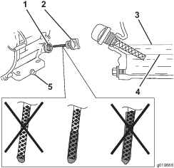
    6. Remove the dipstick and check the engine-oil level (Figure 17).

      g019686
    7. If the engine-oil level is incorrect, add or drain oil to correct the level; refer to Changing the Engine Oil.

    Changing the Engine Oil

    Maintenance Service IntervalMaintenance Procedure
    After the first 20 hours
  • Change the engine oil.
  • Every 100 hours
  • Change the engine oil.
  • Warning

    Oil may be hot after the engine has been run, and contact with hot oil can cause severe personal injury.

    Avoid contacting the hot engine oil when you drain it.

    1. Shut off the engine and wait for all moving parts to stop; refer to Preparing the Machine for Maintenance.

    2. Raise the engine off the ground and place a pan under the drain plug to catch the oil.

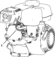
    3. Remove the drain plug (Figure 16).

    4. When the oil has drained completely, lower the engine to the ground, replace the drain plug and washer, and torque the plug to 18 N⋅m (13 ft-lb).

      Note: Dispose of the used oil at a certified recycling center.

    5. Remove the dipstick, and slowly pour oil into the oil-fill hole until the oil is at the correct level.

    6. Ensure that the oil is at the correct level on the dipstick; refer to Checking the Engine-Oil Level.

    7. Replace and secure the dipstick.

    8. Wipe up any spilled oil.

    9. Connect the wire to the spark plug.

    Servicing the Air Cleaner

    Maintenance Service IntervalMaintenance Procedure
    Before each use or daily
  • Inspect the air-filter elements.
  • Every 50 hours
  • Clean the air-filter elements.
  • Every 300 hours
  • Replace the paper filter element (More frequently in dusty operating conditions).
  • Important: Do not operate the engine without the air filter assembly; extreme engine damage will occur.

    1. Shut off the engine and wait for all moving parts to stop; refer to Preparing the Machine for Maintenance.

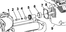
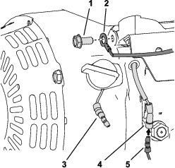
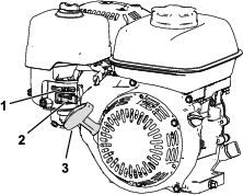
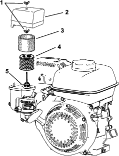
    2. Remove the wingnut securing the air-cleaner cover (Figure 18).

    3. Remove the air-cleaner cover.

      Note: Ensure that no dirt or debris from the air-cleaner cover fall into the base.

    4. Remove the foam and paper elements from the base.

    5. Remove the foam element from the paper element.

    6. Inspect the foam and paper elements; replace them if they are damaged or excessively dirty.

      g265999
    7. Clean the paper element by tapping it gently to remove the dirt.

      Note: Do not try to brush dirt off the paper element; brushing forces the dirt into the fibers. Replace the element if tapping it fails to remove the dirt.

    8. Clean the foam element in warm, soapy water or in a nonflammable solvent.

      Note: Do not use gasoline to clean the foam element because it could create a risk of fire or explosion.

    9. Rinse and dry the foam element thoroughly.

    10. Wipe dirt from the base and the cover with a moist rag.

      Note: Ensure that dirt and debris do not enter the air duct leading to the carburetor.

    11. Install the air-cleaner elements and ensure that they are properly positioned. Install the lower wing nut.

    12. Install the cover and install the upper wing nut to secure it.

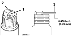
    Servicing the Spark Plug

    Maintenance Service IntervalMaintenance Procedure
    Every 100 hours
  • Inspect and adjust the spark plug; replace it if necessary.
  • Every 300 hours
  • Replace the spark plug.
  • Use an NGK BPR6ES spark plug or equivalent.

    1. Shut off the engine and wait for all moving parts to stop; refer to Preparing the Machine for Maintenance.

    2. Clean around the spark plug.

    3. Remove the spark plug from the cylinder head.

      Important: Replace a cracked, fouled, or dirty spark plug. Do not sand blast, scrape, or clean the electrodes because engine damage could result from grit entering the cylinder.

    4. Set the gap on the plug to 0.7 to 0.8 mm (0.028 to 0.031 inch)

      g000533
    5. Carefully install the spark plug by hand (to avoid cross threading) until it is hand tight.

    6. Tighten the spark plug an additional 1/2 turn if it is new; otherwise, tighten it an additional 1/8 to 1/4 turn.

      Important: A loose spark plug can become very hot and can damage the engine; overtightening a spark plug may damage the threads in the cylinder head.

    7. Connect the wire to the spark plug.