Important: The Power Converter Kit is required to use the cab on a Workman GTX Electric utility vehicle. Contact your authorized Toro distributor for more information.
Important: The Spring Kit is required to use the cab on a Workman GTX utility vehicle. The Spring Kit should be installed only by qualified Toro Service Technicians using approved tools. Improper removal, disassembly, or installation of the spring assembly poses a danger to you and bystanders. Please contact your authorized Toro distributor for the appropriate tools and proper installation of this kit.
Safety
Warning
The compressed spring in the spring and shock assembly represents a stored-energy hazard. If the spring is not properly retained during compression or removal, it can injure you and/or bystanders.
-
Always use the approved Toro spring-compression tool to compress the spring in a secure position when removing the retention collar.
-
Always use care when removing pressure from the compressed spring.
Safety and Instructional Decals
 |
Safety decals and instructions are easily visible to the operator and are located near any area of potential danger. Replace any decal that is damaged or missing. |


Setup
Preparing the Machine
-
Park the machine on a level surface, set the parking brake, shut off the engine, and remove the key.
-
Raise the bed until the bed prop rod is fully engaged; refer to the Operator’s Manual for the machine.
-
Remove the seat base.
-
Disconnect the negative battery cable; refer to your Operator’s Manual.
Removing the Strut Assembly
-
Remove the front wheel.
-
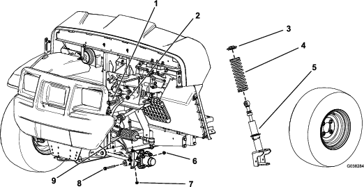
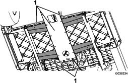
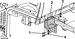
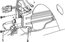
Remove the hex-head bolt (3/8 x 4-3/4 inches) and flange nut (3/8 inch) from the spindle (Figure 1).
-
Remove the hex-head bolt (3/8 x 3-1/2 inches) and flange nut (3/8 inch) from the control arm (Figure 1).
-
Remove the hex-head bolt (1/2 x 2-1/4 inches) and locknut (1/2 inch) securing the strut assembly to the upper frame (Figure 1).
-
Remove the strut assembly (Figure 1).
Note: Repeat this procedure for the other side of the machine.
Installing the Springs
Parts needed for this procedure:
| Spring | 2 |
Use an approved Toro spring-compression tool to remove and install springs of the strut assembly. Contact your authorized Toro distributor.
-
Place the strut assembly into the compression tool and use the tool to compress the spring.
-
While the spring is compressed, remove the collar.
-
Remove the spring from the strut assembly (Figure 1).
-
Install the new spring over the existing strut assembly (Figure 1).
-
Using the Toro spring-compression tool, compress the spring.
-
While the spring is compressed, install the collar.
-
Carefully release pressure on the spring, allowing it to seat on the collar.
-
Remove the strut assembly from the compression tool.
Note: Repeat this procedure for the other side of the machine.
Installing the Strut Assembly
-
Install strut assembly to the machine.
-
Secure the upper portion of the strut assembly to the frame using the upper, hex-head bolt (1/2 x 2-1/4 inches) and locknut (1/2 inch) as shown in Figure 1.
-
Torque the hex-head bolt (1/2 x 2-1/4 inches) to 91 to 113 N∙m (67 to 83 ft-lb).
-
Install the hex-head bolt (3/8 x 4-3/4 inches) and flange nut (3/8 inch) to the spindle (Figure 1).
-
Torque the hex-head bolt (3/8 x 4-3/4 inches) to 37 to 45 N∙m (27 to 33 ft-lb).
-
Secure the lower portion of the strut assembly to the control arm using the hex-head bolt (3/8 x 3-1/2 inches) and flange nut (3/8 inch) as shown in Figure 1.
-
Torque the hex-head bolt (3/8 x 3-1/2 inches) to 37 to 45 N∙m (27 to 33 ft-lb).
-
Install the front wheel.
Note: Repeat this procedure for the other side of the machine.
Installing the Supports
Parts needed for this procedure:
| Floor-plate support | 2 |
| Flange-head bolt (5/16 x 1-1/4 inches) | 16 |
| Flange nut (5/16 inch) | 16 |
| Left cab support | 1 |
| Right cab support | 1 |
| Hex-head bolt (3/8 x 1-1/4 inch) | 4 |
| Flange nut (3/8 inch) | 4 |
| Washer (3/8 inch) | 4 |
-
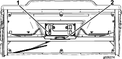
Remove the 4 screws (1/4 x 1-1/4 inches) and 4 nuts (1/4 inch) from the floor plate (Figure 2).
-
Use a floor jack under the frame to support the front of the machine (Figure 3).
-
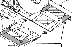
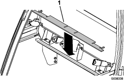
Remove 1 of the existing floor-plate supports (Figure 4).
Important: Do not remove both of the existing floor-plate supports simultaneously.
-
Install a new floor-plate support using 8 flange-head bolts (5/16 x 1-1/4 inches) and 8 flange nuts (5/16 inch) as shown in Figure 5.
Note: Torque the flange-head bolts (5/16 x 1-1/4 inches) to 34 N∙m (25 ft-lb).
-
Remove the other existing floor-plate support (Figure 4).
-
Install the other new floor-plate support using 8 flange-head bolts (5/16 x 1-1/4 inches) and 8 flange nuts (5/16 inch) as shown in Figure 5.
-
Install the previously removed 4 screws (1/4 x 1-1/4 inches) and 4 nuts (1/4 inch) into the floor plate (Figure 2).
-
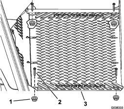
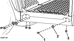
Using the new floor-plate supports as a guide, drill 3 holes (3/8-inch diameter) into each floor plate (Figure 6).
Important: Drill only the front 2 holes on the new floor-plate supports and the farthest, rear hole; as shown in Figure 6.
-
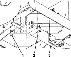
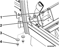
Loosely attach the left and right cab supports to the machine using the hex-head bolts (3/8 x 1-1/4 inch), washers (3/8 inch), and flange nuts (3/8 inch) as shown in Figure 7.
Note: Do not tighten the bolts at this time.
Installing the Cab
Parts needed for this procedure:
| Cab frame | 1 |
| Back foam seal | 1 |
| Back foam seal carpet | 1 |
| Flange-head bolt (5/16 x 1-1/4 inches) | 4 |
| Flange nut (5/16 inch) | 4 |
| Flat washer (5/16 inch) | 4 |
| Support plate | 2 |
| Right, front foam seal | 1 |
| Left, front foam seal | 1 |
| Upper, rear foam seal | 1 |
| Foam seal | 2 |
| Hex-head bolt (3/8 x 1-1/4 inches) | 6 |
| Flange nut (3/8 inch) | 6 |
| Washer (3/8 inch) | 6 |
-
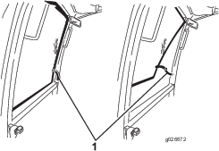
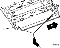
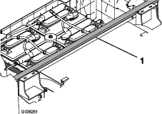
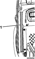
Remove the backing from the back foam seal and attach the seal to the machine as shown in Figure 8.
Important: Ensure that the underside of the back foam seal with the adhesive faces the top of the rail surface.
-
Remove the seat base.
-
Remove the 3 screws and 3 nuts securing the left handhold, and remove it (Figure 9).
-
Install the front sealing foam if it is not already installed (Figure 10).
Note: Ensure that you install the front sealing foam onto the cab before you install the cab onto the machine.
-
Lift the cab frame using the lift points and place it on the machine (Figure 11).
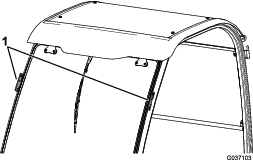
-
Secure the sides of the cab frame to the machine using 6 hex-head bolts (3/8 x 1-1/4 inches), 6 washers (3/8 inch), and 6 flange nuts (3/8 inch) as shown in Figure 12.
Note: Torque the hex-head bolts (3/8 x 1-1/4 inches) to 58 N∙m (43 ft-lb).
-
Secure the back of the cab frame to the left and right supports using 4 flange-head bolts (5/16 x 1-1/4 inches), 2 support plates, 4 flat washers, and 4 flange nuts (5/16 inch) as shown in Figure 13.
Note: Torque the bolts to 34 N∙m (25 ft-lb).
-
Tighten the left and right supports, and torque the bolts to 58 N∙m (43 ft-lb) as shown in Figure 7.
-
Install the previously removed left handhold using the 3 screws and 3 nuts (Figure 9).
-
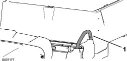
Install the upper, rear foam seal (Figure 14).
-
Install the seat base.
Note: You may need to position the 2 center seat-belt anchors to allow the seat to drop into place. Loosen the 2 locknuts (7/16 inch) on the 2 center seat-belt anchors, and tighten the 2 locknuts (7/16 inch) to 72 to 88 N∙m (53 to 65 ft-lb) after adjusting the position.
-
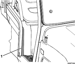
Remove the backing from the right, front and left, front foam seals and attach the seals to the machine (Figure 15).
-
Remove the backing from the foam seal and attach the seal to the right side of the machine (Figure 16).
Routing the Wire Harness
Parts needed for this procedure:
| Fuse block | 1 |
| Hex-washer head screw (#10 x 3/4 inch)—for 2019 and after electric machines only | 2 |
| Serrated nut (#10)—for 2019 and after electric machines only | 2 |
| Self-tapping screw—for 2019 and after gasoline machines only | 2 |
| Fuse (15 A) | 1 |
For Electric Machines
Important: The Power Converter Kit is required to use the cab on a Workman GTX Electric utility vehicle. Contact your authorized Toro distributor for more information.
-
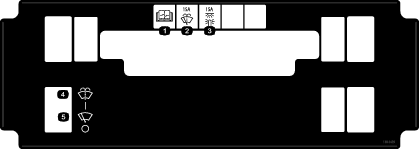
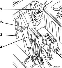
Install the new fuse block as follows:
-
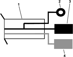
For 2019 and after machines, connect the female connector on the harness to the new fuse block (Figure 18).
-
Connect the large connector on the new fuse block to the optional power cable on the existing fuse block (Figure 17).
-
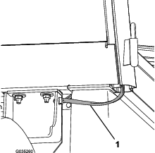
Route the wire harness behind the cab and under the seat, and secure the clip on the wire harness to the side panel (Figure 19).
-
Install the black ground wire to the ground wire on the Power Converter Kit wire harness (Figure 20).
Note: The black terminal ring is not used.
-
Install the red power wire to the power wire on the Power Converter Kit wire harness (Figure 20).
-
Connect the remaining wire to the fused wire on the new fuse block (Figure 17).
-
Lower the bed and connect the battery; refer to the Operator’s Manual.
-
Install the previously removed seat base.
For Gasoline/Petrol or EFI Machines
-
Install the new fuse block as follows:
-
Connect the large connector on the new fuse block to the optional power cable on the existing fuse block (Figure 17).
-
Route the wire harness behind the cab and under the seat, and secure the clip on the wire harness to the side panel (Figure 19).
-
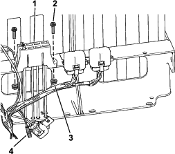
Install the black terminal ring to the ground block on the machine (Figure 22).
-
Install the red power wire into an empty slot on the machine fuse block (Figure 22).
Note: Install an additional fuse block if there are no remaining slots open in a fuse block.
-
Connect the remaining wire to the fused wire on the new fuse block (Figure 17).
-
Lower the bed and connect the battery; refer to the Operator’s Manual.
-
Install the previously removed seat base.
Product Overview
Control Panel
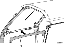
Windshield Latch
Lift up on the latches to open the windshield (Figure 24). Press down on the latch to lock the windshield in the open position. Pull out and down on the latch to close and secure the windshield.