


Maintenance
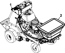
Note: Determine the left and right sides of the machine from the normal operating position.
Warning
If you leave the key in the switch, someone could accidently start the engine and seriously injure you or other bystanders.
Remove the key from the switch, engage parking brake, and pull the wire(s) off the spark plug(s) before you do any maintenance to the machine or attachment. Also push the wire(s) aside so it does not accidentally contact the spark plug(s).
Recommended Maintenance Schedule(s)
| Maintenance Service Interval | Maintenance Procedure |
|---|---|
| Before each use or daily |
|
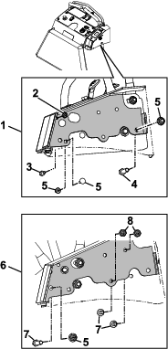
Checking for Loose Hardware
| Maintenance Service Interval | Maintenance Procedure |
|---|---|
| Before each use or daily |
|
-
Shut off the engine, remove the key, wait for all moving parts to stop, and engage the parking brake.
-
Visually inspect the machine for any loose hardware or any other possible problem. Tighten any loose hardware or correct the problem before operating the machine.
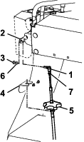
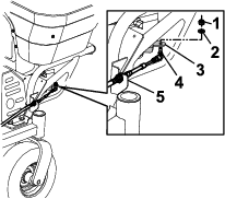
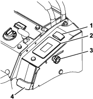
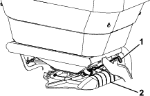
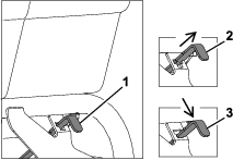
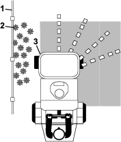
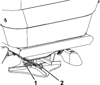
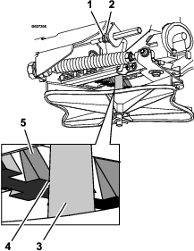
Adjusting the Spreader Pattern Control Cable
-
Shut off the engine, remove the key, wait for all moving parts to stop, and engage the parking brake.
-
Close the granular gate.
-
Ensure that the spread pattern control handle is pushed down and locked at the control panel.
-
Loosen the jam nut at the end of the cable.
-
Pull the linkage rod until there is 3.2 mm (1/8 inch) gap between the ramp tooth and the impeller shaft.
-
Tighten the jam nut.
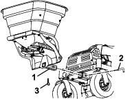
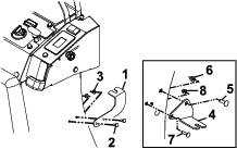
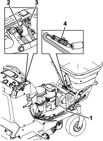
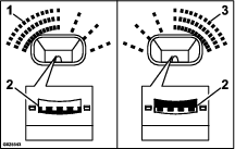
Adjusting the Gate Closure
-
If the gate arm is not fully closing, adjust the control cable at the knob located on the cable mount bracket or the nuts located on either side of the hopper bracket.
-
Continue to adjust until the gate can be fully closed; tighten all components.
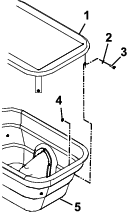
Cleaning
Cleaning Debris from the Machine
| Maintenance Service Interval | Maintenance Procedure |
|---|---|
| Before each use or daily |
|
-
Shut off the engine, remove the key, wait for all moving parts to stop, and engage the parking brake.
-
Clean off any debris or buildup on the machine, especially the impeller.