| Maintenance Service Interval | Maintenance Procedure |
|---|---|
| After each use |
|
Safety
Rear Discharge or Mulch Grass
Warning
Without the grass deflector mounted in place, you and others are exposed to blade contact and thrown debris. Contact with rotating mower blade(s) and thrown debris will cause injury or death.
-
Never remove the grass guard from the mower because the grass guard routes material down toward the turf. If the grass guard is ever damaged, replace it immediately.
-
Never put your hands or feet under the mower.
-
Never try to clear the discharge area or mower blades unless you engage the parking brake, disengage the power take off (PTO) lever, shutoff the engine, remove the ignition key, and wait for all motion to stop. Also pull the wire off the spark plug(s).
Ensure that the mower has the rear grass guard to disperses clippings to the rearward and down toward the turf, while in rear discharge mode.
To mulch grass clippings, install the baffles on the mower deck as instructed in the following procedures.
Installation
Note: Recycler blades (sold separately) are required to install this kit; refer to the Parts Catalog for your machine.
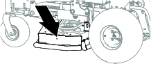
Preparing the Mower
Note: Determine the left and right sides of the machine from the normal operating position.
-
Park the machine on a level surface; disengage the cutting unit(s) and lower the cutting unit; engage the parking brake; shut off the engine and remove the key; and wait for all movement to stop.
-
Thoroughly clean the mower deck. Remove all debris to ensure that the baffles fit properly against the mower deck.
-
Repair all bent or damaged areas of the mower deck and replace any missing or damaged parts.
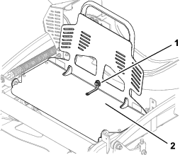
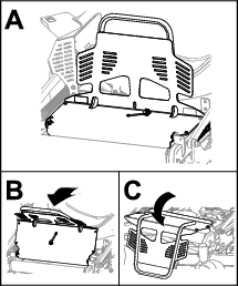
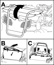
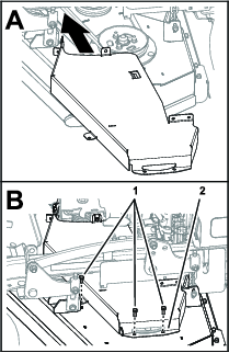
Opening the Engine Guard and Removing the Guard Extension
Opening the Engine Guard
Disconnecting the Spark-Plug Wire
Remove the spark-plug wire from the spark plug.
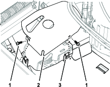
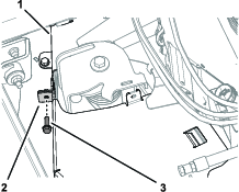
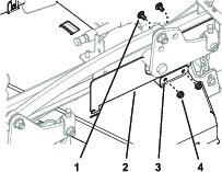
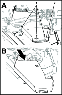
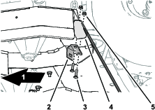
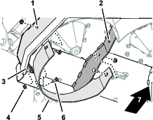
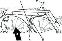
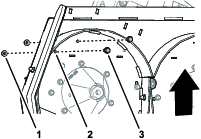
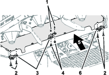
Removing the Left Belt Cover
-
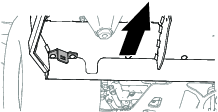
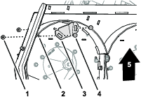
Remove the 2 flange-head screws that secure the tensioner cover to the left belt cover, and remove the tensioner cover (Figure 5).
-
Remove the bolt that secure the belt cover flanges as shown in Figure 6.
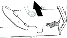
-
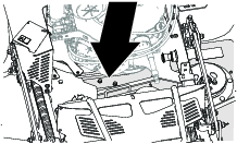
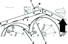
Remove the 2 carriage bolts and 2 locknuts that secure the left side CE cover to the left belt cover (Figure 7).
-
Remove the 3 bolts that secure the left belt cover to the deck, and remove the cover (Figure 8).
Removing the Existing Blades
-
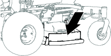
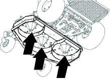
Lift the machine so that you can access the bottom of the mower deck.
-
Remove the existing blades from the spindles; refer to the Operator’s Manual for your machine.
Note: Save the blades for use when cutting grass in rear discharge mode.You will use the blade bolt and washer for installing the recycler blades in Installing the Recycler Blades.
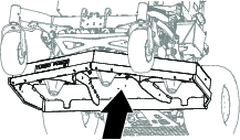
Drilling the Mower Deck
Drilling the Center Baffle Support Holes
-
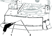
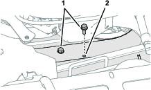
At the bottom of the mower deck, drill the 2 pilot holes in the deck with an 8 mm (5/16 inch) drill bit as shown in Figure 9.
-
Remove any burrs from the holes that you drilled.
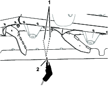
Drilling the Baffle and Kicker Fitting Holes
Note: Determine the left and right sides of the machine from the normal operating position.
-
At the left side of the mower deck, drill the pilot hole in the deck with a 10 mm (3/8 inch) drill bit as shown in Figure 10.
-
Remove any burrs from the holes.
-
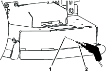
At the right side of the mower deck, drill the pilot hole in the deck with a 10 mm (3/8 inch) drill bit as shown in Figure 11.
-
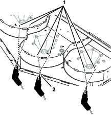
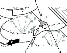
At the bottom of the mower deck, drill the 6 pilot holes in the deck with a 10 mm (3/8 inch) drill bit as shown in Figure 12.
-
At the left divider, drill the pilot hole in the divider with a 10 mm (3/8 inch) drill bit as shown in Figure 13.
-
Remove any burrs from the holes that you drilled.
Installing the Baffle Supports
Parts needed for this procedure:
| Left baffle support | 1 |
| Center/right baffle support | 2 |
| Flanged capscrew (5/16 x 3/4 inch) | 2 |
| Flange locknut (5/16 inch) | 6 |
| Carriage bolt (5/16 x 1-1/4 inches) | 4 |
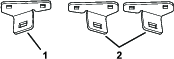
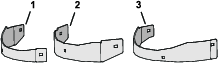
Identifying the Baffle Supports
Identify the left baffle support and the 2 center/right baffle supports (Figure 14).
Installing the Left Baffle Support
Note: Determine the left and right sides of the machine from the normal operating position.
-
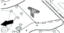
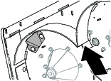
Remove the 2 outboard carriage bolts (5/16 x 7/8 inch) and 2 outboard flange locknuts (5/16 inch) that secure the deflector bracket to the mower deck (Figure 15).
-
Align the holes in the left baffle support with the holes on the mower deck and deflector bracket (Figure 16).
-
Assemble the left baffle support to the mower deck and deflector bracket (Figure 16) with 2 carriage bolts (5/16 x 1-1/4 inch) and 2 flange locknuts (5/16 inch).
-
Torque the 2 flange locknuts to 20 to 25 N∙m (15 to 18 ft-lb).
Installing the Right Baffle Support
Note: Determine the left and right sides of the machine from the normal operating position.
-
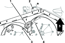
Remove the 2 outboard carriage bolts (5/16 x 7/8 inch) and 2 outboard flange locknuts (5/16 inch) that secure the deflector bracket to the mower deck (Figure 17).
-
Align the holes in the center/right baffle support with the holes on the mower deck and deflector bracket (Figure 18).
-
Assemble a center/right baffle support to the mower deck and deflector bracket (Figure 18) with 2 carriage bolts (5/16 x 1-1/4 inch) and 2 flange locknuts (5/16 inch).
-
Torque the 2 flange locknuts to 20 to 25 N∙m (15 to 18 ft-lb).
Installing the Center Baffle Support
Note: Determine the left and right sides of the machine from the normal operating position.
-
At the top of the mower deck, insert 2 flange-head bolts (5/16 x 3/4 inch) through the 8 mm (5/16 inch) holes that you drilled in Drilling the Center Baffle Support Holes.
-
At the bottom of the mower deck, assemble a center/right baffle support onto the flange-head bolts with 2 flange locknuts (5/16 inch).
-
Torque the 2 flange locknuts to 20 to 25 N∙m (15 to 18 ft-lb).
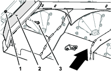
Installing the Baffles
Parts needed for this procedure:
| Baffle (right) | 1 |
| Baffle (center) | 1 |
| Baffle (left) | 1 |
| Carriage bolt (3/8 x 1 inch) | 9 |
| Flange locknut (3/8 inch) | 9 |
Identifying the Baffles
Identify the left, center, and right baffles (Figure 21).
Installing the Baffles
Note: Determine the left and right sides of the machine from the normal operating position.
-
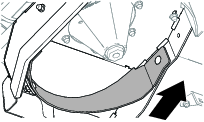
Align the holes in the right baffle with the hole in the right side plate of the mower deck, the hole in the center/right baffle support, and the hole in the right divider as shown in Figure 22.
-
Assemble the right baffle to the mower deck side plate, the baffle support, and the divider (Figure 22) with 3 carriage bolts (3/8 x 1 inch) and 3 flange locknuts (3/8 inch).
-
Align the holes in the center baffle with the hole in the right divider, the hole in the other center/right baffle support, and the left divider as shown in Figure 23.
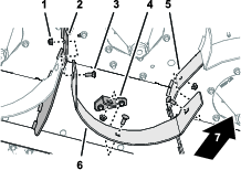
-
Assemble the center baffle to the right and left dividers (Figure 23) with 3 carriage bolts (3/8 x 1 inch) and 3 flange locknuts (3/8 inch).
-
Align the holes in the left baffle with the hole in the left side plate of the mower deck, the hole in the left baffle support, and the hole in the left divider as shown in Figure 24.
-
Assemble the left baffle to the mower deck side plate, the baffle support, and the divider (Figure 24) with 3 carriage bolts (3/8 x 1 inch) and 3 flange locknuts (3/8 inch).
-
Torque the 9 flange locknuts (3/8 inch) to 27 to 33 N∙m (37 to 45 ft-lb).
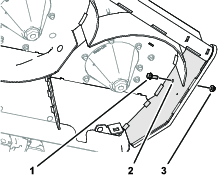
Installing the Kicker Fittings
Parts needed for this procedure:
| Kicker fitting | 3 |
| Carriage bolt (3/8 x 1 inch) | 6 |
| Flange locknut (3/8 inch) | 6 |
Note: Determine the left and right sides of the machine from the normal operating position.
-
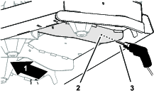
At the right side of the mower deck, align the slots in the kicker fitting with the 2 holes 10 mm (3/8 inch) that you drilled into the mower deck (Figure 25).
-
Assemble the kicker fitting to the deck (Figure 25) with 2 carriage bolts (3/8 x 1 inch) and 2 flange locknuts (3/8 inch).
-
At the middle of the mower deck, align the slots in the kicker fitting with the 2 holes 10 mm (3/8 inch) that you drilled into the mower deck (Figure 26).
-
Assemble the kicker fitting to the deck (Figure 26) with 2 carriage bolts (3/8 x 1 inch) and 2 flange locknuts (3/8 inch).
-
At the left side of the mower deck, align the slots in the kicker fitting with the 2 holes 10 mm (3/8 inch) that you drilled into the mower deck (Figure 27).
-
Assemble the kicker fitting to the deck (Figure 27) with 2 carriage bolts (3/8 x 1 inch) and 2 flange locknuts (3/8 inch).
-
Torque the 2 flange locknuts to 37 to 45 N∙m (27 to 33 ft-lb).
Installing the Recycler Blades
Parts needed for this procedure:
| Recycler blades (sold separately) | 3 |
Warning
A blade is sharp. Contact with a sharp blade can cause serious personal injury.
Wear gloves or wrap sharp edges of the blade with a rag.
Install the recycler blades onto the mower; refer to the Parts Catalog for your machine for the blade part number and the Operator’s Manual for your machine for installation instructions.
Installing the Left Belt Cover
-
Assemble the left belt cover to the deck (Figure 28) with the 3 bolts that you removed in Removing the Left Belt Cover.
-
Assemble the left side CE cover to the left belt cover (Figure 29) with the 2 carriage bolts and 2 locknuts that you removed in Removing the Left Belt Cover.
-
Secure the belt cover flanges with the flange-head screw (Figure 30) that you removed in Removing the Left Belt Cover.
-
Assemble the tensioner cover to the left belt cover with the 2 flange-head screws that you removed in Removing the Left Belt Cover, as shown in Figure 31.
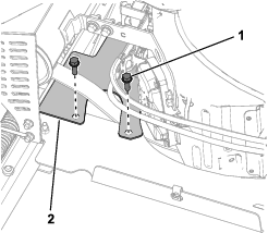
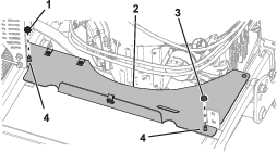
Installing the Guard Extension and Closing the Engine Guard
Installing the Guard Extension
Connecting the Spark-Plug Wire
Connect the spark-plug wire to the spark plug.
Converting the Mower Deck for Rear-Discharge Operation
Parts needed for this procedure:
| Flange-head capscrew (3/8 x 1 inch) | 8 |
Preparing to Remove the Mulching Kit
-
Prepare the mower; refer to Preparing the Mower.
-
Open the engine guard and remove the guard extension; refer to Opening the Engine Guard and Removing the Guard Extension.
-
Remove the belt cover; refer to Removing the Left Belt Cover.
-
Remove the recycling blades; refer to the Operator’s Manual for your machine.
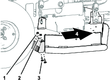
Removing the Kicker Fittings
Note: Determine the left and right sides of the machine from the normal operating position.
-
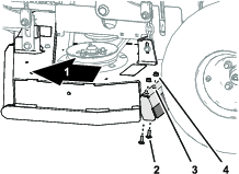
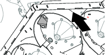
At the bottom left side of the mower deck, remove the 2 carriage bolts (3/8 x 1 inch) and 2 flange locknuts (3/8 inch) that secure the kicker fitting to the deck, and remove the kicker fitting (Figure 36).
-
At the bottom, center side of the mower deck, remove the 2 carriage bolts (3/8 x 1 inch) and 2 flange locknuts (3/8 inch) that secure the kicker fitting to the deck, and remove the kicker fitting (Figure 37).
-
Install 2 flange-head capscrews (3/8 x 1 inch) into the 10 mm (3/8 inch) holes in the mower deck (Figure 38) and secure the capscrews with 2 flange locknuts (3/8 inch) that you removed in step 2.
-
At the bottom, right side of the mower deck, remove the 2 carriage bolts (3/8 x 1 inch) and 2 flange locknuts (3/8 inch) that secure the kicker fitting to the deck, and remove the kicker fitting (Figure 39).
-
Install 2 flange-head capscrews (3/8 x 1 inch) into the 10 mm (3/8 inch) holes in the mower deck (Figure 39) and secure the capscrews with 2 flange locknuts (3/8 inch) that you removed in step 4.
Note: Retain the carriage bolts and kicker fitting for installation.
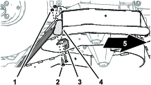
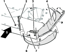
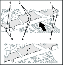
Removing the Baffles
Note: Determine the left and right sides of the machine from the normal operating position.
-
At the bottom, left side of the mower deck, remove the 3 carriage bolts (3/8 x 1 inch) and 3 flange locknuts (3/8) that secure the left baffle to the mower deck side plate, the left baffle support; and the left divider; and remove the left baffle (Figure 41).
-
Install a flange-head capscrew (3/8 x 1 inch) into the 10 mm (3/8 inch) holes in the mower deck (Figure 42) and secure the capscrews with the flange locknut (3/8 inch) that you removed in step 1.
-
At the bottom, center side of the mower deck, remove the 3 carriage bolts (3/8 x 1 inch) and 3 flange locknuts (3/8) that secure the center baffle to the left divider, center/right baffle support, and right divider; and remove the center baffle (Figure 43).
-
At the bottom, right side of the mower deck, remove the 3 carriage bolts (3/8 x 1 inch) and 3 flange locknuts (3/8) that secure the right baffle to the mower deck side plate, the center/right baffle support; and the right divider; and remove the right baffle (Figure 44).
-
Install a flange-head capscrew (3/8 x 1 inch) into the 10 mm (3/8 inch) holes in the mower deck (Figure 45) and secure the capscrews with the flange locknut (3/8 inch) that you removed in step 4.
Note: Retain the carriage bolts and baffles for installation.
Removing the Baffle Brackets
-
Remove the 2 flange locknuts (5/16 inch) that secure the left baffle support (Figure 46).
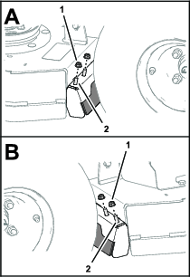
-
Remove the 2 flange locknuts (5/16 inch) that secure the right baffle support (Figure 46).
-
Remove the left baffle support and 2 carriage bolt (5/16 x 1-1/4 inch) from the bottom of the mower deck as shown in Figure 47.
-
Remove the right baffle support and 2 carriage bolt (5/16 x 1-1/4 inch) from the bottom of the mower deck as shown in Figure 47.
-
Remove the 2 flange locknut (5/16 inch) that secure the center baffle support to the 2 flange-head bolts (5/16 x 3/4 inch), and remove the center support (Figure 47).
Note: Do not remove the flange-head bolts.
-
Install the 4 carriage bolts (Figure 48) that you remove in steps 3 and 4 into the holes in the mower deck, and secure the carriage bolts with the 4 flange locknuts that you removed in steps 1 and 2.
-
Install the 2 flange locknut (Figure 48) that you removed in step 5 onto the 2 flange-head bolts (5/16 x 3/4 inch).
Note: Retain the 3 baffle supports for installation.
Finishing Converting the Mower Deck for Rear-Discharge Operation
-
Install the non-recycling blades; refer to the Operator’s Manual for your machine.
-
Install the left belt cover; refer to Installing the Left Belt Cover.
-
Install the guard extension; refer to Installing the Guard Extension and Closing the Engine Guard.
-
Connect the spark-plug wire to the spark plug.
-
Close the engine guard; refer to Installing the Guard Extension and Closing the Engine Guard.
Operation
Selecting the Proper Height of Cut
Remove approximately 2.5 cm (1 inch) or no more than 1/3 of the grass blade when cutting. In exceptionally lush and dense grass you may need to raise the height-of-cut setting or convert the mower deck for rear discharge operations.
Mowing in Extreme Conditions
Air is required to cut and recut grass clippings in the mower housing, so do not set the height-of-cut too low or fully surround the housing by uncut grass. Always try to keep the back of the mower deck free from uncut grass, allowing air to be drawn into the housing. When making an initial cut through the center of an uncut area, operate the machine slower and back the machine if the mower starts to clog.
Mowing at Correct Intervals
Grass grows at different rates at different times of the year. To maintain the same cutting height, mow more often in early spring. As the grass growth rate slows in midsummer, mow less frequently. If you cannot mow for an extended period, first mow at a high cutting height, then mow again 2 days later at a lower height setting.
Mowing with Sharp Blades
A sharp blade cuts cleanly and without tearing or shredding the grass. A dull blade tears and shreds the grass. Tearing and shredding causes the grass to turn brown at the edges, which impairs growth and increases susceptibility to disease.
Cleaning the Mower Deck
To ensure optimum performance, clean the underside of the mower deck after each use.
Important: Do not use brackish or reclaimed water to clean the machine.
Note: If residue grass builds up in the mower deck, cutting performance decreases.