


Maintenance
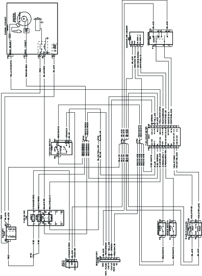
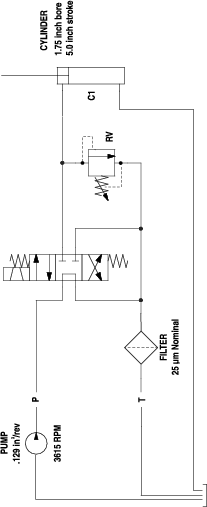
Download a free copy of the electrical or hydraulic schematic by visiting www.Toro.com and searching for your machine from the Manuals link on the home page.
Maintenance Safety Information
Warning
While maintenance or adjustments are being made, someone could start the engine. Accidental starting of the engine could seriously injure you or other bystanders.
Remove the key from the ignition switch, engage parking brake, and pull the wire(s) off the spark plug(s) before you do any maintenance. Also push the wire(s) aside so it does not accidentally contact the spark plug(s).
-
Park machine on level ground, raise the tines, set parking brake, stop engine, remove key or disconnect spark plug wire. Wait for all movement to stop and allow the machine to cool before adjusting, cleaning or repairing. Never allow untrained personnel to service machine.
Warning
The engine can become very hot. Touching a hot engine can cause severe burns.
Allow the engine to cool completely before service or making repairs around the engine area.
-
Disconnect battery or remove spark plug wire before making any repairs. Disconnect the negative terminal first and the positive last. Reconnect positive first and negative last.
-
Keep the machine, guards, shields and all safety devices in place and in safe working condition. Frequently check for worn or deteriorating components and replace them with the manufacturer’s recommended parts when necessary.
Warning
Removal or modification of original equipment, parts and/or accessories may alter the warranty, controllability, and safety of the machine. Unauthorized modifications to the original equipment or failure to use original Toro parts could lead to serious injury or death. Unauthorized changes to the machine, engine, fuel or venting system, may violate applicable safety standards such as: ANSI, OSHA and NFPA and/or government regulations such as EPA and CARB.
-
Use care when checking and servicing tines. Wrap the tine(s) or wear gloves, and use caution when servicing them. Only replace damaged tines. Never straighten or weld them.
-
Use jack stands to support the machine and/or components when required.
Caution
Raising the machine for service or maintenance relying solely on mechanical or hydraulic jacks could be dangerous. The mechanical or hydraulic jacks may not be enough support or may malfunction allowing the machine to fall, which could cause injury.
Do not rely solely on mechanical or hydraulic jacks for support. Use adequate jack stands or equivalent support.
-
Carefully release pressure from components with stored energy.
Warning
Hydraulic fluid escaping under pressure can penetrate skin and cause injury. Fluid accidentally injected into the skin must be surgically removed within a few hours by a doctor familiar with this form of injury or gangrene may result.
-
If equipped, make sure all hydraulic fluid hoses and lines are in good condition and all hydraulic connections and fittings are tight before applying pressure to hydraulic system.
-
Keep body and hands away from pinhole leaks or nozzles that eject high pressure hydraulic fluid.
-
Use cardboard or paper, not your hands, to find hydraulic leaks.
-
Before performing any work on the hydraulic system:
– Safely relieve all pressure in the ground drive hydraulic system by placing the motion control levers in neutral and shutting off the engine.
– Safely relieve all pressure in the auxiliary hydraulic system by shutting off the engine, turning the ignition switch to the “ON” position, and pressing the tine ground engagement switch. Once the tines have lowered to the ground, release the tine ground engagement switch and turn the ignition switch to the “OFF” position.
-
-
Keep hands and feet away from moving parts. If possible, Do Not make adjustments with the engine running. If the maintenance or adjustment procedure require the engine to be running and components moving, use extreme caution.
Warning
Contact with moving parts or hot surfaces may cause personal injury.
Keep your fingers, hands, and clothing clear of rotating components and hot surfaces.
-
Check all bolts frequently to maintain proper tightness.
Recommended Maintenance Schedule(s)
| Maintenance Service Interval | Maintenance Procedure |
|---|---|
| After the first 5 hours |
|
| After the first 100 hours |
|
| Before each use or daily |
|
| Every 25 hours |
|
| Every 50 hours |
|
| Every 80 hours |
|
| Every 100 hours |
|
| Every 160 hours |
|
| Every 200 hours |
|
| Every 250 hours |
|
| Every 300 hours |
|
| Monthly |
|
| Yearly |
|
| Yearly or before storage |
|
Pre-Maintenance Procedures
Caution
Raising the machine for service or maintenance relying solely on mechanical or hydraulic jacks could be dangerous. The mechanical or hydraulic jacks may not be enough support or may malfunction allowing the machine to fall, which could cause injury.
Do not rely solely on mechanical or hydraulic jacks for support. Use adequate jack stands or equivalent support.
Preparing for Maintenance
-
Park the machine on a level surface and engage the parking brake.
-
Shut off the engine, remove the key, and wait for all moving parts to stop.
-
Allow the engine to cool.
-
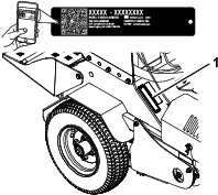
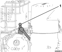
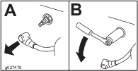
Disconnect the spark-plug wire from the spark plug and keep the wire away from the plug, to prevent accidental starting (Figure 30).
Lubrication
Lubricating the Chains
| Maintenance Service Interval | Maintenance Procedure |
|---|---|
| Before each use or daily |
|
Important: Do not lubricate the chains with penetrating oil or solvents. Use an oil or chain lubricant.
-
Shut off the engine, wait for all moving parts to stop, and remove the key. Engage the parking brake.
-
Lift the rear of the machine and support using jack stands or equivalent support.
Caution
Raising the machine for service or maintenance relying solely on mechanical or hydraulic jacks could be dangerous. The mechanical or hydraulic jacks may not be enough support or may malfunction allowing the machine to fall, which could cause injury.
Do not rely solely on mechanical or hydraulic jacks for support. Use adequate jack stands or equivalent support.
-
Start the engine and move throttle control ahead to 1/2 throttle position. Disengage the parking brake.
Warning
The engine must be running and the drive wheels must be turning so that adjustments can be performed. Contact with moving parts or hot surfaces may cause personal injury.
Keep your fingers, hands, and clothing clear of rotating components and hot surfaces.
-
With the engine running, slowly move the motion-control levers forward and lubricate all 4 chains.
-
Check the condition and tension of the chains; refer to Checking the Condition of the Chains.
Lubricating the Grease Fittings
| Maintenance Service Interval | Maintenance Procedure |
|---|---|
| Every 25 hours |
|
| Yearly |
|
Note: See the chart below for service intervals.
-
Shut off the engine, wait for all moving parts to stop, and remove the key. Engage the parking brake.
-
Lubricate the fittings with NLGI grade No. 2 multi-purpose grease.
Refer to the following chart for fitting locations and lubrication schedule.
Lubrication Chart
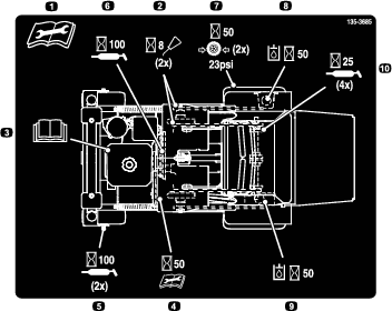
Fitting Locations Initial Pumps Number of Places Service Interval 1. Front Wheel Caster Hubs 1 2 Yearly 2. Tine Shaft Bearings 1 4 25 hours 3. Belt Idler Pivot 1 1 Yearly 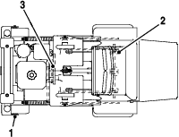
Engine Maintenance
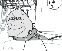
Servicing the Air Cleaner
| Maintenance Service Interval | Maintenance Procedure |
|---|---|
| Every 50 hours |
|
| Every 200 hours |
|
| Every 300 hours |
|
Important: Do not operate the engine without the air filter assembly; extreme engine damage may occur.
-
Release the latches on the cover for the air cleaner.
-
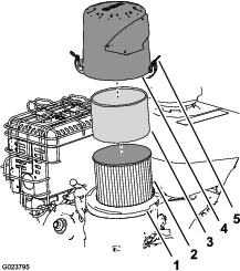
Remove the cover and clean it thoroughly ().
Note: Be careful to prevent dirt and debris from falling into the base.
-
Remove the foam pre-cleaner, wash it with a mild detergent and water, and then blot it dry (Figure 32).
-
Remove and inspect the paper air filter (); discard it if it is excessively dirty.
Important: Do not try to clean a paper filter.
-
Wipe dirt away from the base and the cover with a moist rag.
Note: Be careful to prevent dirt and debris from entering the air duct leading to the carburetor.
-
Install the foam pre-cleaner onto the paper air filter (Figure 32).
Note: Use a new paper air filter if you discarded the old one.
-
Install the air filter assembly to the air-filter base (Figure 32).
-
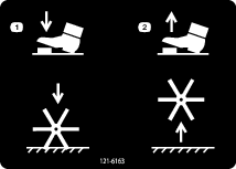
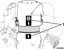
Align the arrow decal on the air-cleaner cover and the arrow decal on the base (Figure 33).
-
Secure the air-filter cover to the base with the latches.
Servicing the Engine Oil
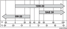
Engine-Oil Specifications
Oil Type: Detergent oil (API service SJ or later)
Engine Oil Capacity: 1.7 L (1.8 US qt) without the filter; 1.5 L (1.6 US qt) with the filter.
Oil viscosity: Refer to the table below.
Checking the Engine-Oil Level
| Maintenance Service Interval | Maintenance Procedure |
|---|---|
| Before each use or daily |
|
Important: Do not operate the engine with the oil level below the Low (or Add) mark on the dipstick, or over the Full mark.
-
Move the machine to a level surface.
-
Shut off the engine, engage the parking brake, remove the key, and wait for all moving parts to stop before leaving the operating position.
-
Allow the engine to cool.
-
Check the engine-oil level as shown in Figure 35.
-
If the oil level is low, wipe off the area around the oil fill cap, remove cap and add the specified oil until the oil level is at the Full mark on the dipstick.
Note: Do not overfill the engine with oil.
Changing the Engine Oil
| Maintenance Service Interval | Maintenance Procedure |
|---|---|
| After the first 5 hours |
|
| Every 100 hours |
|
Note: Dispose of the used oil at a recycling center.
-
Park the machine so that the drain side is slightly lower than the opposite side to assure the oil drains completely.
-
Shut off the engine, engage the parking brake, remove the key, and wait for all moving parts to stop before leaving the operating position.
-
Change the engine oil as shown in Figure 36.
Note: Torque drain plug to 18 N∙m (13 ft-lb).
-
Slowly pour approximately 80% of the specified oil into the filler tube, and slowly add the additional oil to bring it to the Full mark (Figure 37).
-
Start the engine and drive to a flat area.
-
Check the engine-oil level.
-
Reset the engine-oil service reminder; refer to Resetting the Engine-Oil Maintenance Reminder.
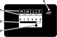
Resetting the Engine-Oil Maintenance Reminder
-
Prepare the machine for maintenance; refer to Preparing for Maintenance.
Note: You must engage the parking brake to reset the maintenance reminder.
-
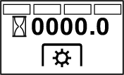
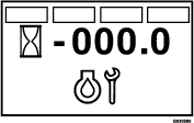
Cycle the key switch between the RUN position and the OFF position 4 times within 8 seconds.
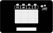
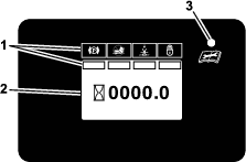
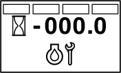
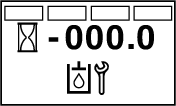
The Service Engine screen displays and flashes (Figure 38).
-
Press down the multi-function switch.
The engine-oil maintenance reminder resets to 100.0 (hours), exits the Service Engine screen, and returns to the default screen.
Note: You can exit the Service Engine screen at any time by turning the key to either the OFF or the START positions.
Servicing the Spark Plug
| Maintenance Service Interval | Maintenance Procedure |
|---|---|
| Every 160 hours |
|
Type for all Engines: NGK BR6HS, Champion RTL86C, or equivalent
Air Gap: 0.76 mm (0.030 inch)
Ensure that the air gap between the center and side electrodes is correct before installing the spark plug.
Use a spark plug wrench for removing and installing the spark plug(s) and a gapping tool/feeler gauge to check and adjust the air gap. Install a new spark plug(s) if necessary.
Removing the Spark Plug
-
Shut off the engine, engage the parking brake, remove the key, and wait for all moving parts to stop before leaving the operating position.
-
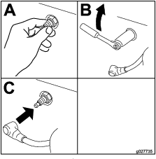
Remove the spark plug as shown in Figure 39.
Checking the Spark Plug
Important: Do not clean the spark plug(s). Always replace the spark plug(s) when it has a black coating, worn electrodes, an oily film, or cracks.
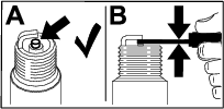
If you see light brown or gray on the insulator, the engine is operating properly. A black coating on the insulator usually means the air cleaner is dirty.
Set the gap to 0.75 mm (0.03 inch).
Installing the Spark Plug
Tighten the spark plug(s) to 22 N∙m (16 ft-lb).
Checking the Spark Arrester
| Maintenance Service Interval | Maintenance Procedure |
|---|---|
| Every 50 hours |
|
Warning
Hot exhaust system components may ignite fuel vapors even after the engine is shut off. Hot particles exhausted during engine operation may ignite flammable materials. Fire may result in personal injury or property damage.
Do not refuel or run engine unless a spark arrester is installed.
-
Shut off the engine, engage the parking brake, remove the key, and wait for all moving parts to stop before leaving the operating position.
-
Allow the muffler to cool.
-
Check the spark arrester for breaks in the screen or welds.
Note: Replace the spark arrester if it is worn or damaged.
-
If you see that the screen is plugged, perform the following:
-
Remove the spark arrester.
-
Shake loose the particles from the arrester and clean screen with a wire brush.
Note: Soak the arrester screen in solvent if necessary.
-
Install spark arrester onto exhaust outlet.
-
Electrical System Maintenance
Checking the Safety Interlock
| Maintenance Service Interval | Maintenance Procedure |
|---|---|
| Before each use or daily |
|
Important: Ensure that the operator safety mechanisms are connected and are fully function prior to use.
Note: If the machine does not pass either of the tests that follow, Do not operate the machine. Contact your authorized Toro distributor.
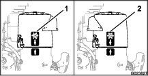
Checking the Engine Starting Circuit
Note: The state of the parking brake interlock you are checking is shown in bold.
| Engage the parking brake | The starter rotates |
 |  |
Check Parking Brake Interlock
Note: The state of the parking brake interlock you are checking is shown in bold.
| Disengage the parking brake | The starter should not rotate |
 |  |
Jump Starting a Discharged Battery
The following instructions are adapted from the SAE J1494 Rev. Dec. 2001 – Battery Booster Cables – Surface Vehicle Recommended Practice (SAE – Society of Automotive Engineers).
Danger
Jump starting a weak battery that is cracked, frozen, has low electrolyte level, or an open/shorted battery cell, can cause an explosion resulting in serious personal injury.
Do not jump start a weak battery if these conditions exist.
Warning
Batteries contain acid and produce explosive gases.
-
Always shield your eyes and face from the battery.
-
Do not lean over the batteries.
Preparing to Jump Start the Battery
Caution
Corrosion or loose connections can cause unwanted electrical voltage spikes at any time during the jump starting procedure.
Do Not attempt to jump start with loose or corroded battery terminals or damage to the engine may occur.
-
Check the cable clamps and battery terminals of the discharged battery for corrosion (white, green, or blue “snow”) and check that the hardware for the clamps is tight.
Clean corrosion from the battery terminals and cable clamps.
-
Check that the hardware for the cable clamps is tight.
Tighten the cable-clamp hardware as needed.
-
Check that the vent caps on the discharged battery and booster battery are tight and level.
-
If available, place damp clothes over the vent caps of both batteries.
-
If you are jump starting from the battery in another vehicle, ensure that it has a 12 V lead acid battery.
Important: Ensure that the 2 vehicles do not touch.
-
Ensure that the booster battery is fully charged with 12.6 V or greater.
-
Select properly sized jumper cables (4 to 6 AWG) with short lengths to reduce voltage drop between systems.
Choose jumper cables with color coded or polarity labeled cables or clamps.
Connecting the Jumper Cables
Caution
Connecting the jumper cables incorrectly (wrong polarity) can immediately damage the electrical system.
Be certain of battery terminal polarity and jumper cable polarity when hooking up batteries.
-
Connect the positive jumper cable—red (+) to the positive-battery terminal of the discharged battery as shown in Figure 42.
Note: The positive-battery terminal is wired to the starter or solenoid.
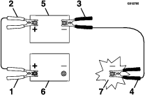
-
Connect the other end of the positive cable to the positive-battery terminal of the booster battery (Figure 42).
-
Connect the negative jumper cable—black (–) to the negative-battery terminal of the booster battery.
-
At the machine with a discharged battery, connect the other end of the negative jumper cable to the engine block, at a location away from the battery and belts (Figure 42).
Starting the Engine and Removing the Jumper Cables
Servicing the Battery
Danger
Charging or jump-starting the battery may produce explosive gases. Battery gases can explode, causing serious injury.
-
Keep sparks, flames, or cigarettes away from the battery.
-
Ventilate when charging or using the battery in an enclosed space.
-
Ensure that the venting path of the battery is always open once the battery is filled with acid.
-
Always shield your eyes and face from the battery.
Danger
Battery electrolyte contains sulfuric acid, which is fatal if consumed and can cause severe burns.
-
Wear safety glasses to shield your eyes and rubber gloves to protect your skin and clothing when handling electrolyte.
-
Do not swallow electrolyte.
-
In the event of an accident, flush with water and call a doctor immediately.
Caution
If the key switch is in the ON position, there is potential for sparks and engagement of components. Sparks could cause an explosion or moving parts could accidentally engage, causing personal injury.
Ensure that the key switch is in the OFF position before charging the battery.
Allowing batteries to stand for an extended period of time without recharging them results in reduced performance and service life. To preserve optimum battery performance and life, charge batteries in storage when the open circuit voltage drops to 12.4 V.
Note: To prevent damage due to freezing, the battery should be fully charged before putting away for winter storage.
Note: The machine is shipped with a filled, lead-acid battery.
Charging the Battery
| Maintenance Service Interval | Maintenance Procedure |
|---|---|
| Monthly |
|
-
Move the key switch to the OFF position and remove the key.
-
Measure the voltage of the battery with a voltmeter.
-
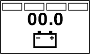
Use the table below to locate the charge state or the battery, and if needed, the battery-charger setting and charging interval recommended to charge the battery to 12.6 V or greater; refer to the battery charge table below.
Important: Ensure that the negative battery cable is disconnected and the battery charger used for charging the battery has an output of 16 V and 7 A or less to avoid damaging the battery (see chart for recommended charger settings).
Battery Charge Table
Voltage Reading Percent Charge Maximum Charger Settings Charging Interval 12.6 or greater 100% 16 V/ No charging required 7 A 12.4 to 12.6 75 to 100% 16 V/ 30 minutes 7 A 12.2 to 12.4 50 to 75% 16 V/ 1 hour 7 A 12.0 to 12.2 25 to 50% 14.4 V/ 2 hours 4 A 11.7 to 12.0 0 to 25% 14.4 V/ 3 hours 4 A 11.7 or less 0% 14.4 V/ 6 hours or more 2 A -
If the positive cable is also disconnected, connect the positive (red) cable to the positive battery terminal and slip the terminal cover over the positive terminal.
-
Remove the screw, washer, and ground cable from the engine. Connect the negative battery cable.
Note: If time does not permit charging the battery or if charging equipment is not available, connect the negative battery cables and run the vehicle continuously for 20 to 30 minutes to charge the battery.
Drive System Maintenance
Checking the Drive Tire Air Pressure
| Maintenance Service Interval | Maintenance Procedure |
|---|---|
| Every 50 hours |
|
Note: You do not adjust air pressure for the semi-pneumatic caster tires.
-
Shut off the engine, engage the parking brake, remove the key, and wait for all moving parts to stop before leaving the operating position.
-
Check the air pressure of the drive tires.
-
Adjust the air pressure in the drive tires to 152 to 165 kPa (22 to 24 psi).
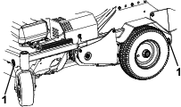
Checking the Wheel Hub Bolts
| Maintenance Service Interval | Maintenance Procedure |
|---|---|
| Yearly |
|
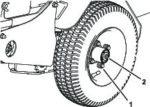
Torque the wheel hub bolts (Figure 43) to 37 to 45 N∙m (27 to 33 ft-lb).
Note: Do not use anti-seize compound on the wheel hub.
Checking the Torque of the Wheel Lug Nuts
| Maintenance Service Interval | Maintenance Procedure |
|---|---|
| Yearly |
|
Torque the wheel lug nuts (Figure 43) to 115 to 142 N∙m (85 to 105 ft-lb).
Checking the Condition of the Chains
| Maintenance Service Interval | Maintenance Procedure |
|---|---|
| Before each use or daily |
|
-
Shut off the engine, engage the parking brake, wait for all moving parts to stop, and remove the key.
-
Check the chains on both sides of the machine for proper tension. The chains should be able to move up and down 6 to 12 mm (1/4 to 1/2 inch).
-
If chains pop or snap refer to Adjusting the Drive Wheel Chain Tension and Adjusting the Tine Drive Chain.
Checking the Sprocket Condition
| Maintenance Service Interval | Maintenance Procedure |
|---|---|
| Before each use or daily |
|
-
Shut off the engine, engage the parking brake, wait for all moving parts to stop, and remove the key.
-
Inspect sprockets for wear and replace as required.
Maintaining the Chain
Adjusting the Drive Wheel Chain Tension
-
Shut off the engine, engage the parking brake, wait for all moving parts to stop, and remove the key.
-
Lift the rear of the machine and support using jack stands or equivalent support.
-
Check the chains on each side of the idler sprocket, at both sides of the machine, for proper tension.
The chains should move up and down 6 to 12 mm (1/4 to 1/2 inch).
-
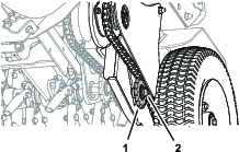
To adjust the chain tension, loosen the idler bolt and locknut, and push up on the sprocket to tighten the chain (Figure 44).
Important: Do not overtighten the chain. Significant chain wear can occur and will shorten the life of an overtightened chain.
-
Check the chain tension and tighten the idler bolt and locknut.
Checking the Torque of the Transmission Output Shaft Nut
| Maintenance Service Interval | Maintenance Procedure |
|---|---|
| After the first 5 hours |
|
| Yearly |
|
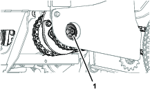
Torque the nuts (Figure 45) on the transmission output tapered shafts to 285 to 353 N∙m (210 to 260 ft-lb).
Adjusting the Motion Control Linkage
-
Refer to Preparing for Maintenance.
-
Push the control levers all the way forward to the front reference bar; If either of the control levers contact the reference bar do the following:
-
Allow the control levers to return to neutral and loosen the 2 jam nuts on the hex adjustment linkage (Figure 46).
Note: One jam nut is a right-hand thread and the other is left-hand.
-
Turn the hex adjustment linkage until there is 3 to 6 mm (1/8 to 1/4 inch) gap between the control lever and the front reference bar.
-
Tighten the jam nuts (Figure 46).
-
-
Allow the control levers to return to neutral. Turn the left hex adjustment link until the motion control levers are approximately even with each other.
-
Repeat steps 2 and 3 for the other motion control linkage.
Adjusting the Motion Control Tracking
If the machine travels or pulls to one side when the motion control levers are in the full forward position, adjust the tracking.
-
Push both control levers forward the same distance.
-
Check if the machine pulls to one side; If it does, stop the machine and set the parking brake.
-
Loosen the lock nuts on the right motion control linkage (as viewed from the rear of the machine. Push the right control lever forward and rotate the adjustment rod until there is 1/8 to 1/4 inch (3 to 6 mm) gap between the right control lever and the front reference bar.
-
Place the front reference/speed control bar in the maximum forward position; refer to Adjusting the Front Reference/Speed Control Bar.
-
Rotate the adjustment rod on the left side of the machine (Figure 47).
-
Looking down towards the adjustment rod — rotate it counterclockwise, in 1/4 turn increments, to increase speed or clockwise to decrease speed.
-
Drive the machine and check the full forward tracking.
-
Repeat steps 5 through 7 until desired tracking is obtained.
Check Transmission Mount Bolt Torque
| Maintenance Service Interval | Maintenance Procedure |
|---|---|
| After the first 5 hours |
|
| Yearly |
|
Torque the 4 transmission bolts to 56-69 N-m (41-51 ft-lb); refer to Figure 48.
Note: Do Not use anti-seize compound on the wheel hub.
Brake Maintenance
Adjusting the Parking Brake
If the parking brake does not hold securely, an adjustment is required.
-
Refer to Preparing for Maintenance.
-
Check the air pressure in the drive tires. If needed, adjust to the recommended inflation; refer to Checking the Drive Tire Air Pressure.
-
Disengage the parking brake.
-
Loosen the cable clamp on the brake cables under the console (Figure 49).
-
Adjust both cable conduits downward approximately 3 to 6 mm (1/8 to 1/4 inch).
-
Tighten the cable clamp and engage the parking brake.
-
Check the parking brake; repeat steps 4 through 6 if necessary.
Belt Maintenance
Checking the Condition and Tension of the Belts
| Maintenance Service Interval | Maintenance Procedure |
|---|---|
| Every 50 hours |
|
-
Shut off the engine, engage the parking brake, wait for all moving parts to stop, and remove the key.
-
Check the auxiliary pump drive belt condition and tension; the belt should be snug. Refer to Adjusting the Auxiliary Pump Drive Belt.
-
Check the condition of the transmission drive belt.
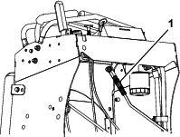
Adjusting the Auxiliary Pump Drive Belt
-
Shut off the engine, engage the parking brake, wait for all moving parts to stop, and remove the key.
-
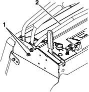
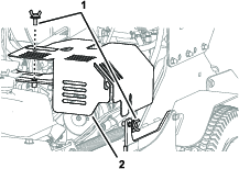
Remove the top thumbscrew, loosen the side thumbscrew, and remove the left hydraulic compartment cover (Figure 50).
-
Loosen the 2 flange locknuts (3/8 inch) securing the auxiliary pump to the mounting bracket (Figure 51).
-
Slide the pump outward (Figure 51) in slots and torque the flange locknuts to 37 to 45 N∙m (27 to 33 ft lb).
When properly adjusted, the belt should have 1.3 cm (1/2 inch) of deflection with 3 pounds of force on the belt midway between the auxiliary pump and engine pulley.
-
Align the hole and slot in the left hydraulic compartment cover with the supports of the machine and secure the cover with the 2 thumbscrews (Figure 50).
Checking the Transmission Drive Belt Tension
Note: No adjustments are required for belt tension.
-
Shut off the engine, engage the parking brake, wait for all moving parts to stop, and remove the key.
-
Install the new belt.
-
Ensure that the idler arm and pulley can move freely.
Hydraulic System Maintenance
Auxiliary Hydraulic Fluid Specification
Hydraulic fluid type: AW-32 hydro fluid
Checking the Auxiliary Hydraulic Fluid Level
Note: The machine is shipped with hydraulic fluid in the reservoir.
-
Run the machine for approximately 15 minutes to purge any extra air out of the hydraulic system.
-
Completely raise and lower the tines 3 times to purge the air.
-
Shut off the engine, remove the key and allow the machine to cool.
-
Remove the cap and check the hydraulic-fluid level in the reservoir.
Note: The hydraulic-fluid level should cover the word FULL COLD that is embossed into the baffle of the reservoir (Figure 52).
-
If necessary, add the specified hydraulic fluid to the reservoir until the fluid covers the FULL COLD fluid level on the baffle (Figure 52).
Note: If the fluid is at ambient-air temperature, about 24°C (75° F), fill only to the FULL COLD level.
-
Install the hydraulic reservoir cap (Figure 52) and tighten it until snug.
Note: Do not overtighten the reservoir cap.
Changing the Auxiliary Hydraulic Reservoir Fluid and Filter
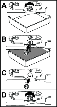
Draining the Auxiliary Hydraulic Fluid
-
Run the machine for approximately 15 minutes to purge any extra air out of the hydraulic system.
-
Completely raise and lower the tines 3 times to purge the air.
-
Shut off the engine, engage the parking brake, wait for all moving parts to stop, and remove the key.
-
Allow the engine to cool.
-
Carefully clean the area around the front of the auxiliary pump and fill cap; also clean around the filter. It is important that no dirt or contamination enter hydraulic system.
-
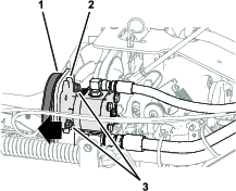
Loosen the suction hose at the pump fitting, clean around the pump fitting, and allow oil to drain (Figure 53).
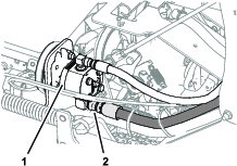
-
Install the suction hose and torque to 50 N-m (37 ft-lb).
Changing the Filter
| Maintenance Service Interval | Maintenance Procedure |
|---|---|
| After the first 100 hours |
|
| Every 250 hours |
|
-
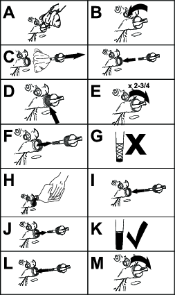
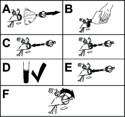
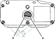
Unscrew the filter to remove it and allow oil to drain (Figure 54).
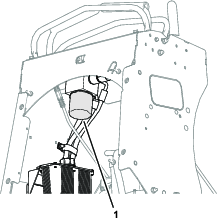
-
Apply a thin coat of the specified hydraulic fluid to the rubber seal of the new filter; refer to Auxiliary Hydraulic Fluid Specification.
-
Turn the filter clockwise until rubber seal contacts the filter adapter, then tighten the filter an additional 2/3 to 3/4 turn (Figure 54).
Adding Auxiliary Hydraulic Fluid
-
Remove the cap and check the hydraulic-fluid level in the reservoir.
-
Add the specified hydraulic fluid until the level reaches the FULL COLD line located on the reservoir tank; refer to Auxiliary Hydraulic Fluid Specification and Checking the Auxiliary Hydraulic Fluid Level.
Note: If the fluid is at ambient-air temperature, about 24°C (75° F), fill only to the FULL COLD level.
-
Install the hydraulic reservoir cap and tighten it until snug.
Note: Do not overtighten the reservoir cap.
-
Start the engine and raise and lower the tines. Lower the tines to the ground and refill the reservoir to the FULL COLD line.
-
Check the fluid level again; repeat steps 2 through 5 until the level does not decrease.
Transmission Fluid Specification
Transmission fluid type: Toro® Hypr-Oil™ 500 or Mobil® 1 15W-50 synthetic motor oil.
Important: Use the specified fluid. Other fluids could cause system damage.
Checking the Transmission Fluid Level
| Maintenance Service Interval | Maintenance Procedure |
|---|---|
| Every 50 hours |
|
-
Shut off the engine, engage the parking brake, remove the key, and wait for all moving parts to stop before leaving the operating position.
-
Allow the machine to cool.
-
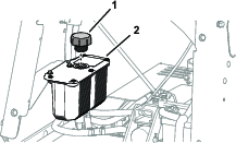
Remove the cap from the expansion tank and check the transmission-fluid level in the tank (Figure 55).
Note: The transmission fluid level should cover the FULL COLD fill line molded into the side of the tank.
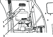
-
If necessary, add the specified transmission fluid until the fluid level is at the FULL COLD fill line of the expansion tank (Figure 55).
-
Install the expansion tank cap and tighten it until snug.
Important: Do not overtighten the expansion tank cap.
Changing the Hydraulic Transmission Filters and Fluid
| Maintenance Service Interval | Maintenance Procedure |
|---|---|
| After the first 100 hours |
|
| Every 250 hours |
|
Important: Do not change the hydraulic fluid (except for what can be drained when changing filter and removing the drain plugs), unless it is felt the oil has been contaminated or been extremely hot.Changing the oil unnecessarily could damage hydraulic system by introducing contaminants into the system.
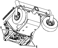
Draining the Auxiliary Hydraulic Fluid
-
Shut off the engine, engage the parking brake, wait for all moving parts to stop, and remove the key.
-
Place a drain pan between the transmissions.
-
Remove the 2 drain plugs, located at the bottom of each transmission, and allow the fluid to drain.
-
Locate the 2 filters under the transmissions (Figure 56).
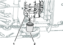
-
Carefully clean area around filters.
Important: Do not allow dirt or contaminants to enter the hydraulic system.
-
Remove the filters to and allow the fluid to drain from the drive system (Figure 56).
-
Install the 2 drain plugs.
Installing the Transmission Filters
-
Apply a thin coat of the specified hydraulic fluid to the rubber seal of the new filters; refer to Transmission Fluid Specification.
-
Turn the filter clockwise until rubber seal contacts the filter adapter, then tighten the filter an additional 2/3 to 3/4 turn (Figure 56).
-
Remove the vent plug at each transmission.
Adding Transmission Fluid
-
Remove cap from the expansion tank, add the specified transmission fluid to the tank until fluid comes out of the transmission vent, and install the plug; refer to Transmission Fluid Specification and Checking the Transmission Fluid Level.
-
Repeat step 1 until fluid comes out of the vent of the other transmission, and install the plug.
-
Torque the vent plugs to 180 in-lb (20 N·m).
-
Continue to adding the specified transmission fluid until it reaches the FULL COLD line on the expansion reservoir; refer to Figure 55 in Checking the Transmission Fluid Level.
-
Raise the rear of machine up and support with jack stands (or equivalent support) just high enough to allow the drive wheels to turn freely.
Caution
Raising the machine for service or maintenance relying solely on mechanical or hydraulic jacks could be dangerous. The mechanical or hydraulic jacks may not be enough support or may malfunction allowing the machine to fall, which could cause injury.
Do not rely solely on mechanical or hydraulic jacks for support. Use adequate jack stands or equivalent support.
-
Start the engine and move the throttle control ahead to 1/2 throttle position. Disengage the parking brake.
Warning
The engine must be running and the drive wheels must be turning so motion control adjustment can be performed. Contact with moving parts or hot surfaces may cause personal injury.
Keep your fingers, hands, and clothing clear of rotating components and hot surfaces.
-
With the engine running, slowly move the directional control in both forward and reverse directions (5 to 6 times). Check the oil level, and add oil as required after shutting off the engine.
It may be necessary to repeat step 7 until all air is purged from the system. Air is purged from the transaxle when it operates at normal sound levels and moves forward and reverse smoothly at normal speeds.
-
Shut off the engine, remove the key, engage the parking brake, and wait for all moving part to stop.
-
Remove the jack stands and lower the rear of machine.
-
Reset the transmission-oil maintenance reminder; refer to Resetting the Transmission-Oil Maintenance Reminder.
Resetting the Transmission-Oil Maintenance Reminder
-
Prepare the machine for maintenance; refer toPreparing for Maintenance.
Note: You must engage the parking brake to reset the maintenance reminder.
-
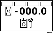
Cycle the key switch between the RUN position and the OFF position 6 times within 8 seconds.
The Service Transmission screen displays and flashes (Figure 57).
-
Press down the multi-function switch.
The transmission-oil maintenance reminder resets to 250 (hours), exits the service transmission screen, and returns to the default screen.
Note: You can exit the service transmission screen at any time by turning the key to either the OFF or the START positions.
Operator Weight Adjustment
Weight Adjustment Overview
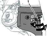
The operator weight adjustment valve is located at the left side of the control console (Figure 58).
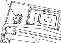
Use the operator weight adjustment valve to help compensate for the weight of the operator so that the machine achieves the correct aerating pressure, plug length, and to help maximize lateral machine stability; refer to the following procedures:
Important: Adjust the operator weight adjustment valve if the weight of each operator differs.
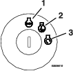
Assembling the Weight Control Knob
-
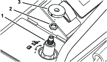
Ensure that the setscrew in the weight control knob is rotated counterclockwise enough so that the knob slips over the shaft of the weight control valve (Figure 59).
-
Ensure that the jam nut on the shaft of the weight control valve is tightened (Figure 59); refer to step 6 in Adjusting the Operator Weight Control Valve.
-
Assemble the knob onto the shaft of the weight control valve (Figure 59).
-
Tighten the setscrew of the knob by hand.
Adjusting the Operator Weight Control Valve
Note: Adjust the system pressure so that the drive tires lightly touch the ground.
Important: Keep the drive tires on the ground at all times to maximize lateral machine stability.
-
Raise the tines, drive the aerator to a hard, flat turf surface, and stop the aerator, but leave the engine running.
-
Have the operator stand on the operator’s platform.
-
Loosen the jam nut for the weight control valve, refer to Figure 59 in Assembling the Weight Control Knob.
-
Press the tine ground engagement foot switch to lower the tines.
-
If the machine raises and the ground tires are no longer touching, rotate the operator weight adjustment control counterclockwise to lower the machine until the tires touch the ground.
-
If the tines are not touching the ground, rotate the operator weight adjustment control clockwise until the tines lower and touch the ground (but not raise the machine).
Important: Keep the drive tires on the ground at all times to maximize lateral machine stability.
-
-
Release the tine ground engagement foot switch to raise the tines.
-
While holding the position of the knob for the weight control valve, tighten the jam nut.
Note: If you are having difficulty maintain the valve adjustment while tightening the jam nut, use a hex key in the shaft of the weight control valve.
Removing the Weight Control Knob
-
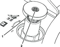
Loosen the setscrew in the knob for the weight control valve; refer to Figure 60 in Adjusting the Operator Weight Control Valve.
-
Lift the knob straight from the shaft.
Note: Do not twist the knob while removing it. If you need help maintaining the position of the control-valve shaft, use a hex key in the hex socket of the shaft to hold the align; refer to Figure 60 in Adjusting the Operator Weight Control Valve.
-
If the setscrew of the knob raised a burr on the shaft of the weight control valve, carefully remove the burr.
-
Store the knob for future adjustments.
Tine Maintenance
Checking the Tines
| Maintenance Service Interval | Maintenance Procedure |
|---|---|
| Before each use or daily |
|
-
Shut off the engine, engage the parking brake, remove the key, and wait for all moving parts to stop before leaving the operating position.
-
Raise the machine and support it with jack stands with a 460 kg (1,015 lb) capacity.
Caution
Raising the machine for service or maintenance relying solely on mechanical or hydraulic jacks could be dangerous. The mechanical or hydraulic jacks may not be enough support or may malfunction allowing the machine to fall, which could cause injury.
Do not rely solely on mechanical or hydraulic jacks for support. Use adequate jack stands or equivalent support.
-
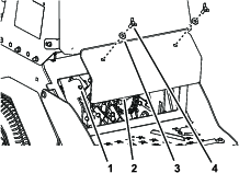
Remove the 2 thumbscrews (3/8 x 1 inch) and 2 washers (3/8 inch) that secure the rear-cover panel to the chassis, and remove the panel (Figure 61).
-
Remove rocks and other debris from the tines.
-
Inspect the tines for wear and damage.
Note: Replace any tines that are worn or damaged.
-
Align the holes in the rear-cover panel to the holes in the chassis (Figure 61).
-
Secure the cover panel to the chassis with the 2 thumbscrews and 2 washers (Figure 61) that you removed in step 3, and torque the bolts to 37 to 45 N∙m (27 to 33 in-lb)
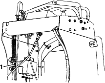
Adjusting the Tine Drive Chain
-
Shut off the engine, engage the parking brake, wait for all moving parts to stop, and remove the key.
-
Lift the rear of the machine and support using jack stands or equivalent support.
-
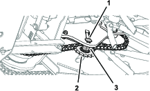
Check the chains on each side of the idler sprocket, at both sides of the machine, for proper tension.).
The chains should move up and down 6 to 12 mm (1/4 to 1/2 inch).
-
To adjust the chain tension, loosen the idler bolt and threaded spacer, and push up on the sprocket to tighten the chain (Figure 62).
Important: Do not overtighten the chain. Significant chain wear can occur and will shorten the life of an overtightened chain.
-
Check the chain tension and tighten the idler bolt.
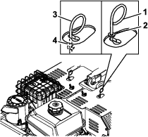
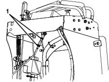
Adjusting the Return-to-Up Spring
Warning
Springs have stored energy. Overtightening the springs may cause the springs to fail which can cause serious injury or death and damage to the machine and property.
Make sure that the return-to-up springs are adjusted and/or replaced as instructed in this procedure.
Check the gap between the spring bracket and the end of the spring as shown in Figure 63. The gap should measure 35 mm (1.38 inch). The adjustment is made by turning the bolt at the front of each spring (clockwise will shorten the gap, counter-clockwise will lengthen the gap).
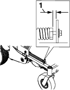
Important: The springs must be replaced it the gap is less than 29 mm (1.13 inches). Always replace both return-to-up springs. This prevents uneven loading and possible damage to the machine.
Chassis Maintenance
Check for Loose Hardware
| Maintenance Service Interval | Maintenance Procedure |
|---|---|
| Before each use or daily |
|
-
Engage parking brake, shut off the engine, remove the key, and wait for all moving parts to stop before leaving the operator’s position.
-
Inspect machine for any loose hardware or any other possible problem. Tighten hardware or correct the problem before operating.
Cleaning
Washing the Machine
Wash the machine as needed using water alone or with a mild detergent. You may use a rag when washing the machine.
Important: Do not use brackish or reclaimed water to clean the machine.
Important: Do not use power-washing equipment to wash the machine. Power-washing equipment may damage the electrical system, loosen important decals, or wash away necessary grease at friction points. Avoid excessive use of water near the control panel, engine, and battery.
Important: Do not wash the machine with the engine running. Washing the machine with the engine running may result in internal engine damage.
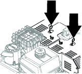
Cleaning the Engine and the Exhaust System Area
| Maintenance Service Interval | Maintenance Procedure |
|---|---|
| Before each use or daily |
|
Caution
Excessive debris around engine cooling air intake and exhaust system area can cause engine, exhaust area, and hydraulic system to overheat, which can create a fire hazard.
Clean all debris from engine and exhaust system area.
-
Shut off the engine, engage the parking brake, remove the key, and wait for all moving parts to stop before leaving the operating position.
-
Clean all debris from screen at the top of the engine, around engine shrouding, and exhaust system area.
-
Wipe up any excessive grease or oil around the engine and exhaust system area.
Removing the Engine Shrouds and Cleaning the Cooling Fins
| Maintenance Service Interval | Maintenance Procedure |
|---|---|
| Every 80 hours |
|
-
Shut off the engine, engage the parking brake, remove the key, and wait for all moving parts to stop before leaving the operating position.
-
Remove cooling shrouds from engine.
-
Clean cooling fins of the engine.
Note: Also clean dust, dirt, and oil from external surfaces of engine, which can cause improper cooling.
-
Install the cooling shrouds into the engine.
Important: Operating the engine without cooling shrouds causes engine damage due to overheating. Do not operate the machine without the cooling shrouds.
Cleaning the Debris from the Machine
| Maintenance Service Interval | Maintenance Procedure |
|---|---|
| Before each use or daily |
|
-
Shut off the engine, engage the parking brake, remove the key, and wait for all moving parts to stop before leaving the operating position.
-
Clean off any oil, debris, or grass buildup on the machine and aerator deck.
-
Clean off any debris or grass under the chain guards, around the fuel tank, and around the engine and exhaust area.
Disposing of Waste
Disposing of Waste Oil
Engine oil and hydraulic fluid are both pollutants to the environment. Dispose of used oil at a certified recycling center or according to your state and local regulations.
Disposing of the Battery
Danger
Battery electrolyte contains sulfuric acid, which is poisonous and can cause severe burns. Swallowing electrolyte can be fatal or if it touches skin can cause severe burns.
-
Wear safety glasses to shield eyes, and rubber gloves to protect skin and clothing when handling electrolyte.
-
Do not swallow electrolyte.
-
In the event of an accident, flush with water and call a doctor immediately.
Federal law states that batteries should not be placed in the garbage. Management and disposal practices for batteries must follow relevant federal, state, or local laws.
If a battery is being replaced or if the machine containing the battery is no longer operating and is being scrapped, remove the battery and take it to a local certified recycling center. If no local recycling is available return the battery to any certified battery reseller.