
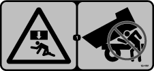
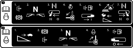
 , which means: Caution, Warning, or Danger—personal safety instruction. Failure to comply with the instruction
may result in personal injury or death.
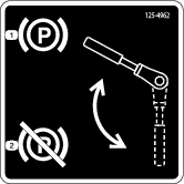
, which means: Caution, Warning, or Danger—personal safety instruction. Failure to comply with the instruction
may result in personal injury or death.


Maintenance
Note: Determine the left and right sides of the machine from the normal operating position.
Recommended Maintenance Schedule(s)
| Maintenance Service Interval | Maintenance Procedure |
|---|---|
| After the first 50 hours |
|
| Before each use or daily |
|
| Every 40 hours |
|
| Every 50 hours |
|
| Every 100 hours |
|
| Every 200 hours |
|
| Every 300 hours |
|
| Every 1,000 hours |
|
| Every 1,500 hours |
|
| Yearly |
|
| Yearly or before storage |
|
Important: Refer to your engine owner's manual for additional maintenance procedures.
Pre-Maintenance Procedures
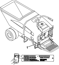
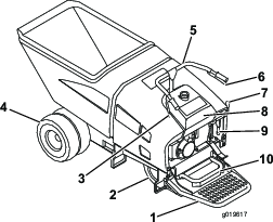
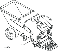
Removing the Cowl
Note: Dump the hopper before you remove the cowl by using either the hydraulics or by removing the pin in the hydraulic cylinder and the hopper base.
Lubrication
Greasing the Machine
| Maintenance Service Interval | Maintenance Procedure |
|---|---|
| Every 50 hours |
|
| Yearly |
|
If you operate the machine under normal conditions, lubricate all grease fittings for the bearings and bushings after every 50 hours of operation with No. 2 lithium grease. Lubricate bearings and bushings immediately after every washing, regardless of the interval listed. Also, apply a light coating of oil onto the control cables.
The grease fitting locations and quantities are as follows:
Note: Remove the blue protection caps before greasing and replace when finished.
Engine Maintenance
Checking the Engine-Oil Level
| Maintenance Service Interval | Maintenance Procedure |
|---|---|
| Before each use or daily |
|
Oil type: API classification SJ or later.
Oil viscosity: selected the oil viscosity according to ambient temperature in the table below.
| Over 13°C. (40°F) | SAE 30 or 10W30 |
| Below 13°C. (40°F) | SAE 20 or 10W30 |
Note: The best time to check the engine oil is when the engine is cool before it has been started for the day. If it has already been run, allow the oil to drain back down to the sump for at least 10 minutes before checking.
-
Park the machine on a level surface and shut off the engine. Allow the engine to cool.
-
Unlatch and remove the cowl.
-
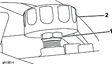
Clean around the oil filler cap/dipstick (Figure 18).
-
Remove the oil filler cap/dipstick by rotating it counterclockwise (Figure 18).
-
Wipe the oil filler cap/dipstick clean and insert it into filler port.
Note: Do not screw into port.
Important: Do not overfill the crankcase with oil because the engine may be damaged.
-
Remove and check level of oil.
Note: If oil level is near or below the lower limit mark on the dipstick, add only enough of the specified oil to raise level to the upper limit mark (bottom edge of the oil fill hole); refer to Figure 18.
-
Check level of oil (Figure 18).
-
Install the oil filler cap/dipstick and wipe up any spilled oil (Figure 18).
-
Install the cowl and secure the latches.
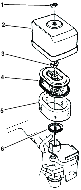
Servicing the Air Cleaner
| Maintenance Service Interval | Maintenance Procedure |
|---|---|
| Every 50 hours |
|
| Every 300 hours |
|
-
Disconnect the spark-plug wire.
-
Remove the wing nut that secures the air-cleaner cover to the air cleaner and remove the cover. Clean the cover thoroughly (Figure 19).
-
Remove the wing nut from the air filter and remove the filter (Figure 19).
-
Remove the foam filter from the paper filter (Figure 19).
-
Inspect both air-filter elements and replace them if they are damaged.
Note: Always replace the paper air-filter element at the scheduled interval.
-
Clean the foam element as follows:
-
Wash the foam element in a solution of liquid soap and warm water.
Note: Squeeze to remove dirt, but do not twist the element because the foam may tear.
-
Dry the element by wrapping in a clean rag. Squeeze the rag and foam element to dry, but do not twist the element because the foam may tear.
-
Saturate the element with clean engine oil. Squeeze element to remove excess oil and to distribute oil thoroughly.
-
-
Cleaning the paper element: Tap the filter element several times on a hard surface to remove dirt or blow compressed air (not exceeding 2.07 bar (30 psi) through the filter element from the inside. Never try to brush off dirt; brushing will force dirt into the fibers.
-
Install the foam element, paper element, and air-cleaner cover.
Important: Do not operate the engine without the air-cleaner element. Operating without an element causes damage to the engine.
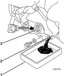
Changing the Engine Oil
| Maintenance Service Interval | Maintenance Procedure |
|---|---|
| After the first 50 hours |
|
| Every 100 hours |
|
Crankcase capacity: 1.1 L (1.16 US qt).
Oil type: API classification SJ or later.
Oil viscosity: selected the oil viscosity according to ambient temperature in the table below.
| Over 13° C (40° F) | SAE 30 or 10W30 |
| Below 13° C (40° F) | SAE 20 or 10W30 |
-
Start and run the engine for a few minutes to warm the engine oil; then, shut off the engine.
-
Have a funnel ready to place under the oil drain plug, then remove the plug and place the funnel under the plug to guide the oil into a container (Figure 20).
-
Install the drain plug and wipe away excess oil from the machine.
-
Fill the crankcase with the specified oil; refer to Figure 18 in Checking the Engine-Oil Level.
-
Dispose of the oil properly. Recycle the used oil according to local codes.
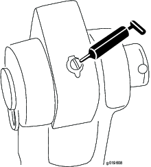
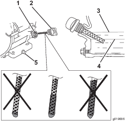
Replacing the Spark Plug
| Maintenance Service Interval | Maintenance Procedure |
|---|---|
| Every 100 hours |
|
| Every 300 hours |
|
Spark plug type: NGK BPR 6ES spark plug or equivalent.
Air gap: 0.70-0.80 mm (0.028-0.031 inch).
-
Remove the spark-plug wire.
-
Clean around spark plug and remove plug from cylinder head.
Important: Replace a cracked, fouled, or dirty spark plug. Do not sand blast, scrape, or clean electrodes because engine damaged could result from grit entering the cylinder.
-
Set the air gap at 0.70 to 0.80 mm (0.028 to 0.031 inch) (Figure 21). Install the spark plug carefully by hand to avoid cross-threading.

-
After the spark plug is seated, tighten it with a spark plug wrench to compress the sealing washer.
-
When installing a new spark plug, tighten 1/2 turn after the spark plug seats to compress the washer.
-
When installing the original spark plug, tighten 1/8 to 1/4 turn after the spark plug seats to compress the washer.
Note: A loose spark plug can overheat and damage the engine. Overtightening the spark plug can damage the threads in the cylinder head.
-
Connect the spark-plug wire.
Fuel System Maintenance
Cleaning the Sediment Cup
| Maintenance Service Interval | Maintenance Procedure |
|---|---|
| Every 100 hours |
|
Danger
In certain conditions, fuel is extremely flammable and highly explosive. A fire or explosion from fuel can burn you and others and can damage property.
-
Fill the fuel tank outdoors, in an open area, when the engine is cold. Wipe up any fuel that spills.
-
Do not fill the fuel tank completely full. Add fuel to the fuel tank until the level is 25 mm (1 inch) below the bottom of the filler neck. This empty space in the tank allows fuel to expand.
-
Never smoke when handling fuel, and stay away from an open flame or where fuel fumes may be ignited by a spark.
-
Store fuel in an approved container and keep it out of the reach of children. Do not use fuel that has been stored for more than 30 days.
-
Always place fuel containers on the ground away from your vehicle before filling.
-
Do not fill fuel containers inside a vehicle or on a truck or trailer bed because interior carpets or plastic truck bed liners may insulate the container and slow the loss of any static charge.
-
When practical, remove fuel-powered equipment from the truck or trailer and refuel the equipment with its wheels on the ground.
-
If this is not possible, then refuel such equipment on a truck or trailer from a portable container rather than from a fuel dispenser nozzle.
-
If you must use a fuel-dispenser nozzle, keep the nozzle in contact with the rim of the fuel tank or container opening at all times until fueling is complete.
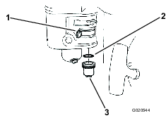
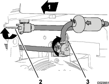
Changing the Fuel Filter
| Maintenance Service Interval | Maintenance Procedure |
|---|---|
| Every 300 hours |
|
-
Shut off the engine and engage the parking brake. Allow the engine to cool.
-
Rotate the lever for the tank-shutoff valve forward and up to the OFF position (Figure 23).
-
Start the engine and run the machine until the engine shuts off.
-
Rotate the lever for the engine switch clockwise to the STOP position, and allow the engine to cool (Figure 23).
-
Remove the spark-plug wire (Figure 24).
-
Remove the hose clamps and hose from the barbed fitting at fuel filter (Figure 25).
Note: Drain the fuel from the old fuel filter dispose of the fuel and filter at an authorized disposal site.
-
Align the arrow on the case of the new fuel filter to correspond with the fuel flow to the engine (Figure 25).
Note: Ensure that the hose clamps are slipped over the hoses attached to the engine fuel-shutoff valve and the tank-shutoff valve.
-
Insert the barbed fitting of the fuel filter into the hose from the engine switch (Figure 25).
-
Insert the barbed fitting at the other end of the fuel filter into the hose attached to the tank-shutoff valve (Figure 25).
-
Align the clamps over the hoses at the barbed area of the filter, and secure the clamps to the hoses.
-
Connect the spark-plug wire (Figure 24).
-
Open the tank-shutoff valve and turn on the engine switch, and check for fuel leaks (Figure 23).
Draining the Fuel Tank
| Maintenance Service Interval | Maintenance Procedure |
|---|---|
| Every 1,000 hours |
|
Danger
In certain conditions, fuel is extremely flammable and highly explosive. A fire or explosion from fuel can burn you and others and can damage property.
-
Drain fuel from the fuel tank when the engine is cold. Do this outdoors in an open area. Wipe up any fuel that spills.
-
Never smoke when draining fuel, and stay away from an open flame or where a spark may ignite the fuel fumes.
-
Shut off the engine and engage the parking brake. Allow the engine to cool.
-
Move the tank fuel-shutoff valve to the OFF position.
-
Remove the fuel sediment cup (Figure 22) and empty the fuel from it.
-
Move the tank fuel-shutoff valve (Figure 22) to the ON position, and drain the fuel from the fuel tank into a suitable container.
-
Replace the sediment cup and tighten securely (Figure 22).
-
Loosen the drain screw to drain fuel from the carburetor into a suitable container.
-
Install the drain screw when the carburetor is drained.
Drive System Maintenance
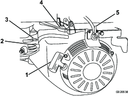
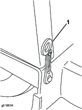
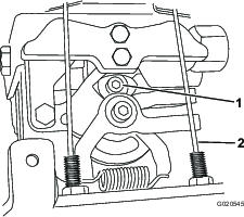
Adjusting the Transmission Return to Neutral Position
The hydrostatic transmission is equipped with a self-centering device that adjusts the transmission to the Neutral position, stopping the machine. If the machine creeps in one direction or the other when you release the controls, adjust the transmission. To adjust the transmission, use the following procedure:
-
Shut off the engine.
-
Remove the throttle lever cables at the transmission.
-
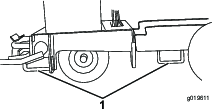
Lift the front wheels off the ground, and support the machine with a jack stand.
-
Start the machine. Increase the engine throttle to full speed while checking for front drive wheel rotation.
Note: If the wheels rotate, proceed to the next step. If the wheels do not rotate, shut off the engine and install the control cables.
-
Note the directional movement of the front drive wheels. Shut off the engine.
-
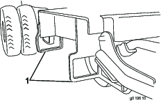
Loosen the lock down screw (Figure 26) until the return arm can be rotated.
Note: If wheels rotate forward, rotate the return arm counterclockwise. If wheels rotate backward, rotate the return arm clockwise.
-
Tighten the lock down screw and repeat step 4.
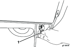
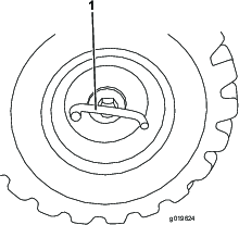
Checking the Tires and Lug Nuts
| Maintenance Service Interval | Maintenance Procedure |
|---|---|
| Every 40 hours |
|
-
Inspect tires for cuts, slashes, or bulges. Tires with defects need to be replaced or repaired for proper handling and safety.
-
Check weekly to make sure all lug nuts are tight. Torque the lug nuts to 122 N∙m (90 ft-lb). This is important on new machines or newly replaced wheels.
Controls System Maintenance
Brake Maintenance
Warning
If the brakes are not properly adjusted, serious injury or death may occur.
Check your brakes daily. If you encounter any problems with the brakes while operating the machine, shut off the machine immediately and take it to an Authorized Service Dealer for repair.
Checking the Service Brake
| Maintenance Service Interval | Maintenance Procedure |
|---|---|
| Before each use or daily |
|
-
Move the machine to a level, open area.
-
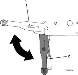
Pull the parking brake lever up to engage the brake and start the engine (Figure 27).
-
Set the engine throttle to the FAST position.
-
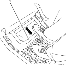
Step on the service brake pedal (Figure 28).
-
Push the parking brake lever down to disengage the brake (Figure 27).
-
Slowly squeeze the forward speed-control lever.
Note: The machine should not move forward.The engine should stall at full engagement of speed control.
-
Release the speed-control lever.
-
Slowly squeeze the reverse-speed-control lever.
Note: The machine should not move backward.The engine should stall at full engagement of speed control.
-
Release the speed-control lever.
-
If the machine moves forward or backward, have the machine repaired at an Authorized Service Dealer.
Checking the Parking Brake
| Maintenance Service Interval | Maintenance Procedure |
|---|---|
| Before each use or daily |
|
-
Park the machine on a level surface.
Note: Ensure that there is nothing in front of the machine.
-
Engage the parking brake (Figure 27).
-
Start the engine and set the throttle to fast.
-
Grasp the forward-speed-control lever.
Note: The engine should stall at full engagement of speed control and the machine should not move forward.
Note: If the machine moves forward, refer to Adjusting the Parking Brake.
-
Release the forward-speed-control lever.
-
Release the parking brake (Figure 27).
-
Grasp the forward-speed-control lever.
Note: The machine should move forward.
Note: If the machine does not move forward, refer to Adjusting the Parking Brake.
-
Repeat steps 2 through 7 for the reverse-speed-control lever.
-
Step on the service brake, engage the parking brake, and shut off the engine.
Adjusting the Parking Brake
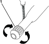
Turning the knob on the parking brake handle adjusts the parking brake.
-
Loosening the parking brake:(Figure 29).
-
Ensure that engine is off.
-
Step on the service brake pedal (Figure 28).
-
Disengage the parking brake (Figure 27).
-
Rotate the parking-brake knob counterclockwise (Figure 29).
Note: Rotate the knob no more than 1 revolution each time.
-
Test the parking brake; refer to Checking the Parking Brake.
-
Repeat steps 1 through 5 until the machine moves forward.
-
-
Tightening the parking brake: (Figure 29).
-
Shut off the engine.
-
Step on the service brake pedal (Figure 28).
-
Disengage the parking brake (Figure 27).
-
Rotate the parking-brake knob clockwise (Figure 29).
Note: Rotate the knob no more than 1 revolution each time.
-
Test the parking brake; refer to Checking the Parking Brake.
-
Repeat steps 1 through 5 until the machine does not move forward.
-
Hydraulic System Maintenance
Warning
Hydraulic fluid escaping under pressure can penetrate skin and cause injury. Fluid injected into the skin must be surgically removed within a few hours by a doctor familiar with this form of injury or gangrene may result.
-
Keep your body and hands away from pin hole leaks or nozzles that eject high-pressure hydraulic fluid.
-
Use cardboard or paper to find hydraulic leaks, never use your hands.
Checking the Hydraulic-Fluid Level
| Maintenance Service Interval | Maintenance Procedure |
|---|---|
| Before each use or daily |
|
Hydraulic fluid type: Mobil 424 Hydraulic Oil or equivalent
The machine hydraulic tank is filled at the factory with approximately 28.4 L (30 US qt) of hydraulic fluid.
Important: Always use the correct hydraulic fluid. Unspecified fluids will damage the hydraulic system.
-
Park the machine on a level surface and shut off the engine. Allow the engine to cool.
-
Unlatch and remove the cowl.
-
Ensure that the hopper is down and in the level position.
-
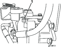
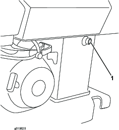
Locate the fluid sight gauge (Figure 30) on the side of the hydraulic fluid tank.
Note: When the fluid level is correct, the fluid level will cover 25% to 75% of the window in the sight gauge.
-
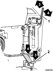
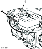
If the fluid level is low, remove the breather/filler cap from the top of the hydraulic tank (Figure 31) and add enough of the specified hydraulic fluid to raise it to the proper level.
Caution
The hydraulic breather/filler cap is designed to pressurize the reservoir to 34 kPa (5 psi).
Loosen the cap slowly to avoid injury whenever adding fluid or working on the hydraulic system. Use a wrench on the hex directly under the cap.
-
Install the breather/filler cap. Wipe up any spilled hydraulic fluid (Figure 31).
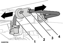
Replacing the Hydraulic Filter
| Maintenance Service Interval | Maintenance Procedure |
|---|---|
| Every 100 hours |
|
Important: Do not use an automotive oil filter or severe hydraulic system damage may result.
-
Park the machine on a level surface, engage the parking brake. and shut off the engine.
-
Unlatch and remove the cowl.
-
Place a drain pan under the filter (Figure 32).
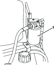
-
Remove the old filter (Figure 32) and wipe the surface of the filter adapter gasket clean.
-
Apply a thin coat hydraulic fluid to the rubber gasket on the replacement filter.
-
Install the replacement hydraulic filter onto the filter adapter (Figure 32). Tighten it clockwise until the rubber gasket contacts the filter adapter, then tighten the filter an additional 3/4 turn.
-
Clean up any spilled fluid.
-
Start the engine and let it run for 2 minutes to purge air from the system.
-
Shut off the engine and check for leaks.
-
Check the fluid level in the hydraulic tank, refer to Checking the Hydraulic-Fluid Level.
Note: Do not over fill the hydraulic tank.
-
Install the cowl and secure the latches.
Changing the Hydraulic Fluid
| Maintenance Service Interval | Maintenance Procedure |
|---|---|
| Every 200 hours |
|
Hydraulic fluid type: Mobil 424 Hydraulic Oil or equivalent
Hydraulic fluid capacity: 28.4 L (30 US qt)
Note: For temperatures below 1°C (35°F), the fluid should be switched to thinner 15 weight hydraulic fluid.
-
Park the machine on a level surface.
-
Allow the machine to cool completely.
-
Remove the hydraulic tank breather/filler cap (Figure 33).
Caution
The hydraulic breather/filler cap is designed to pressurize the reservoir to 34 kPa (5 psi).
Loosen the cap slowly to avoid injury whenever adding oil or working on the hydraulic system. Use a wrench on the hex directly under the cap.
-
Place a large drain pan under the drain plug located at the bottom of the hydraulic tank.
-
Remove the drain plug and allow the oil to drain into the pan.
-
When finished, install and tighten the drain plug.
Note: Dispose of the used oil at a certified recycling center.
-
Fill the hydraulic tank with approximately 28.4 liters (30 US quarts) of hydraulic fluid as specified previously.
-
Start the engine and let it run for a 2 to 3 minutes.
-
Shut off the engine.
-
Check the hydraulic fluid level and add more hydraulic fluid if necessary.
-
Install the cowl and secure the latches.
Checking the Hydraulic Lines
| Maintenance Service Interval | Maintenance Procedure |
|---|---|
| Every 40 hours |
|
| Every 1,500 hours |
|
Warning
Hydraulic fluid escaping under pressure can penetrate skin and cause injury. Fluid injected into the skin must be surgically removed within a few hours by a doctor familiar with this form of injury, or gangrene may result.
-
Keep your body and hands away from pinhole leaks or nozzles that eject high pressure hydraulic fluid.
-
Use cardboard or paper to find hydraulic leaks; never use your hands.
Cleaning
Removing Debris from the Machine
| Maintenance Service Interval | Maintenance Procedure |
|---|---|
| Before each use or daily |
|
Important: Operating the engine with blocked screens, dirty or plugged cooling fins, and/or cooling shrouds removed, will result in engine damage from overheating.
-
Park the machine on a level surface and shut off the engine. Allow the engine to cool.
-
Unlatch and remove the cowl.
-
Clean any debris from under the hopper.
-
Wipe away debris from the air cleaner.
-
Clean any debris buildup on the engine and in the transmission with a brush or blower.
Important: It is preferable to blow dirt out rather than washing it out. If you use water, keep it away from electrical items and hydraulic valves.Do not use a high-pressure washer. High-pressure washing can damage the electrical system and hydraulic valves or deplete grease.
-
Install the cowl and secure the latches.