
| Maintenance Service Interval | Maintenance Procedure |
|---|---|
| Before each use or daily |
|
Introduction
This is a multipurpose machine intended for use in various turf-maintenance activities. It is designed to operate a wide variety of attachments, each of which performs a specialized function. Using this product for purposes other than its intended use could prove dangerous to you and bystanders.
Read this information carefully to learn how to operate and maintain your product properly and to avoid injury and product damage. You are responsible for operating the product properly and safely.
Visit www.Toro.com for product safety and operation training materials, accessory information, help finding a dealer, or to register your product.
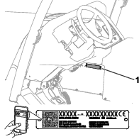
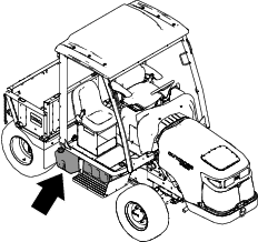
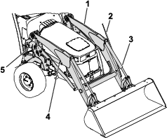
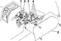
Whenever you need service, genuine Toro parts, or additional information, contact an Authorized Service Dealer or Toro Customer Service and have the model and serial numbers of your product ready. Figure 1 identifies the location of the model and serial numbers on the product. Write the numbers in the space provided.
Important: With your mobile device, you can scan the QR code on the serial number decal (if equipped) to access warranty, parts, and other product information.
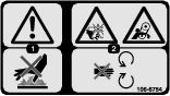
This manual identifies potential hazards and has safety messages identified by the safety-alert symbol (Figure 2), which signals a hazard that may cause serious injury or death if you do not follow the recommended precautions.

This manual uses 2 words to highlight information. Important calls attention to special mechanical information and Note emphasizes general information worthy of special attention.
This product complies with all relevant European directives; for details please see the separate product specific Declaration of Conformity (DOC) sheet.
It is a violation of California Public Resource Code Section 4442 or 4443 to use or operate the engine on any forest-covered, brush-covered, or grass-covered land unless the engine is equipped with a spark arrester, as defined in Section 4442, maintained in effective working order or the engine is constructed, equipped, and maintained for the prevention of fire.
The enclosed engine owner's manual is supplied for information regarding the US Environmental Protection Agency (EPA) and the California Emission Control Regulation of emission systems, maintenance, and warranty. Replacements may be ordered through the engine manufacturer.
Warning
CALIFORNIA
Proposition 65 Warning
Diesel engine exhaust and some of its constituents are known to the State of California to cause cancer, birth defects, and other reproductive harm.
Battery posts, terminals, and related accessories contain lead and lead compounds, chemicals known to the State of California to cause cancer and reproductive harm. Wash hands after handling.
Use of this product may cause exposure to chemicals known to the State of California to cause cancer, birth defects, or other reproductive harm.
Safety
Danger
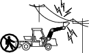
There may be buried utility lines or overhead lines in the work area. Contacting them may cause a shock or an explosion.
-
Have the property or work area marked for buried lines and do not dig in marked areas. Contact your local marking service or utility company to have the property marked (for example, in the US, call 811 or in Australia, call 1100 for the nationwide marking service).
-
Observe your work area for overhead power lines and avoid contact with them.
General Safety
This product is capable of causing personal injury. Always follow all safety instructions to avoid serious personal injury.
-
Read and understand the contents of this Operator’s Manual and any attachment manuals before starting the engine.
-
Use your full attention while operating the machine. Do not engage in any activity that causes distractions; otherwise, injury or property damage may occur.
-
Do not put your hands or feet near moving components of the machine.
-
Always keep attachments and loads as low as possible.
-
Do not operate the machine without all guards and other safety protective devices in place and functioning properly on the machine.
-
Keep children and bystanders out of the operating area. Never allow children and untrained operators to operate the machine.
-
Stop the machine, shut off the engine, remove the key, and wait for all moving parts to stop before servicing or fueling the machine.
Improperly using or maintaining this machine can result in injury.
To reduce the potential for injury, comply with these safety instructions
and always pay attention to the safety-alert symbol  , which means Caution, Warning,
or Danger—personal safety instruction. Failure to comply with
these instructions may result in personal injury or death.
, which means Caution, Warning,
or Danger—personal safety instruction. Failure to comply with
these instructions may result in personal injury or death.
Cab Classification for Protection from Hazardous Substances
This machine is equipped with a cab defined as Category 1 according to EN 15695-1. A Category 1 cab do not provide any protection against hazardous substances, and the machine should not be used in an environment with hazardous substances unless you do the following:
-
Use personal protective equipment (PPE).
-
Receive training and education about hazardous substances that you will be exposed to.
-
Keep used PPE and plant protection products (PPP) out of the cab.
-
Keep used gloves, shoes, and clothes out of the cab.
-
Keep the cab interior clean.
-
Follow instructions that are provided with PPE and PPP.
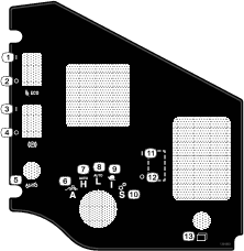
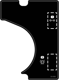
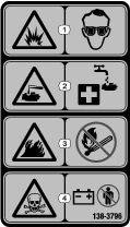
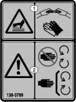
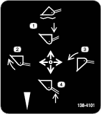
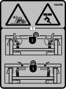
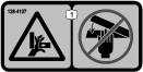
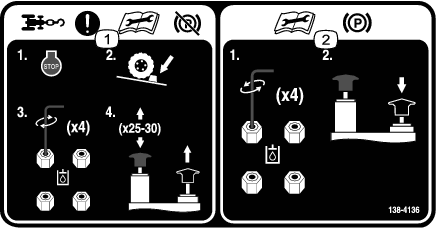
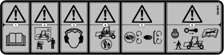
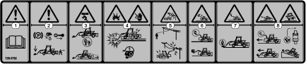
Safety and Instructional Decals
 |
Safety decals and instructions are easily visible to the operator and are located near any area of potential danger. Replace any decal that is damaged or missing. |


Setup
Note: Determine the left and right sides of the machine from the normal operating position.
Checking the Fluid Levels
Before you start the engine, perform the following fluid-level checks:
-
Check the engine-oil level; refer to Checking the Engine-Oil Level.
-
Check the coolant level; refer to Checking the Cooling System.
-
Check the hydraulic-fluid level; refer to Checking the Hydraulic-Fluid Level.
Checking the Tire Air Pressure
The tires may be over-inflated or under-inflated for shipping; therefore, you may have to adjust the air pressure in the tires. Refer to Checking the Tire Air Pressure.
Greasing the Machine
Grease the machine before use; refer to Greasing the Bearings and Bushings.
Important: Failure to properly grease the machine will result in premature failure of critical parts.
Installing the Hitch Linkage
Parts needed for this procedure:
| Top link | 1 |
| Draft link | 2 |
| Lift link | 2 |
| Sway link | 2 |
| Drawbar | 1 |
| Hammer strap | 1 |
| Screw (M18) | 2 |
| Washer | 2 |
| Hairpin cotter | 7 |
| Clevis pin | 9 |
| Lower pin | 2 |
| Lynch pin | 8 |
| Lift link pin | 3 |
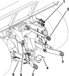
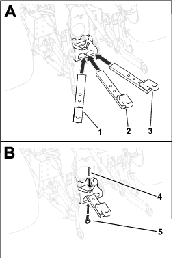
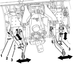
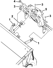
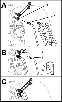
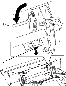
Installing the Sway, Draft, and Lift Links
Note: Figure 3 and Figure 4 show link installation on the left side of the machine. Repeat this procedure for the right side of the machine.
Note: Adjusting the lift links affects the parameter settings for all attachments. Maintain a 1 cm (3/8 inch) length of exposed thread.
-
Use a lift link pin and 2 lynch pins to secure the lift link to the machine lift arms (Figure 3).
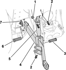
-
Install the draft link to the machine as follows:
-
Use a clevis pin and a lynch pin to secure the lift link to the draft link (Figure 3).
-
Use a clevis pin and a hairpin cotter to secure the sway links to the machine frame (Figure 4).
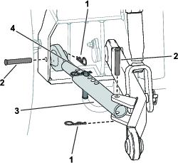
-
Use a clevis pin and a hairpin cotter to secure the sway link to the draft link (Figure 4).
-
Install a clevis pin and hairpin cotter to the sway link (Figure 4).
Use the pin and cotter to adjust the sway as needed for your attachment; refer to Adjusting the Sway Links.
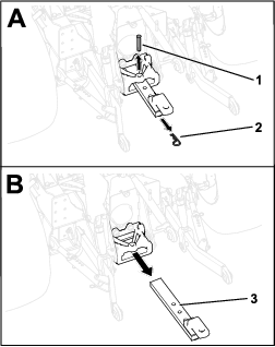
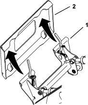
Installing the Drawbar
-
Use 2 screws (M18) and 2 washers to secure the hammer strap to the drawbar (Figure 5).
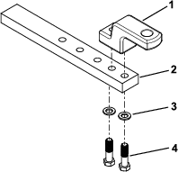
-
Torque the screws to 338 to 393 N∙m (250 to 290 ft-lb).
-
Install the drawbar to the drawbar support; refer to Installing the Drawbar Hitch.
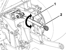
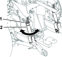
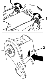
Installing the Top Link
-
Install the rod to the top link (Figure 6).
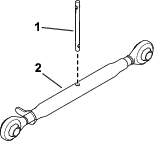
-
Install the top link to the upper-link bracket on the machine; refer to Installing or Removing the Top Link.
Product Overview
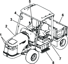
Become familiar with all the controls (Figure 8 and Figure 9) before you start the engine and operate the machine.
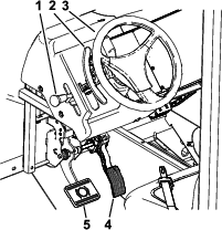
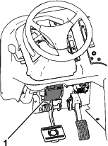
Accelerator Pedal
The accelerator pedal (Figure 8) gives you the ability to vary the engine and/or ground speed of the machine. Pressing the pedal increases the engine speed and ground speed. Releasing the pedal decreases the engine speed and ground speed of the machine.
Brake Pedal
Use the brake pedal (Figure 8) to stop or slow the machine.
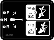
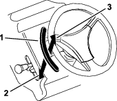
Shift Lever
Paddle Switch
When an attachment is not enabled, the paddle switch (Figure 11) raises and lowers the 3-point hitch.
Additionally, the paddle switch can handle multiple parameters when you have enabled and are using an attachment. The paddle switch can control the 3-point hitch, the 3-point-hitch height, PTO operation, attachment rate, and ground speed. Refer to the Software Guide for setting up attachment parameters.
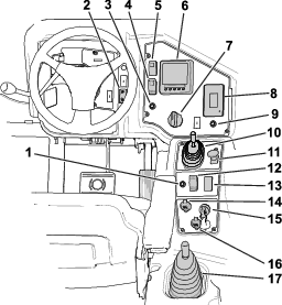
Key Switch
Use the key switch (Figure 9) to start and shut off the engine. It has 3 positions: OFF, ON, and START. Rotate the key clockwise to the START position to engage the starter motor. Release the key when the engine starts. The key moves automatically to the ON position.
To shut off the engine, rotate the key counterclockwise to the OFF position.
Parking-Brake Switch
Press the parking-brake switch (Figure 9) to engage or disengage the parking brake.
Note: The parking brake automatically engages when you shut off the engine.
InfoCenter
The InfoCenter LCD display (Figure 9) shows information about your machine, such as the operating status, attachment-parameter setup, various diagnostics, and other information about the machine.
When you start the machine, the screen appears and displays the corresponding icons that apply. The screens are dependent on which mode is selected with the operation-mode selector.
Refer to the machine Software Guide for more information.
Status Display
The status display (Figure 9) shows the status of the following machine information:
-
Fuel level
-
Active faults
-
3-point-attachment height and preset limits
-
Engine hours
-
Battery voltage
-
Engine speed
-
Engine coolant and hydraulic fluid temperatures
Press the status display switch (Figure 9) to toggle between data screens.
Refer to the machine Software Guide for more information.
Eco Mode Switch
Eco Mode improves fuel efficiency, decreases the sound level of the machine, and limits the engine speed to 2,300 rpm. Use this mode when in Automotive High or Automotive Low mode. Press the switch (Figure 9) to activate Eco Mode.
Operation-Mode Selector
Use the operation-mode selector (Figure 9) to select an operation mode. For a description of each mode, refer to Using the Operation-Mode Selector.
Light Switch
Use the light switch (Figure 9) to turn on and off the headlights. You can also use the switch to control lights from a kit; refer to the kit Installation Instructions.
Loader Joystick
If Equipped
Use the loader joystick (Figure 9) to control the front loader and attachment; refer to Using the Loader Joystick.
Power-Takeoff (PTO) Switch
Differential-Lock Switch
Press and hold the switch (Figure 9) to engage the differential lock; refer to Using the Differential Lock.
Cruise-Control Switch and Speed Increase/Decrease Switch
The cruise-control switch (Figure 9) sets the speed of the machine. Move the cruise-control switch to the center position to turn on the cruise control. Press the switch forward to set the speed. Press the switch rearward or press on the brake pedal to disengage the cruise control.
With the cruise control engaged, you can use the speed increase/decrease switch (Figure 9) to change the speed of the machine. The speed increase/decrease interval can differ depending on your current machine mode and use of attachments.
Refer to the following table for a description of the machine speed increase/decrease interval:
| Operating Mode | Speed |
| Automatic Low | 1.6 km/h (1 mph) |
| Automatic High | 1.6 km/h (1 mph) |
| Attachment Mode (using a rate-controlled attachment) | 0.2 km/h (0.1 mph) |
| Attachment Mode (using a non-rate-controlled attachment) | 0.8 km/h (0.5 mph) |
| Attachment Mode (not performing work with an attachment) | 1.6 km/h (1 mph) |
Automotive-Mode-Off Switch
When you press the automotive-mode-off switch (Figure 9) to turn off automotive mode, the engine operates at the maximum allowed speed. When pulling a large weight or approaching a steeper hill, it is best to turn off automotive mode to provide maximum engine power.
Auxiliary Hydraulic Lever
The auxiliary hydraulic lever (Figure 9) controls the hydraulic flow from the auxiliary ports located in the rear of the machine.
-
Moving the lever to the NEUTRAL position does not pressurize the top or bottom port.
-
Moving the lever to the RETRACT position pressurizes the bottom port.
-
Moving the lever to the FLOAT position locks the auxiliary ports in float mode.
-
Moving the lever to the EXTEND/CONTINUOUS RUN position pressurizes the top port and continuously runs the hydraulics.
Important: Leaving the lever in the EXTEND/CONTINUOUS RUN position with no attachment connected to the machine may cause a significant amount of heat to build up in the hydraulic system and damage the machine.
Important: When the cargo bed is installed, hold the lever in the forward position for 1 or 2 seconds after the box contacts the frame to secure it in the lowered position. Do not hold the lever in either the raise or lower position for more than 5 seconds once the cylinders have reached the end of their travel.
Power Point
Use the power point (Figure 9) to power optional 12 V electrical accessories.
Note: The power point does not provide power to your accessory when the key is removed from the switch.
USB Port
Insert your portable charger into the USB port (Figure 9) to charge a personal device, such as a phone or other electronic device.
Note: The USB port does not provide power to your accessory when the key is removed from the switch.
Adjusting the Operator’s Seat
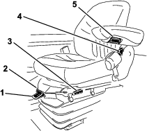
Seat-Position Adjustment Lever
Move the seat-position adjustment lever (Figure 14) on the side of the seat outward, slide the seat to the desired position, and release the lever to lock the seat into position.
Armrest Adjustment Knob
Rotate the knob (Figure 14) to adjust the armrest angle.
Seat-Back Adjustment Lever
Move the lever (Figure 14) to adjust the seat-back angle.
Weight Gauge
The weight gauge (Figure 14) indicates when the seat is adjusted to your weight. Adjust the height by positioning the suspension within the range of the green region.
Weight Adjustment Lever
Use this lever (Figure 14) to adjust the seat to your weight. Pull the lever up to increase the air pressure and push the lever down to decrease the air pressure. The proper adjustment is correct when the weight gauge is in the green region.
Cab Controls
For Machines with a Cab
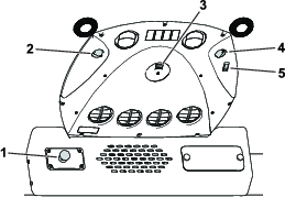
Windshield-Wiper Switch
Use this switch (Figure 15) to turn the windshield wipers on or off and control the wiper speed.
Press the switch in to spray the windshield with wiper fluid.
Fan-Control Knob
Rotate the fan-control knob (Figure 15) to regulate the speed of the fan.
Light Switch
Press the switch (Figure 15) to turn the dome light on or off.
Temperature-Control Knob
Rotate the temperature-control knob (Figure 15) to regulate the air temperature in the cab.
Air-Conditioning Switch
Use this switch (Figure 15) to turn the air conditioning on or off. Use the fan-control knob to control the air-conditioning.
Note: The engine rpm rises when you turn on the air-conditioning.
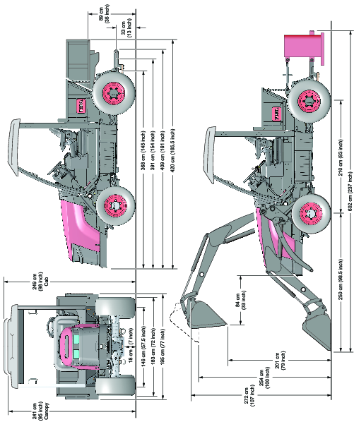
-
Refer to Figure 16 for the overall dimensions of the machine.
-
Refer to the Traction Unit table for additional dimensions.
| Description | Dimension, Weight, or Measurement | |
| Weight (dry) | Model 07511AA | Base: 2,340 kg (5,160 lb) |
| Model 07511BA | Base: 2,440 kg (5,380 lb) | |
| With loader and ballast box (mortar added) installed: 3,443 kg (7,590 lb) | ||
| Model 07511CA | Base: 2,581 kg (5,690 lb) | |
| Model 07511DA | Base: 2,681 kg (5,910 lb) | |
| With loader and ballast box (mortar added) installed: 3,683 kg (8,120 lb) | ||
| Gross vehicle weight | All models: 5,443 kg (12,000 lb) | |
| Maximum axle weight | Front axle (with loader): 4,535 kg (10,000 lb) | |
| Front axle (without loader): 2,268 kg (5,000 lb) | ||
| Rear axle: 3,175 kg (7,000 lb) | ||
| Rated capacity | Standard bed: 453 kg (1,000 lb) | |
| Cargo bed: 2,041 kg (4,500 lb) | ||
| Maximum ground speed | Forward: 34 km/h (21 mph) | |
| Reverse: 32 km/h (20 mph) | ||
-
For loader specifications, refer to Loader Specifications.
-
For 3-point hitch specifications, refer to 3-Point-Hitch Specifications.
Attachments/Accessories
A selection of Toro approved attachments and accessories is available for use with the machine to enhance and expand its capabilities. Contact your Authorized Service Dealer or authorized Toro distributor or go to www.Toro.com for a list of all approved accessories.
To ensure optimum performance and continued safety certification of the machine, use only genuine Toro replacement parts and accessories. Replacement parts and accessories made by other manufacturers could be dangerous, and such use could void the product warranty.
Operation
Before Operation
Before Operation Safety
General Safety
-
Never allow children or untrained people to operate or service the machine. Local regulations may restrict the age of the operator. The owner is responsible for training all operators and mechanics.
-
Become familiar with the safe operation of the equipment, operator controls, and safety signs.
-
Know how to stop the machine and shut off the engine quickly.
-
Only the operator and one passenger are allowed on the machine at the same time.
-
When entering and exiting the operator platform, use the step and handhold. Use care when mud, snow, or moisture is present.
-
Inspect all safety devices and decals. Do not operate the machine until all safety devices are in place and functioning properly and all decals are present and legible.
-
Chemical substances used may be hazardous and toxic.
Fuel Safety
-
Use extreme care in handling fuel. It is flammable and its vapors are explosive.
-
Extinguish all cigarettes, cigars, pipes, and other sources of ignition.
-
Use only an approved fuel container.
-
Do not remove the fuel cap or fill the fuel tank while the engine is running or hot.
-
Do not add or drain fuel in an enclosed space.
-
Do not store the machine or fuel container where there is an open flame, spark, or pilot light, such as on a water heater or other appliance.
-
If you spill fuel, do not attempt to start the engine; avoid creating any source of ignition until the fuel vapors have dissipated.
Performing Daily Maintenance
Before starting the machine each day, perform the Each Use/Daily procedures listed in Daily Maintenance Checklist.
Checking the Tire Air Pressure
The appropriate tire pressure varies with the use of the loader or aggressive tires; refer to the tire-air-pressure table below:
| Machine characteristic | Front tire pressure | Rear tire pressure |
| Loader equipped | 448 kPa (65 psi) | 152 kPa (22 psi) |
| Loader removed | 152 kPa (22 psi) | 152 kPa (22 psi) |
| Aggressive tires equipped | 448 kPa (65 psi) | 234 kPa (34 psi) |
Danger
Low tire pressure decreases machine side-hill stability. This could cause a rollover, which may result in personal injury or death.
Do not underinflate the tires.
Important: Maintain the recommended pressure in all tires to ensure proper machine performance. Do not underinflate the tires.Check the air pressure in all tires before operating the machine.
Checking the Safety-Interlock System
| Maintenance Service Interval | Maintenance Procedure |
|---|---|
| Before each use or daily |
|
The safety-interlock system prevents the engine from starting unless all of the following occurs:
-
You are sitting on the seat or the parking brake is engaged.
-
The power takeoff (PTO) is disengaged.
-
The auxiliary-hydraulic lever is in the center position.
-
The shift lever is in the NEUTRAL position
-
Your foot is off the accelerator pedal.
The machine is equipped with a warning buzzer that is used to notify you of certain machine conditions. The buzzer sounds when:
-
You leave the seat with the shift lever in the FORWARD or REVERSE positions;
-
You leave the seat with the traction pedal out of neutral;
-
You leave the seat with the parking brake disengaged and the PTO is engaged;
Caution
If the safety-interlock switches are disconnected or damaged, the machine could operate unexpectedly, causing personal injury.
-
Do not tamper with the interlock switches.
-
Check the operation of the interlock switches daily and replace any damaged switches before operating the machine.
Filling the Fuel Tank
Fuel Tank Capacity
Fuel tank capacity: 53 L (14 US gallons)
Fuel Specifications
Important: Use only ultra-low sulphur diesel fuel. Fuel with higher rates of sulfur degrades the diesel oxidation catalyst (DOC), which causes operational problems and shortens the service life of engine components.Failure to observe the following cautions may damage the engine.
-
Never use kerosene or gasoline instead of diesel fuel.
-
Never mix kerosene or used engine oil with the diesel fuel.
-
Never keep fuel in containers with zinc plating on the inside.
-
Do not use fuel additives.
Petroleum Diesel
Cetane rating: 45 or higher
Sulfur content: Ultra-low sulfur (<15 ppm)
| Diesel fuel specification | Location |
| ASTM D975 | USA |
| No. 1-D S15 | |
| No. 2-D S15 | |
| EN 590:96 | European Union |
| ISO 8217 DMX | International |
| BS 2869-A1 or A2 | United Kingdom |
| JIS K2204 Grade No. 2 | Japan |
| KSM-2610 | Korea |
-
Use only clean, fresh diesel fuel or biodiesel fuels.
-
Purchase fuel in quantities that can be used within 180 days to ensure fuel freshness.
Use summer-grade diesel fuel (No. 2-D) at temperatures above -7°C (20°F) and winter-grade fuel (No. 1-D or No. 1-D/2-D blend) below that temperature.
Note: Use of winter-grade fuel at lower temperatures provides lower flash point and cold flow characteristics which eases starting and reduces fuel filter plugging.Using summer-grade fuel above -7°C (20°F) contributes toward longer fuel pump life and increased power compared to winter-grade fuel.
Using Biodiesel
This machine can also use a biodiesel-blended fuel of up to B20 (20% biodiesel, 80% petrodiesel).
Sulfur content: Ultra-low sulfur (<15 ppm)
Biodiesel fuel specification: ASTM D6751 or EN14214
Blended fuel specification: ASTM D975, EN590, or JIS K2204
Important: The petroleum diesel portion must be ultra-low sulfur.
Observe the following precautions:
-
Biodiesel blends may damage painted surfaces.
-
Use B5 (biodiesel content of 5%) or lesser blends in cold weather.
-
Monitor seals, hoses, gaskets in contact with fuel as they may degrade over time.
-
Fuel filter plugging may occur for a time after you convert to biodiesel blends.
-
For more information on biodiesel, contact your authorized Toro distributor.
Adding Fuel
Fill the tank to about 6 to 13 mm (1/4 to 1/2 inch) below the top of the tank, not the filler neck, with the specified fuel as described in Fuel Specifications.
Note: If possible, fill the fuel tank after each use; this will minimize possible buildup of condensation inside the fuel tank.
Adjusting the Seat
Position the seat where you have the best control of the machine and are most comfortable. To adjust the seat, refer to Adjusting the Operator’s Seat.
Using the Differential Lock
Warning
Loss of control or damage to the machine or turf can happen if you do not properly use the differential lock.
-
Come to a complete stop to engage the differential lock.
-
Disengage the differential lock when driving on dry asphalt and concrete.
-
Use differential lock only when necessary for improved ground engagement.
Engaging the Differential Lock
-
Ensure that the machine is completely stopped.
-
Push and hold the differential-lock switch to engage the differential lock.
Note: The differential lock is only active when the differential-lock switch is pushed or the parking brake is engaged.
Note: The differential-lock icon
 appears in the InfoCenter when you engage the
differential lock.
appears in the InfoCenter when you engage the
differential lock.
Disengaging the Differential Lock
Disengage the differential lock by releasing the differential-lock switch.
Note: You can release the differential lock while the machine is in motion. The differential-lock may stay engaged while an axle load is present. The differential-lock will releases once you remove an axle load.
Adjusting the Hitch Linkage
Using the Drawbar Hitch
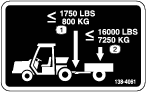
Understanding the Drawbar-Hitch Weight Capacities
Do not exceed the following weight capacities:
-
Maximum allowed transport load:
-
Attachments with brakes: 7,250 kg (16,000 lb)
-
Attachments without brakes: 1,497 kg (3,300 lb)
-
-
Vertical tongue weight: 800 kg (1,750 lb)
Removing the Drawbar Hitch
Installing the Drawbar Hitch
You can install the drawbar in a left-side-adjusted, right-side-adjusted, or centered position (Figure 21). Determine the appropriate drawbar position for your attachment, then install the drawbar as follows:
-
Insert the drawbar into the drawbar support (Figure 21).
-
Secure the drawbar to the support by inserting the clevis pin through the one of the three mount hole locations in the drawbar and attaching the hairpin cotter to the pin (Figure 21).
Note: Refer to your attachment Operator’s Manual for the correct drawbar position.
Using the Pintle Hitch
Optional
The Pintle Hitch Kit is available for use with your machine; see your authorized Toro distributor.
Adjusting the Top Link
Leveling an Attachment Front-to-Back
Note: If you are attaching a Category 1 attachment to the machine, the appropriate spaces and hubs must be utilized.
Installing or Removing the Top Link
Note: Refer to Figure 23 for this procedure.
Use the lynch pin and clevis pin to install the top link to the upper-link bracket; remove the pins to remove the top link from the upper-link bracket.
Adjusting the Lift Links
Leveling the Attachment Side-to-Side
Note: Adjusting the lift links affects the parameter settings for all attachments. Maintain a 1 cm (3/8 inch) length of exposed thread.
Adjusting the Sway Links
Note: Check the attachment Operator’s Manual for adjusting the sway procedure. For most implements, a small amount of sway (13 to 25 mm or 1/2 to 1 inch) is needed.
Note: If you are attaching a Category 1 attachment to the machine, the appropriate spaces and hubs must be utilized.
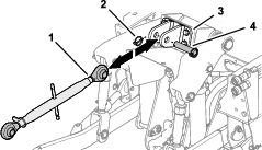
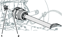
Connecting the Rear Power-Takeoff (PTO)
-
Park the machine on a level surface, move the shift lever to the NEUTRAL position, engage the parking brake, shut off the engine, and remove the key.
-
Align the quick-connect coupling of the driveshaft with the output shaft of the PTO (Figure 26).
Note: You can rotate the rear PTO enough to aid in the spline alignment.
-
Pull back the lock collar of the driveshaft yoke (Figure 27).
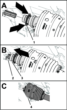
-
While pulling back the lock collar, push the driveshaft yoke forward and slip the socket of the yoke over the splines of the PTO output shaft (Figure 27).
-
Ensure that the lock at the driveshaft yoke snaps into the groove of the PTO output shaft securely.
-
Ensure that the shield is positioned over the driveshaft yoke (Figure 27).
Using the 3-Point Hitch
3-Point-Hitch Specifications
| Description | Specification |
| Category | 2 |
| Lift capacity | 1,135 kg (2,500 lb) |
| Lift point | 61 cm (24 inches) |
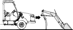
Installing a Rear 3-Point Attachment
Note: The InchMode Kit helps with installing a 3-point attachment. Contact your authorized Toro distributor for more information about the InchMode Kit.
-
Slowly back the machine up and align the draft links to the lower connections of the attachment (Figure 28).
-
Secure the draft links to the attachment (Figure 28).
-
Position the top link to the top connection of the attachment (Figure 28).
-
Secure the top link to the attachment (Figure 28).
-
After installing the attachment, level the attachment per the instructions in the attachments Operator’s Manual.
Removing a Rear 3-Point Attachment
-
Park the machine and attachment on a level surface.
-
Lower the attachment to the level surface.
-
Engage the parking brake and shut off the engine.
-
Remove the top link from the attachment (Figure 28).
-
Remove the draft links from the attachment (Figure 28).
-
Remove the pins from the sway links.
-
Start the engine, disengage the parking brake, and slowly drive the machine away from the attachment.
Using the Hydraulic Ports
Warning
Hydraulic fluid escaping under pressure can penetrate skin and cause injury. Seek immediate medical attention if fluid is injected into skin. Injected fluid must be surgically removed within a few hours by a doctor.
-
Ensure that all hydraulic-fluid hoses and lines are in good condition and all hydraulic connections and fittings are tight before applying pressure to the hydraulic system.
-
Keep your body and hands away from pinhole leaks or nozzles that eject high-pressure hydraulic fluid.
-
Use cardboard or paper to find hydraulic leaks; never use your hands.
Caution
Hydraulic couplers, hydraulic lines/valves, and hydraulic fluid may be hot. If you contact hot components, you may be burned.
-
Wear gloves when operating the hydraulic couplers.
-
Allow the machine to cool before touching hydraulic components.
-
Do not touch hydraulic fluid spills.
Connecting the Attachment Hydraulic Hoses
If an attachment requires hydraulic power for operation, connect the attachment hydraulic hoses as follows:
-
Shut off the engine and remove the key.
-
Move the auxiliary-hydraulic lever to the FLOAT position to relieve pressure at the hydraulic couplers.
-
Remove the protective covers from the hydraulic ports on the machine.
-
Ensure that all foreign matter is cleaned from the hydraulic ports.
-
Identify the quick-disconnect fittings for the rear attachment-extend and retract circuits for the tractor.
-
Identify the attachment extend and retract hoses.
-
Connect the quick-disconnect fitting of the attachment extend hose to the quick-disconnect fitting of the extend circuit (Figure 29).
-
Connect the quick-disconnect fitting of the attachment retract hose to the quick-disconnect fitting of the retract circuit (Figure 29).
-
Confirm that the connections are secure by pulling on the hoses.
Removing the Attachment Hydraulic Hoses
-
Engage the parking brake, lower any attachments (if equipped), shut off the engine, and remove the key.
-
Move the auxiliary-hydraulic lever to the FLOAT position to relieve pressure at the hydraulic couplers.
-
Pull back on the hydraulic port collars and remove the hoses from the hydraulic ports.
Note: A small amount of oil may remain between the port and hose ends. Have a rag available to wipe up any residual oil.
-
Clean the hydraulic ports and install the protective covers into the ports.
Adding Ballast to the Machine
Danger
To prevent personal injury or death from rollover when the machine is equipped with the loader, add the recommended amount of ballast to the machine.
-
Add the correct ballast to the hitch.
-
Use ballast to prevent the front axle or tractor components from overload during loader operation.
-
Always wear your seatbelt.
Determining the Ballast
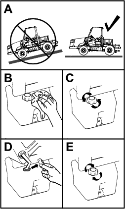
Add ballast to the hitch until the rear axle weight on level ground is at least 25% of the gross vehicle weight.
Use the following steps and formulas to determine the ballast:
-
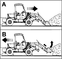
Put a full load in the bucket, lift the bucket to the furthest position forward as shown in Figure 30.
-
At a scale, measure the gross vehicle weight (GVW) at the front and rear axle, with the loader raised so that the bucket pivot pin is as high as the boom pivot pin (Figure 30).
-
Use the following formulas in the order listed in the table to calculate the amount of rear ballast.
Note: If R is less than required rear axle weight (RRAW), no ballast is required (Figure 30).If R is greater than RRAW, ballast is required (RBR).
Formulas
1 GVW = F + R 2 RRAW = GVW x 25% 3 RBR = RRAW – R 4 BR = RBR X 133% Abbreviations
Abbreviations for the formulas F Front axle weight R Rear axle weight GVW Gross vehicle weight RRAW Required rear axle weight RBR Rear ballast required BR Ballast required 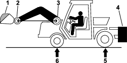
Filling the Ballast Box
-
Weight can be added to the ballast box by adding 0.3 m3 (10.4 ft3) of mortar.
Note: A 36 kg (80 lb) bag of mortar contains about 0.02 m3 (0.6 ft3) of mortar.
-
Do not add concrete or gravel to the ballast box.
-
If you need more weight, you may use additional weights.
Installing the Ballast Box
If you mount and operate the loader, you must first install the ballast box to the 3-point hitch. Refer to Installing a Rear 3-Point Attachment.
Removing the Ballast Box
Remove the ballast box before you remove the loader; refer to Removing a Rear 3-Point Attachment.
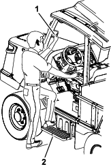
Entering the Machine
Warning
Improperly entering the machine can cause injury.
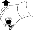
Always use the handle and step to enter the machine. To avoid injury while entering, maintain a 3-point contact: 1 hand on the handle and 2 feet on the step.
Enter the machine as shown in Figure 31.
During Operation
During Operation Safety
General Safety
-
The owner/operator can prevent and is responsible for accidents that may cause personal injury or property damage.
-
Your passenger should sit in the designated seating position only. Do not carry passengers in the standard or cargo bed. Keep bystanders and pets away from the machine during operation.
-
Wear appropriate clothing, including eye protection; long pants; substantial, slip-resistant footwear; and hearing protection. Tie back long hair and do not wear loose clothing or loose jewelry.
-
When using chemicals, use appropriate personal protective equipment (PPE). Refer to the instructions from the chemical manufacturer.
-
Do not operate the machine while ill, tired, or under the influence of alcohol or drugs.
-
Operate the machine outdoors or in a well-ventilated area only.
-
Do not exceed the maximum gross vehicle weight (GVW) of the machine.
-
Use extra caution when braking or turning the machine with a heavy load in the bed.
-
Carrying oversized loads in the bed reduces the stability of the machine. Do not exceed the carrying capacity of the bed.
-
Carrying material that cannot be bound to the machine, such as a large tank of liquid, may affect the steering, braking, and stability of the machine. When you carry material that cannot be bound to the machine, use caution when steering or braking.
-
Carry a reduced load and reduce the ground speed of the machine when operating on rough, uneven terrain, and near curbs, holes, and other sudden changes in terrain. Loads may shift, causing the machine to become unstable.
-
Before you start the engine, ensure that the transmission is in neutral, the parking brake is engaged, and you are in the operating position.
-
You and your passenger should remain seated with fastened seatbelts whenever the machine is moving. Keep your hands on the steering wheel; your passenger should use the handholds provided. Keep arms and legs within the machine body at all times.
-
Do not mount or dismount a moving machine.
-
Operate the machine only in good visibility. Watch for holes, ruts, bumps, rocks, or other hidden objects. Uneven terrain could overturn the machine. Tall grass can hide obstacles. Use care when approaching blind corners, shrubs, trees, or other objects that may obscure your vision.
-
Always watch out for and avoid low overhangs such as tree limbs, door jambs, overhead walkways, etc.
-
Look behind and down before reversing the machine to be sure of a clear path.
-
When using the machine on public roads, follow all traffic regulations and use any additional accessories that may be required by law, such as lights, turn signals, slow-moving vehicle (SMV) signs, and others as required.
-
If the machine ever vibrates abnormally, stop the machine immediately, shut off the engine, remove the key, wait for all movement to stop, and inspect for damage. Repair all damage to the machine before resuming operation.
-
It can take longer to stop the machine on wet surfaces than on dry surfaces.
-
Do not touch the engine, transmission, axles, exhaust pipe, diesel-particulate filter, or hydraulic components while the engine is running, or soon after you shut off the engine, because these areas may be hot enough to cause burns.
-
Use extreme caution when freeing a mired machine.
-
Inspect any chains and cables before using them. Failure of the chains, cables, and the tow bar present a serious hazard.
-
Use the drawbar on the towing machine when freeing a mired machine.
-
-
Do not leave a running machine unattended.
-
Before leaving the operating position, do the following:
-
Park the machine on a level surface.
-
Engage the parking brake.
-
Lower the cargo bed, loader, and attachments (if equipped).
-
Return the shift lever to the NEUTRAL position.
-
Shut off the engine and remove the key.
-
-
Do not operate the machine when there is the risk of lightning.
-
Keep hands, feet, and clothing away from the rotating attachment driveshaft.
-
Use only accessories approved by The Toro® Company.
Rollover Protection System (ROPS) Safety
-
Ensure that the seat belt is attached and that you can release it quickly in an emergency.
-
The operator and passenger must always wear their seatbelts.
-
Do not remove the ROPS from the machine.
-
Check carefully for overhead obstructions and do not contact them.
-
Keep the ROPS in safe operating condition by thoroughly inspecting it periodically for damage.
-
Do not operate the machine with a damaged ROPS. Do not repair or alter the ROPS.
-
The ROPS is an integral safety device.
Slope Safety
Slopes are a major factor related to loss-of-control and tip-over accidents, which can result in severe injury or death.
-
Survey the site to determine which slopes are safe for operating the machine and establish your own procedures and rules for operating on those slopes. Always use common sense and good judgment when performing this survey.
-
If you feel uneasy operating the machine on a slope, do not do it.
-
Keep all movement on slopes slow and gradual. Do not suddenly change the speed or direction of the machine.
-
Avoid operating the machine on wet terrain. Tires may lose traction. A rollover can occur before the tires lose traction.
-
If you begin to lose momentum while climbing a slope, gradually engage the brakes and slowly reverse the machine straight down the slope.
-
Turning on a slope can be dangerous. If you must turn on a slope, do it slowly and cautiously.
-
Loads and attachments affect stability on a slope.
-
Carry a reduced load and reduce your ground speed when operating on a slope.
-
Secure the load to the machine bed to prevent the load from shifting.
-
Take extra care when hauling loads that shift easily (e.g., liquids, rock, or sand).
-
-
Avoid starting, stopping, or turning the machine on a slope, especially with a load.
-
Stopping while going down a slope takes longer than stopping on level ground.
-
If you must stop the machine, avoid sudden speed changes, which can cause the machine to tip or roll over.
-
Do not engage the brakes suddenly when rolling rearward, as this may cause the machine to overturn.
-
-
Do not drive the machine near drop-offs, ditches, or embankments. The machine could suddenly roll over if a wheel goes over the edge or if the edge gives way.
Loading and Dumping Safety
-
Do not exceed the gross vehicle weight (GVW) of the machine when operating it with a load in the bed and/or towing a trailer; refer to Specifications.
-
Distribute the load in the bed evenly to improve the stability and control of the machine.
-
Before dumping the cargo bed (if equipped), ensure that there is no one behind the machine.
-
Do not dump a loaded cargo bed while the machine is sideways on a slope. The change in weight distribution may cause the machine to overturn.
Starting the Engine
Important: Do not attempt to push or tow the machine to get it started. Doing this cannot start the machine, and damage to the drive train could result.
-
Sit on the operator’s seat and engage the parking brake.
-
Disengage the PTO.
-
Move the shift lever to the NEUTRAL position.
-
Ensure that the auxiliary hydraulic lever is in the center position.
-
Keep your foot off the accelerator pedal.
-
Insert the key into the key switch and rotate it clockwise to start the engine.
Note: Release the key when the engine starts.
Driving the Machine
-
Disengage the parking brake.
-
Move the gear-shift lever to your desired position (FORWARD or REVERSE).
-
Press the accelerator pedal until you attain the desired speed.
Note: Avoid long periods of engine idling.
Stopping the Machine
To stop the machine, remove your foot from the accelerator pedal and press the brake pedal. As you press your foot further down on the pedal, the machine slows down quicker.
Shutting Off the Engine
Important: Allow the engine to idle for 2 minutes before shutting it off after a full-load operation. This allows the turbocharger to cool down before shutting off the engine. Failure to do so may damage the turbocharger.
-
Move the shift lever to the NEUTRAL position.
-
Rotate the key to the OFF position.
-
Engage the parking brake.
Note: The parking brake automatically engages when you turn off the engine.
-
Remove the key from the switch.
Caution
If you leave the key in the switch, someone could accidently start the engine and seriously injure you or other bystanders.
Remove the key from the switch when you leave the traction unit.
Using the Standard Bed
-
When loading the standard bed, distribute the load evenly.
-
Use extra caution if the load exceeds the dimensions of the machine/standard bed.
-
Operate the machine with extra caution when handling off-center loads that cannot be centered.
-
Keep loads balanced and secure to prevent them from shifting.
Using the Tailgate
To release the tailgate, pull the bed latches towards the center of the bed (Figure 32). You can lower the tailgate so that it rests on the bed or the rockshaft arms. While lowering the tailgate into the bed, you can lock the latches in toward the center of the bed by rotating the latches into their retainer slots.
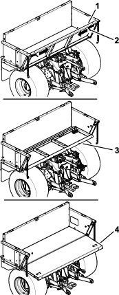
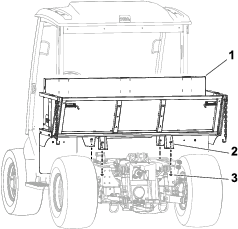
Removing or Installing the Standard Bed
The standard bed is secured to the chassis with bolts and nuts (Figure 33). Remove the hardware to remove the bed; use it to secure the bed to the chassis.
Caution
The standard bed is heavy; do not try to hoist it by yourself.
Use lifting equipment (e.g., an overhead hoist) to raise or lower the bed.
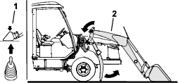
Using the Operation-Mode Selector
Note: The machine must come to a stop before you can change the modes.
Important: Leaving the machine in InchMode or Setup Mode disables the normal cleaning process of the diesel-particulate filter (DPF). Leaving the machine in either mode can plug the DPF and initiate a parked regeneration.
Use the mode selector to change the machine operation status or to set up attachments. The modes are as follows:
Attachment Mode
Use Attachment Mode to select the specific type of attachment or when attachments are installed and being moved to the work site. To access Attachment Mode, turn the operation-mode selector to the position (Figure 34).
Note: Changing attachments mounted to the Outcross may require the input of a pin number.
Note: Driving the machine in Attachment Mode operates the same as driving in Low Automotive Mode when the PTO switch is in the OFF AND DISABLED position and the auxilary hydraulic lever is in the NEUTRAL position.

High Automotive Mode
Use High Automotive Mode to drive the machine similar to a passenger vehicle with an automatic transmission. This mode provides the capacity for higher speed but lower power to the ground. Use this mode to efficiently transport yourself, a passenger, and a light payload.
To access High Automotive Mode, turn the operation-mode selector to the position (Figure 35).
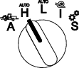
Low Automotive Mode
Use Low Automotive Mode to drive the machine similar to a passenger vehicle with an automatic transmission. This mode provides the capacity for higher payloads or steeper hill climbing speed at a lower ground speed. Use this mode to efficiently transport heavier payloads or trailers.
To access Low Automotive Mode, turn the operation-mode selector to the position (Figure 36).
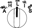
InchMode
If Equipped

Note: The InchMode setting is available through the use of an optional kit; see your authorized Toro distributor for more information.
Use the InchMode setting to aid in the connection of attachments to the machine. To access the InchMode setting, turn the operation-mode selector to the position (Figure 37).
To aid in the connection of attachments, locate and use the tethered remote to direct the machine forward or reverse, and to lift and lower the 3-point hitch. You can also engage the PTO.
Setup Mode
Use Setup Mode to access machine settings, service details, and basic machine information. You can also add or adjust the operational parameters of an attachment.
You can also use Setup Mode to attach and configure attachments. The engine stays at low idle when pressing the accelerator pedal and slowly moves the machine forward or in reverse. Pulling the PTO switch out engages the PTO (regardless of the current PTO parameter setting) and use the paddle to raise or lower the 3-point hitch.
To access Setup Mode, turn the operation-mode selector to the position (Figure 38).
The following are possible in Setup Mode:
-
You can move the vehicle at a very low speed and low engine rpm.
-
You can lift and lower the 3-point hitch beyond the settings allowed for the current attachment.
-
With the PTO driveline at a safe angle, you can engage the PTO output at a low engine rpm with the PTO switch.

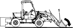
Using the Loader
If Equipped
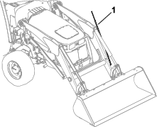
Refer to Figure 39 for an overview of the loader.
Loader Safety
-
Determine the appropriate attachment for the job.
-
Ensure that the attachment is securely attached to the machine.
-
Do not use this machine in a forestry operation.
-
Use your full attention while operating the loader. Do not engage in any activity that causes distractions; otherwise, injury or property damage may occur.
-
Never jerk the loader joystick; use a steady motion.
-
Avoid overhead power lines. Check for overhead clearance (i.e., electrical wires, branches, and doorways) before driving under any objects and do not contact them.
-
Before digging, check the location of cables, gas lines, and water lines.

-
While carrying materials, drive slowly. Rougher conditions may cause the material to spill.
-
Do not carry items that may move around in the loader bucket or attachment.
-
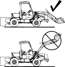
Carry a load as low as possible to the ground.
-
Do not lift or carry a person with the loader or any attachments.
-
A raised loader can fall unexpectedly. After operating the loader, lower the loader arms to the ground.
-
Relieve hydraulic pressure before you connect or disconnect the hydraulic couplers.
-
Detach and store the loader only on a hard, level surface.
-
Park the machine on a level surface, lower the loader to the ground, engage the parking brake, and shut off the engine after you operate the loader.
-
Do not leave the operator’s seat if any part of the machine contacts electric lines or cables.
-
Do not allow any bystanders near a raised loader.
Loader Specifications
| Description | Measurement |
| Lift capacity | 998 kg (2,200 lb) |
| Lift height | 272 cm (107 inches) |
| Reach at max lift height | 84 cm (33 inches) |
| Clearance with attachment in dump position | 201 cm (79 inches) |
| Clearance under level bucket | 254 cm (100 inches) |
| Reach with attachment on ground | 250 cm (99 inches) |
Note: Refer to Figure 16 in Specifications for an illustration of the lift height, reach, and clearance dimensions.
Removing the Loader
Danger
A detached loader can fall and cause serious injury or death.
-
Remove the loader on a hard, level surface.
-
Keep children and bystanders away from the detached loader.
-
Start the engine.
-
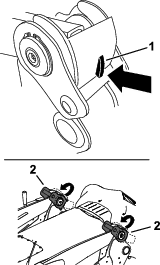
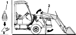
Relieve pressure on each loader-arm latch by rotating the loader attachment slightly forward and lowering it to the ground (Figure 44).
-
Press down on the latch lock on each loader-arm latch and raise the latches to unlock the loader arms from the machine (Figure 45).
-
Use the loader joystick to raise the loader arms out of the loader-frame mounts (Figure 46).
-
Engage the parking brake and shut off the engine.
-
Move the loader joystick to the left, right, and back to the NEUTRAL position to relieve pressure at the hydraulic couplers (Figure 47).
-
Perform the following steps to disconnect the hydraulic couplers (Figure 48):
-
Remove the male hose couplers by pulling back on the bulkhead and pulling out the male hose couplers.
-
Remove the female hose couplers by pulling back on the female-hose-coupler sleeves and pulling out the hose couplers from the bulkheads
-
Install the dust caps onto each coupler and bulkhead.
Important: Remove any dirt or debris from each coupler and bulkhead.
-
-
Place the hose bundle onto the hose-storage plate (Figure 49).
-
Start the engine, disengage the parking brake, and slowly drive away from the loader arms.
-
Remove the ballast box; refer to Removing a Rear 3-Point Attachment.
Installing the Loader
Danger
A detached loader can fall and cause serious injury or death.
-
Remove the loader on a hard, level surface.
-
Keep children and bystanders away from the detached loader.
-
Install the ballast box; refer to Installing a Rear 3-Point Attachment.
-
Start the engine and slowly drive the machine up to the loader arms (Figure 50).
Note: Ensure that the machine is centered between both sides of the loader arms.
-
Stop the machine, shut off the engine, and engage the parking brake.
-
Move the loader joystick to the left, right, and back to the NEUTRAL position to relieve pressure at the hydraulic couplers (Figure 51).
-
Perform the following steps to connect the hydraulic couplers (Figure 52):
-
Remove the dust caps from each coupler and bulkhead.
-
Locate the female and male couplers that have a cable tie secured to each coupler and note that these couplers must be installed to the top bulkheads that also have a cable tie secured to them.
-
Connect the male hose couplers by pulling back on the bulkhead and pushing in the male hose couplers to the bulkheads.
-
Connect the female hose couplers by pulling back on the female-hose-coupler sleeves and pushing in the hose couplers to the bulkheads
Important: Remove any dirt or debris from each coupler and bulkhead.
-
-
Start the engine and use the loader joystick to lower the loader arms into the loader-frame mounts (Figure 53).
-
Lock the loader arms to the machine by lowering each loader-arm latch so that the latch lock holds the latches in place (Figure 54).
Installing a Loader Attachment
Important: Attachments can change the stability and the operating characteristics of the machine.
Important: Before installing the attachment, ensure that the mount plates are free of any dirt or debris and that the pins rotate freely. If the pins do not rotate freely, grease them.
-
Position the attachment on a level surface with enough space behind it to accommodate the machine.
-
Rotate the quick-attach levers outward to raise the quick-attach pins.
-
Start the engine.
-
Tilt the attachment mount plate forward.
-
Position the mount plate into the upper lip of the attachment receiver plate (Figure 55).
-
Raise the loader arms while tilting back the mount plate at the same time.
Important: Raise the attachment enough to clear the ground and tilt the mount plate all the way back.
-
Shut off the engine and remove the key.
-
Rotate the quick-attach levers inward, ensuring that the quick-attach pins are fully seated in through the mount plate (Figure 56).
Warning
If you do not fully seat the quick-attach pins through the attachment mount plate, the attachment could fall off the machine, crushing you or bystanders.
Ensure that the quick-attach pins are fully seated in the attachment mount plate.
Removing a Loader Attachment
-
Park the machine on a level surface.
-
Lower the attachment to the ground.
-
Shut off the engine and remove the key.
-
Disengage the quick-attach pins by turning them to the outside.
-
If the attachment uses hydraulics, move the loader joystick forward, backward, and back to the NEUTRAL position to relieve pressure at the hydraulic couplers.
-
If the attachment uses hydraulics, slide the collars back on the hydraulic couplers and disconnect them.
Important: Connect the attachment hoses together to prevent hydraulic system contamination during storage.
-
Install the protective covers onto the hydraulic couplers on the machine.
-
Start the engine, tilt the mount plate forward, and back the machine away from the attachment.
Operating the Loader
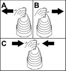
Using the Loader Joystick
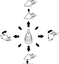
Note: Figure 57 illustrates the use of the joystick from the operator’s position.
-
To curl the attachment forward, slowly move the joystick to the right.
-
To curl the attachment rearward, slowly move the joystick to the left.
-
To lower the loader arms, slowly move the joystick forward.
-
To raise the loader arms, slowly move the joystick rearward.
-
To float the attachment, move the joystick fully forward.
Note: The float position raises and lowers the attachment according to the surface contours while you drive the machine.
By moving the joystick to an intermediate position (e.g., forward and left), you can move the loader arms and tilt the attachment at the same time.
Using the Attachment-Level Indicator
While you operate the loader, use the attachment-level indicator (Figure 58) to note the position of the attachment from the operator’s position. You can adjust the indicator for use with different attachments.
Lifting and Carrying a Load
To lift a load, move the loader joystick rearward to raise the loader arms, then move the joystick to the left to raise the bucket.
Always carry loads close to the ground (Figure 59).
Filling the Bucket
Refer to Figure 60 for this procedure.
-
Position the bucket level to the ground.
-
Drive forward and insert the bucket into the pile of material.
-
Move the shift lever to the REVERSE position.
-
Drive the machine in reverse while using the joystick to raise the loader arms and curl the bucket.
Dumping a Load
To dump a load, move the loader joystick to the right.
After dumping the load, back the machine away from the load and move the loader joystick up and to the left to lower and curl back the bucket.
Using Attachments
Note: Refer to the Software Guide for instructions on adding and editing attachment parameters.
Toro accepts no liability for machine damage or personal injury that results from the use of other manufacturer attachments. The user accepts the burden of these risks.
-
Each time an attachment or implement is mounted, check the 3-point-hitch movement. Ensure that there is no interference with hoses and attachment parts when operating the 3-point hitch.
Important: You can damage the PTO shaft if you operate attachments at too high or low of an angle. Always read the attachment Operator’s Manual for instructions on operating the PTO shaft.
-
Attachments can change the stability and the operating characteristics of the machine.
-
Keep your hands and feet away from moving attachments.
-
Locate the pinch point areas marked on the traction unit and attachments and keep your hands and feet away from these areas.
-
Read the attachment Operator’s Manual before you use the attachment.
Important: Incorrect PTO shaft length can cause machine and/or attachment damage and personal injury.
Danger
Entanglement in the rotating driveshaft can cause serious injury or death.
-
Keep hands and feet away from any rotating parts.
-
Ensure all guards are installed and all rotating shields rotate freely.
-
Before you perform adjustments or maintenance, shut off the engine, remove the key, wait for all moving parts to stop, and ensure that there is no movement in the driveshaft.
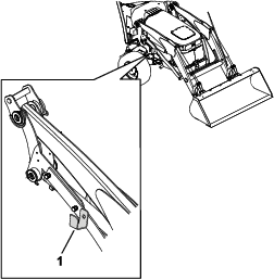
Towing an Attachment with the Machine
-
Before you tow an attachment, determine the maximum transport speed for the attachment; refer to the attachment Operator’s Manual.
-
Attachments without brakes:
-
Use Low Automotive Mode; refer to Low Automotive Mode.
-
Do not transport at a speed greater than 13 km/h (8 mph).
-
Ensure that the weight of the attachment or trailer is less than 1-1/2 t (3,300 lb) when fully loaded.
-
-
Attachments with brakes:
-
Use Low Automotive Mode; refer to Low Automotive Mode.
-
Do not transport at a speed greater than 13 km/h (8 mph).
-
Ensure that the weight of the attachment or trailer is less than 7-1/4 t (16,000 lb) when fully loaded.
-
Mount the brake controller to the area above the traction and brake pedals (Figure 61). Adjust the controller so that the braking ability is maximized for the attachment load size.
-
-
The machine is capable of pulling attachments of greater weight than the machine itself.
-
When hauling cargo or towing an attachment, do not overload your machine or attachment. Overloading can cause poor performance or damage to the brakes, axles, hydrostatic transmission, engine, steering, body structure, or tires.
Important: To reduce potential for drive line damage, use low range.
Understanding the Diesel-Particulate Filter and Regeneration
The diesel-particulate filter (DPF) removes soot from the engine exhaust.
The DPF regeneration process uses heat from the engine exhaust that is increased by the catalyst to reduce accumulated soot into ash.
To keep the DPF clean, remember the following:
-
Run the engine at full engine speed when possible to promote DPF self-cleaning.
Important: Leaving the machine in InchMode or Setup Mode (i.e., at a lower engine speed) disables the self-cleaning process of the DPF. Leaving the machine in either mode can plug the DPF and initiate a parked regeneration.
-
Use the correct engine oil.
-
Minimize the amount of time that you idle the engine.
-
Use only ultra low sulfur diesel fuel.
Operate and maintain your machine with the function of the DPF in mind. Engine under load generally produces adequate exhaust temperature for DPF regeneration.
Important: Minimize the amount of time that you idle the engine or operate the engine at low-engine speed to help reduce the accumulation of soot in the DPF.
Caution
The exhaust temperature is hot (approximately 600°C (1,112°F) during DPF regeneration. Hot exhaust gas can harm you or other people.
-
Do not operate the engine in an enclosed area.
-
Ensure that there are no flammable materials around the exhaust system.
-
Ensure that the hot exhaust gas does not contact surfaces that may be damaged by heat.
-
Do not touch a hot exhaust system component.
-
Do not stand near or around the exhaust pipe of the machine.
Understanding the Regeneration Icons
| Icon | Icon Definition |
 | • Parked or recovery regeneration icon-regeneration is requested. |
| • Perform the regeneration immediately. | |
 | • Notes that a regeneration is acknowledged |
 | • Notes that a regeneration is in progress and the exhaust temperature is elevated |
 | • Inhibit regeneration is selected |
 | • NOx control system malfunction; the machine requires service. |
Types of Diesel Particulate Filter Regeneration
| Type of Regeneration | Conditions that cause DPF regeneration | DPF description of operation |
|---|---|---|
| Reset | Occurs every 100 hours | • When the high exhaust-temperature icon  is displayed in the InfoCenter,
a regeneration is in progress. is displayed in the InfoCenter,
a regeneration is in progress. |
| Also occurs if normal engine operation surpasses the allowed soot accumulation amount within the filter | ||
| • During reset regeneration, the engine computer maintains an elevated engine speed to ensure filter regeneration. | ||
| • Avoid shutting off the engine and avoid using the machine in InchMode or Setup Mode while the reset regeneration is processing. |
| Type of Regeneration | Conditions that cause DPF regeneration | DPF description of operation |
|---|---|---|
| Parked | Occurs because the computer determines that the automatic DPF cleaning has not been sufficient. | • When the reset-standby/parked
or recovery regeneration icon  or a regeneration is requested. or a regeneration is requested. |
| Also occurs because you initiate a parked regeneration | ||
| May occur because the inhibit regen has been initiated and has disabled the automatic DPF cleaning from occuring | • Perform the parked regeneration as soon as possible to avoid needing a recovery regeneration. | |
| May result from using the incorrect fuel or engine oil | • A parked regeneration requires 30 to 60 minutes to complete. | |
| • You must have at least a 1/2 tank of fuel in the tank. | ||
| • You must park the machine to perform a parked regeneration. | ||
| Recovery | Occurs because the request for parked recovery has been ignored, allowing the DPF to be critically plugged | • When the reset-standby/parked or recovery
regeneration icon a recovery regeneration is requested. |
| • A recovery regeneration requires up to 3 hours to complete. | ||
| • You must have at least a 1/2 tank of fuel in the machine. | ||
| • You must park the machine to perform a recovery regeneration. |
Using the DPF Regeneration Menus
Accessing the DPF Regeneration Menus
-
Select the service menu icon in any mode and scroll to the REGENERATION option.
-
Select the regeneration function you need.
Time Since Last Regeneration
-
Access the DPF Regeneration menu, and scroll to the LAST REGEN option.
-
Select the LAST REGEN entry.
-
Use the LAST REGEN field to determine how many hours you have run the engine since the last reset, parked, or recovery regeneration.
-
Select the previous screen icon to return to the DPF regeneration screen.
Setting the Inhibit Regen
Reset Regeneration Only
A reset regeneration produces elevated engine exhaust. If you are operating the machine around trees, brush, tall grass, or other temperature-sensitive plants or materials, you can use the INHIBIT REGEN setting to prevent the engine computer from performing a reset regeneration.
Note: The INHIBIT REGEN option is always used when maintenance is being performed on the machine in an enclosed area.
Note: If you set the InfoCenter to inhibit regeneration, the InfoCenter displays an advisory every 15 minutes while the engine requests a reset regeneration.
Important: When you shut off the engine and start it again, the inhibit regen setting defaults to OFF.
-
Access the DPF Regeneration menu, and scroll down to the INHIBIT REGEN option.
-
Select the Inhibit REGEN entry.
-
Change the inhibit regeneration setting from Off to On.
Preparing to Perform a Parked or Recovery Regeneration
-
Ensure that the machine has fuel in the tank for the type of regeneration you are performing:
-
Parked Regeneration: Ensure that you have 1/4 tank of fuel before performing the parked regeneration.
-
Recovery Regeneration: Ensure that you have 1/2 tank of fuel before performing the recovery regeneration.
-
-
Move the machine outside to an area away from combustible materials or items that may be damaged by heat.
-
Park the machine on a level surface.
-
Ensure that the shift lever is in the NEUTRAL position.
-
Disengage the PTO, and lower any attachments (if equipped).
-
Engage the parking brake.
-
Set the throttle to the low IDLE position.
-
Move the operation-mode selector to the H or L position.
-
Ensure that the air-conditioning is off.
Performing a Parked or Recovery Regeneration
When a parked regeneration is requested by the engine computer, follow the messages on the InfoCenter.
Important: The computer of the machine cancels DPF regeneration if you increase the engine speed from low idle or release the parking brake.
-
Access the DPF Regeneration menu, and scroll down to the PARKED REGEN option or the RECOVERY REGEN option.
-
Select the PARKED REGEN entry or the RECOVERY REGEN entry.
Note: Initiating a recovery regeneration requires you to enter the correct PIN code.
-
At the VERIFY FUEL LEVEL screen, verify that you have 1/4 tank of fuel if you are performing the parked regeneration or 1/2 tank of fuel if you are performing the recovery regeneration, and press the next screen icon to continue.
-
On the Parked Regen menu or Recovery Regen menu, press the next screen to start the regeneration.
-
At the DPF checklist screen, verify that the parking brake is engaged, that the engine speed is set to low idle, and press the next screen icon to continue.
-
At the INITIATE DPF REGEN screen, select the next screen icon to continue.
-
The InfoCenter displays the INITIATING DPF REGEN message.
Note: If needed, press the cancel icon to cancel the regeneration process.
-
The InfoCenter displays the time to complete message.
-
The InfoCenter displays the home screen and the regeneration acknowledge icon appears
.Note: While the DPF regeneration runs, the InfoCenter displays the high exhaust-temperature icon
. -
When the engine computer completes a parked or recovery regeneration, the InfoCenter displays an advisory. Press any button to exit to the home screen.
Note: If the regeneration fails to complete, follow the advisory and press any button to exit to the home screen.
Canceling a Parked or Recovery Regeneration
Use the PARKED REGEN CANCEL or RECOVERY REGEN CANCEL setting to cancel a running parked or recovery regeneration process.
-
Access the DPF Regeneration menu, scroll down to the PARKED REGEN option or the RECOVERY REGEN option.
-
Press the next screen to cancel a Parked Regen or cancel a Recovery Regen.
After Operation
After Operation Safety
-
Before leaving the operating position, do the following:
-
Park the machine on a level surface.
-
Move the shift lever to the NEUTRAL position.
-
Engage the parking brake.
-
Lower all attachments.
-
Shut off the engine and remove the key.
-
-
Allow the engine to cool before storing the machine in any enclosure.
-
Do not store the machine where there is an open flame, spark, or pilot light.
-
Keep all parts of the machine in good working condition and all hardware tightened.
-
Maintain and clean the seat belts as necessary.
-
Replace all worn, damaged, or missing decals.
Exiting the Machine
Warning
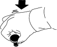
Improperly exiting the machine can cause injury.
Always use the handle and step to exit the machine. To avoid injury while exiting, maintain a 3-point contact: 1 hand on the handle and 2 feet on the step.
Exit the machine as shown in Figure 62.
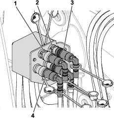
Towing the Machine
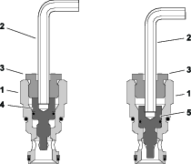
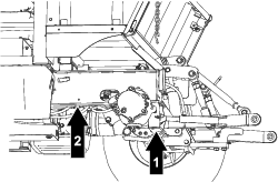
Note: A hex wrench (6 mm) is provided with the machine and is located next to the hydraulic manifold (Figure 63). Use the wrench to perform this procedure.
If it becomes necessary to tow the machine, you must set the tandem piston (traction) pump to bypass hydraulic fluid and manually pressurize the hydraulic brake circuit to release the brake. Move the machine a very short distance at a speed below 3.2 kph (2 mph). If you need to move the machine more than a short distance, transport the machine on a trailer.
Important: If towing limits are exceeded, severe damage to the piston (traction) pump may occur.
Important: Do not start or run the engine when the plugs are set to the bypass position.
-
Chock the tires to prevent the machine from moving
-
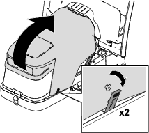
Remove the access panel from the right side of the control console (Figure 63).
-
Set the plungers to the bypass position by inserting a hex wrench (6 mm) through the plug assembly and turning the plunger all the way in clockwise; refer to Figure 64. Repeat this step for each plug assembly (4 total).
-
To release the brake, lift and hold the manual valve while pumping the hand pump.
-
Pump the hand pump until you feel resistance. When enough pressure has been created, the manual valve will remain in the raised position and the brake will be released.
-
Remove the chocks from the tires and tow the machine.
-
After towing and before starting the engine, insert a hex wrench (6 mm) through the plug assembly and turn the plunger all the way out counterclockwise. Repeat this step for each plug assembly (4 total).
-
Push the manual valve down to engage the parking brake.
-
Install the access panel.
Hauling the Machine
-
Remove the key before storing or transporting the machine.
-
Ensure that you have a truck or trailer that is large enough to handle the machine and any attachments.
-
Use care when loading or unloading the machine into a trailer or a truck.
-
Use full-width ramps for loading the machine into a trailer or a truck.
-
Use the tie-down loops on the machine (Figure 65) to securely tie the machine down.
Important: Do not use the tie-down loops to lift the machine. Refer to Raising the Machine for instructions to lift the machine.
-
Ensure that the trailer or truck has all the necessary brakes, lighting, and marking as required by law.
-
Refer to your local ordinances for trailer and tie-down requirements
Warning
Driving on the street or roadway without turn signals, lights, reflective markings, or a slow-moving-vehicle emblem is dangerous and can lead to accidents causing personal injury.
Install and use the correct accessories when driving on a public street or roadway.
Maintenance
Maintenance Safety
-
Before adjusting, cleaning, repairing, or leaving the machine, do the following:
-
Park the machine on a level surface.
-
Move the shift lever to the NEUTRAL position.
-
Engage the parking brake.
-
Lower all attachments to the ground and move the auxiliary-hydraulic lever to the FLOAT position.
-
Remove the loader (if equipped); refer to Removing the Loader.
-
Ensure that the DPF regeneration is inhibited; refer to Setting the Inhibit Regen.
-
Shut off the engine and remove the key.
-
Wait for all moving parts to stop.
-
Allow machine components to cool before performing maintenance.
-
-
If possible, do not perform maintenance while the engine is running. Keep away from moving parts.
-
Use jack stands to support the machine or components when required.
-
Carefully release pressure from components with stored energy.
Recommended Maintenance Schedule(s)
| Maintenance Service Interval | Maintenance Procedure |
|---|---|
| After the first hour |
|
| After the first 10 hours |
|
| After the first 100 hours |
|
| After the first 150 hours |
|
| After the first 200 hours |
|
| After the first 250 hours |
|
| After the first 1000 hours |
|
| Before each use or daily |
|
| Every 50 hours |
|
| Every 100 hours |
|
| Every 300 hours |
|
| Every 400 hours |
|
| Every 500 hours |
|
| Every 800 hours |
|
| Every 1,000 hours |
|
| Every 1,500 hours |
|
| Every 2 years |
|
Pre-Maintenance Procedures
Raising the Machine
Danger
Mechanical or hydraulic jacks may fail to support the machine and cause a serious injury.
-
Use jack stands to support the raised machine.
-
Use only mechanical or hydraulic jacks to lift the machine.
Raising the Front of the Machine
-
Chock the 2 rear wheels with chocks to prevent the machine from moving.
-
Position the jack securely under the desired front jacking point.
-
After raising the front of the machine, use an appropriate jack stand under the machine frame to support the machine.
Raising the Rear of the Machine
-
Chock the 2 front wheels with chocks to prevent the machine from moving.
-
Position the jack securely under the desired rear jacking point.
-
After raising the rear of the machine, use an appropriate jack stand under the machine frame to support the machine.
Lubrication
Greasing the Bearings and Bushings
| Maintenance Service Interval | Maintenance Procedure |
|---|---|
| Every 50 hours |
|
The machine has grease fittings that you must lubricate regularly with No. 2 lithium grease.
Important: Lubricate the machine immediately after every washing.
Traction Unit
Grease point locations and quantities are as follows:
-
Upper and lower kingpin (8)
-
Outer tie rod (4)
-
Front-axle pivot (2)
-
PTO driveshaft (1)
-
Rockshaft tube (1)
-
3-point-hitch lift cylinder (2)
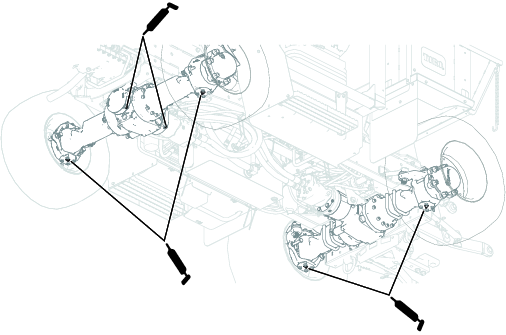
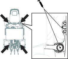
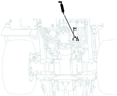
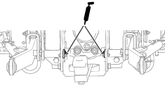
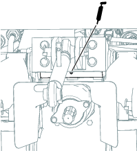
Loader
Grease point locations and quantities are as follows:
-
Lift cylinder (4)
-
Attachment cylinder (4)
-
Loader arm (2)
-
Mount-plate bushings (4)
-
Attachment coupler (2)
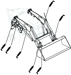
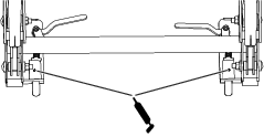
Engine Maintenance
Engine Safety
-
Ensure that the DPF regeneration is inhibited; refer to Setting the Inhibit Regen.
-
Shut off the engine and remove the key before checking the oil or adding oil to the crankcase.
Servicing the Engine Oil
Understanding the Engine-Oil Specifications
Oil Type: Use high-quality, low-ash engine oil that meets or exceeds the following specifications:
-
API service category CJ-4 or higher
-
ACEA service category E6
-
JASO service category DH-2
Important: Using engine oil other than API CJ-4 or higher, ACEA E6, or JASO DH-2 may cause the diesel particulate filter to plug or cause engine damage.
Crankcase Capacity: Approximately 5.7 L (6 US qt) with the filter.
Viscosity: Use the following engine oil viscosity grade:
-
Preferred oil: SAE 15W-40 (above 0°F)
-
Alternate oil: SAE 10W-30 or 5W-30 (all temperatures)
Toro Premium Engine Oil is available from your authorized Toro distributor in either 15W-40 or 10W-30 viscosity grades. See the Parts Catalog for part numbers.
Checking the Engine-Oil Level
| Maintenance Service Interval | Maintenance Procedure |
|---|---|
| Before each use or daily |
|
The engine is shipped with oil in the crankcase; however, the oil level must be checked before and after the engine is first started.
You can check the oil without raising the hood by reaching through the engine shield on the right side of the machine (Figure 77) and pulling out the dipstick from the engine. If you must add additional engine oil, you must raise the hood; refer to Raising the Hood.
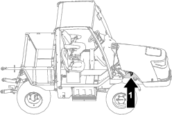
Important: Check the engine oil daily. If the engine-oil level is above the Full mark on the dipstick, the engine oil may be diluted with fuel;If the engine-oil level is above the Full mark, change the engine oil.
The best time to check the engine oil is when the engine is cool before it has been started for the day. If it has already been run, allow the oil to drain back down to the sump for at least 10 minutes before checking. If the oil level is at or below the Add mark on the dipstick, add oil to bring the oil level to the Full mark. Do not overfill the engine with oil.
Important: Keep the engine-oil level between the upper and lower limits on the dipstick; the engine may fail if you run it with too much or too little oil.
Check the engine-oil level; refer to Figure 78.
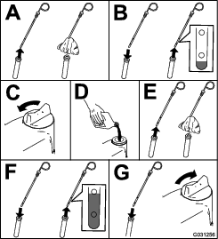
Note: When using different oil, drain all old oil from the crankcase before adding new oil.
Changing the Engine Oil and Filter
| Maintenance Service Interval | Maintenance Procedure |
|---|---|
| After the first 250 hours |
|
| Every 300 hours |
|
| Every 400 hours |
|
| Every 500 hours |
|
-
Start the engine and let it run 5 minutes to allow the oil to warm up.
-
With the machine parked on a level surface, shut off the engine, remove the key, and wait for all moving parts to stop before leaving the operating position.
-
Replace the engine oil and filter (Figure 79).
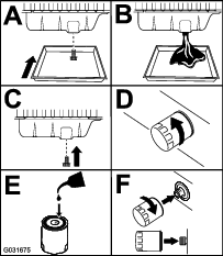
-
Add oil to the crankcase.
Servicing the Air Cleaner
| Maintenance Service Interval | Maintenance Procedure |
|---|---|
| Before each use or daily |
|
| Every 50 hours |
|
| Every 400 hours |
|
Check the air-cleaner body for damage, which could cause an air leak. Replace the body if it is damaged. Check the intake system for leaks, damage, or loose hose clamps.
Service the air-cleaner filter only when the service indicator (Figure 80) requires it. Changing the air filter before it is necessary increases the chance of dirt entering the engine when you remove the filter.
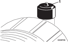
Important: Ensure that the cover is seated correctly and seals with the air-cleaner body.
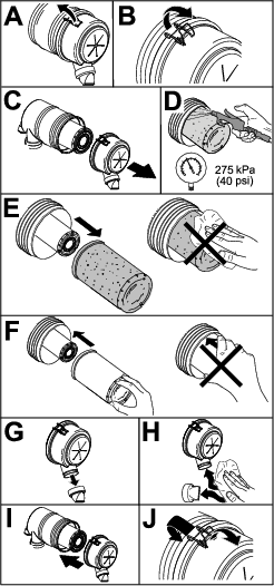
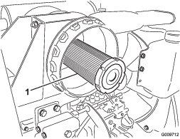
Fuel System Maintenance
Servicing the Fuel System
Emptying the Fuel Tank
| Maintenance Service Interval | Maintenance Procedure |
|---|---|
| Every 800 hours |
|
Empty and clean the tank also if the fuel system becomes contaminated or if you are storing the machine for an extended period of time. Use clean fuel to flush out the tank.
Inspecting the Fuel Lines and Connections
| Maintenance Service Interval | Maintenance Procedure |
|---|---|
| Every 400 hours |
|
Inspect the fuel lines and connections for deterioration, damage, or loose connections.
Servicing the Water Separator
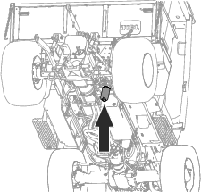
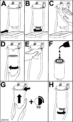
Servicing the Fuel Filter
| Maintenance Service Interval | Maintenance Procedure |
|---|---|
| Every 400 hours |
|
-
Clean the area around the fuel-filter head (Figure 85).
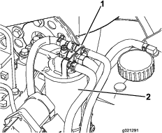
-
Remove the filter and clean the filter head mounting surface (Figure 85).
-
Lubricate the filter gasket with clean lubricating engine oil; refer to the engine owner's manual for additional information.
-
Install the dry filter canister by hand until the gasket contacts the filter head, then rotate it an additional 1/2 turn.
-
Start the engine and check for fuel leaks around the filter head.
Electrical System Maintenance
Electrical System Safety
-
Disconnect the battery before repairing the machine. Disconnect the negative terminal first and the positive last. Connect the positive terminal first and the negative last.
-
Charge the battery in an open, well-ventilated area, away from sparks and flames. Unplug the charger before connecting or disconnecting the battery. Wear protective clothing and use insulated tools.
Accessing the Battery
The battery is located underneath the side cover on the left side of the machine. To gain access to the battery, remove the knobs and washers that secure the cover to the machine chassis (Figure 86).
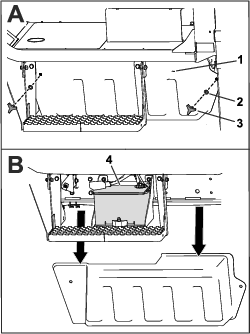
Disconnecting the Battery
Warning
Battery terminals or metal tools could short against metal components, causing sparks. Sparks can cause the battery gasses to explode, resulting in personal injury.
-
When removing or installing the battery, do not allow the battery terminals to touch any metal parts of the machine.
-
Do not allow metal tools to short between the battery terminals and metal parts of the machine.
Warning
Incorrect battery cable routing could damage the machine and cables causing sparks. Sparks can cause the battery gasses to explode, resulting in personal injury.
Always disconnect the negative (black) battery cable before disconnecting the positive (red) cable.
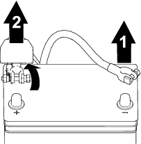
Connecting the Battery
Warning
Incorrect battery cable routing could damage the machine and cables causing sparks. Sparks can cause the battery gasses to explode, resulting in personal injury.
Always connect the positive (red) battery cable before connecting the negative (black) cable.
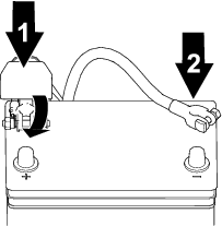
Removing and Installing the Battery
A retainer (Figure 89) holds the battery in the tray. Loosen the retainer hardware to remove the battery; tighten it when installing the battery.
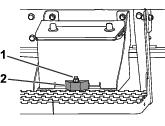
Checking the Battery Condition
| Maintenance Service Interval | Maintenance Procedure |
|---|---|
| Every 50 hours |
|
Important: Before welding on the machine, disconnect the negative cable from the battery to prevent damage to the electrical system.
Check the battery condition weekly or after every 50 hours of operation. Keep the terminals and the entire battery case clean, as a dirty battery will discharge slowly.
-
Access the battery; refer to Accessing the Battery.
-
Remove the rubber insulator from the positive terminal and inspect the battery. If the battery is dirty, do the following steps:
-
Wash the entire case with a solution of baking soda and water.
-
Coat both battery posts and cable connectors with Grafo 112X (skin-over) grease (Toro Part No. 505-47) to prevent corrosion.
-
Slide the rubber boot over the positive terminal.
-
Close the battery cover.
-
Locating the Fuses
Locating the Traction Unit Fuses
The traction-unit fuses are located under the steering wheel and above the traction and brake pedals (Figure 90).
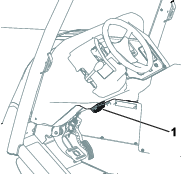
Refer to the following table for a description of each fuse on the machine fuse block:
| A | B | C | D | |
| 1 | Primary T1 Power 2 (7.5 A) | Primary T1 Power 3 (7.5 A) | Primary T1 Power 4 (7.5 A) | Primary T1 Power 5 (7.5 A) |
| 2 | Engine ECU power (10 A) | Primary T1 (2 A) | Expansion power (10 A) | EU hazard lights (15 A) |
| 3 | System power (10 A) | InfoCenter (2 A) | Headlights (15 A) | Power point; Selective control valve (10 A) |
| 4 | Status display (2 A) | Hazard lights (10 A) | Horn (10 A) | Beacon (10 A) |
| 5 | Air-ride seat (10 A) | Trailer brake control (20 A) | Expansion power (10 A) | Rear auxiliary power (15 A) |
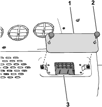
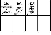
Drive System Maintenance
Servicing the Axles
Hub-and-axle oil specification: Toro Premium Tractor Fluid
Checking the Oil Level in the Wheel Hubs
| Maintenance Service Interval | Maintenance Procedure |
|---|---|
| After the first 100 hours |
|
| Every 400 hours |
|
Note: Have another person help you align the oil plugs in the wheel hubs when you service the axle oil.
-
Ensure that the machine is on a level surface and remove any equipped attachments.
-
Move the machine forward or backward until the plug for the wheel hub is at either the 10 o’clock or 2 o’clock position (Figure 93).
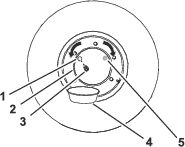
-
Shut off the engine, move the shift lever to the NEUTRAL position, engage the parking brake, and remove the key.
-
Place a drain pan under the drain port in the wheel hub (Figure 93).
-
Remove the plug from the wheel hub (Figure 93).
-
Check that the oil level is at the bottom of the threads of the oil port (Figure 93).
-
If the oil level is too high, allow the oil to drain from the oil port.
-
If the oil level is too low, add the specified oil to the wheel hub through the oil port; refer to step 8 in Changing the Oil in the Wheel Hubs.
-
-
Check the condition of the O-ring on the plug.
Note: Replace the plug if the O-ring is worn or damaged.
-
Install the plug in the oil port of the wheel hub (Figure 93).
-
Repeat steps 2 through 8 for the other wheel hubs.
Changing the Oil in the Wheel Hubs
| Maintenance Service Interval | Maintenance Procedure |
|---|---|
| After the first 150 hours |
|
| Every 1,000 hours |
|
| Every 1,500 hours |
|
Wheel hub oil capacity: approximately 0.4 L (0.4 US qt)
Note: If possible, change the oil when it is warm.
-
Move the machine forward or backward until the oil plug for the wheel hub is at the 12 o’clock position; refer to Figure 93 in Checking the Oil Level in the Wheel Hubs.
-
Partially unscrew the oil plug to release any pressure.
-
Move the machine forward or backward until the plug is at the 6 o’clock position (Figure 94).
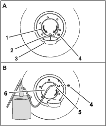
-
Place a drain pan under the oil port of the wheel hub (Figure 94).
-
Remove the plug and drain the oil from the planetary (Figure 94).
-
Check the condition of the O-ring for the plug.
Note: Replace the plug if the O-ring is worn or damaged.
-
Move the machine forward or backward until the plug is either at the 2 o’clock (Figure 94) or the 10 o’clock position.
-
Add the specified oil to the wheel hub through the oil port until the oil level is at the bottom of the threads of the port.
-
Install the plug in the oil port of the wheel hub.
-
Repeat this procedure for the other wheel hubs.
Checking the Oil Level in the Axles
| Maintenance Service Interval | Maintenance Procedure |
|---|---|
| After the first 100 hours |
|
| Every 400 hours |
|
-
Place a drain pan under the differential housing of the axle.
-
Remove the plugs from the sight port in the differential housing of the axle (Figure 95 and Figure 96).
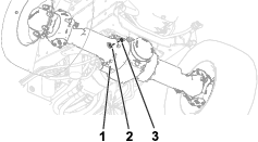
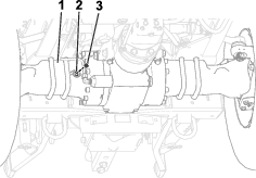
-
Look through the sight port and check that the oil level in the axle is level with the bottom of the threads of the port (Figure 95 and Figure 96).
Note: Use a flashlight and a mirror to help you see the oil level.
-
If the oil level is too high, allow the oil to drain from the sight port.
-
If the oil level is too low, add the specified oil to the axle housing sight port; refer to steps 6 and 7 in Changing the Oil in the Axles.
-
-
Clean the threads of the sight plug.
-
Apply PTFE thread sealing tape to the threads of the plug.
-
Install the sight plug into the sight port in the differential housing of the axle (Figure 95 and Figure 96).
Changing the Oil in the Axles
| Maintenance Service Interval | Maintenance Procedure |
|---|---|
| After the first 150 hours |
|
| Every 1,000 hours |
|
| Every 1,500 hours |
|
Axle oil capacity: approximately 9 L (9.5 US qt)
-
Place a drain pan under the differential housing of the axle (Figure 97 and Figure 98).
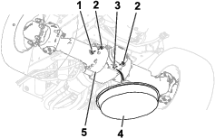
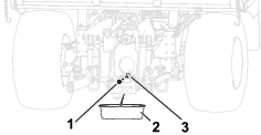
-
Remove the plugs from the sight port and the drain port of the differential housings for the axles (Figure 97 and Figure 98).
Note: Allow the oil to drain completely from the differential housing and axle.
Note: Refer to Figure 96 for the rear-axle sight port.
-
Clean the threads of the plugs.
-
Apply PTFE thread sealing tape to the threads of the plugs.
-
Install the drain plugs into the drain ports at the differential housings (Figure 99 and Figure 100).
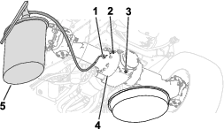
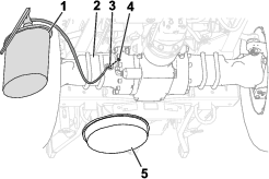
-
Fill the axles with the specified oil through the sight port until the oil is level with the threads at the bottom of the port (Figure 99 and Figure 100).
-
Wait a few minutes for the oil to settle, then add more oil as necessary.
Note: Continue to add oil until the oil level stabilizes and is at the bottom of the threads of the sight port.
-
Install the fill plugs into the sight ports of the differential housings for the axles (Figure 99 and Figure 100).
Cleaning the Axle Breathers
| Maintenance Service Interval | Maintenance Procedure |
|---|---|
| After the first 200 hours |
|
| Every 400 hours |
|
-
Clean the area around the breathers with a cleaning solvent (Figure 101 and Figure 102).
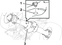
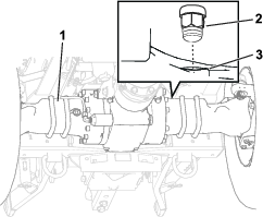
-
Remove the breathers from the front axle and rear axles (Figure 101 and Figure 102).
-
Clean the breathers with a cleaning solvent.
-
Use compressed air to dry the breathers.
Important: Wear face protection when using compressed air.
-
Install the breathers into the front and rear axles (Figure 101 and Figure 102).
Changing the Hydraulic-Brake Oil
| Maintenance Service Interval | Maintenance Procedure |
|---|---|
| After the first 150 hours |
|
| Every 1,000 hours |
|
| Every 1,500 hours |
|
Note: The hydraulic brake is adjacent to the rear axle.
Hydraulic-brake oil specification: Toro Premium Tractor Fluid
-
Place a drain pan under the hydraulic brake (Figure 103).
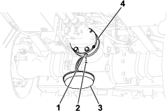
-
Remove the drain plug from the drain port (Figure 103).
Note: Allow the oil to drain completely from the brake housing.
-
Clean the threads of the plug.
-
Install the drain plug into the drain port (Figure 103).
-
Remove the fill plug at the top of the brake housing (Figure 104).
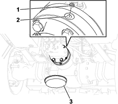
-
Fill the brake housing with 160 ml (5.4 fl oz) of the specified oil through the fill port.
-
Install the fill plug into the fill port (Figure 104).
Changing the Rear-PTO-Gearbox Oil
| Maintenance Service Interval | Maintenance Procedure |
|---|---|
| After the first 150 hours |
|
| Every 1,000 hours |
|
| Every 1,500 hours |
|
Rear-PTO-gearbox oil specification: Toro Premium Tractor Fluid
-
Remove the standard bed (if equipped) from the machine; refer to Removing or Installing the Standard Bed.
-
Remove the plug from the sight port of the rear PTO gearbox (Figure 105).
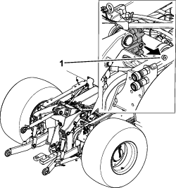
-
Remove the plug from the drain port (Figure 106).
Note: Allow the oil to drain completely from the gearbox.
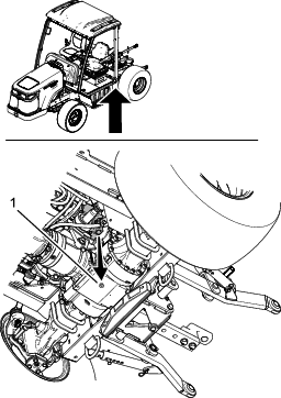
-
Clean the threads of the plug.
-
Install the drain plug into the drain port.
-
Fill the gearbox with 1.4 L (48 fl oz) the specified oil through the sight port until the oil is level with the threads at the bottom of the port.
-
Wait a few minutes for the oil to settle, then add more oil as necessary.
Note: Continue to add oil until the oil level stabilizes and is at the bottom of the threads of the sight port.
-
Install the sight plug into the sight port.
Torquing the Wheel Lug Nuts
| Maintenance Service Interval | Maintenance Procedure |
|---|---|
| After the first hour |
|
| After the first 10 hours |
|
| Every 400 hours |
|
Wheel lug nut torque specification: 380 to 433 N∙m (280 to 320 ft-lb)
Torque the wheel lug nuts in a crossing pattern as shown in Figure 107 to the specified torque.
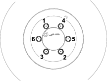
Cooling System Maintenance
Cooling System Safety
-
Shut off the engine and remove the key before performing maintenance.
-
Swallowing engine coolant can cause poisoning; keep out of reach from children and pets.
-
Discharge of hot, pressurized coolant or touching a hot radiator and surrounding parts can cause severe burns.
-
Always allow the engine to cool at least 15 minutes before removing the radiator cap.
-
Use a rag when opening the radiator cap, and open the cap slowly to allow steam to escape.
-
-
Do not operate the machine without the covers in place.
-
Keep your fingers, hands and clothing clear of rotating fan and drive belt.
Checking the Cooling System
| Maintenance Service Interval | Maintenance Procedure |
|---|---|
| Before each use or daily |
|
Check the coolant level at the beginning of each day. The capacity of the system is 8.5 L (9 US qt).
-
Raise the hood; refer to Raising the Hood.
-
Carefully remove the radiator cap and expansion-tank cap (Figure 108).
-
Check the coolant level in the radiator.
Note: The radiator should be filled to the top of the filler neck and the expansion tank filled to the Full mark.
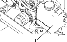
-
If the coolant is low, add a 50/50 mixture of water and ethylene glycol anti-freeze.
Important: Do not use water only or alcohol/methanol-based coolants, as this may cause damage.
-
Install the radiator cap and expansion-tank cap.
Servicing the Engine-Cooling System
| Maintenance Service Interval | Maintenance Procedure |
|---|---|
| Before each use or daily |
|
| Every 100 hours |
|
| Every 2 years |
|
Remove debris from the radiator/fuel cooler daily. Clean them more frequently in dirty conditions.
-
Raise the hood; refer to Raising the Hood.
-
Lower the front screen by releasing the strap that holds it in place (Figure 109).
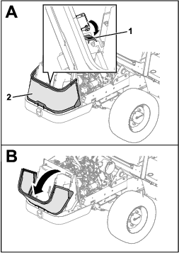
-
Clean the radiator/fuel cooler area thoroughly with compressed air (Figure 110).
Note: Start from the fan side and blow the debris out toward the back. Then, clean from the back side and blow toward the front. Repeat this procedure several times until all chaff and debris is removed.
Important: Do not clean the radiator/fuel cooler area with water; doing so can promote a plugged system, premature corrosion, and damage to components.
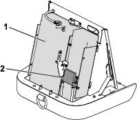
-
Close the hood.
Hydraulic System Maintenance
Hydraulic System Safety
-
Seek immediate medical attention if fluid is injected into skin. Injected fluid must be surgically removed within a few hours by a doctor.
-
Ensure that all hydraulic-fluid hoses and lines are in good condition and all hydraulic connections and fittings are tight before applying pressure to the hydraulic system.
-
Keep your body and hands away from pinhole leaks or nozzles that eject high-pressure hydraulic fluid.
-
Use cardboard or paper to find hydraulic leaks.
-
Safely relieve all pressure in the hydraulic system before performing any work on the hydraulic system.
Hydraulic Fluid Specifications
The reservoir is filled at the factory with approximately 44 L (11.75 US gallons) of high-quality hydraulic fluid. Check the level of the hydraulic fluid before the engine is first started and daily thereafter; refer to Checking the Hydraulic-Fluid Level.
Recommended replacement fluid: Toro Premium Transmission/Hydraulic Tractor Fluid; available in 19 L (5 US gallon) pails or 208 L (55 US gallon) drums.
Alternative fluids: If Toro Premium Tractor Fluid is not available, you may use other conventional, petroleum-based Universal Tractor Hydraulic Fluids (UTHF), provided that its specifications fall within the listed range for all the following material properties and that it meets industry standards. We do not recommend the use of synthetic fluid. Consult with your lubricant distributor to identify a satisfactory product.
Note: Toro does not assume responsibility for damage caused by improper substitutions, so use products only from reputable manufacturers who will stand behind their recommendation.
| Material Properties: | ||
| Viscosity, ASTM D445 | cSt @ 40° C 55 to 62 | |
| Viscosity Index ASTM D2270 | 140 - 152 | |
| Pour Point, ASTM D97 | -35° F to -46° F | |
| Industry Specifications: | API GL-4, Vickers 35VQ25 | |
Note: Many hydraulic fluids are almost colorless, making it difficult to spot leaks. A red dye additive for the hydraulic fluid is available in 20 ml (2/3 fl oz) bottles. A bottle is sufficient for 15 to 22 L (4 to 6 US gallons) of hydraulic fluid. Order Part No. 44-2500 from your authorized Toro distributor.
Checking the Hydraulic-Fluid Level
| Maintenance Service Interval | Maintenance Procedure |
|---|---|
| Before each use or daily |
|
-
Park the machine on a level surface.
-
Disengage the PTO, move the shift lever to the NEUTRAL position, lower all attachments (if equipped), engage the parking brake, shut off the engine, and remove the key.
-
Remove the plug from the hydraulic tank (Figure 111).
Note: The hydraulic-tank plug and dipstick are located behind the passenger-side seat.
-
Remove the dipstick from the hydraulic tank and wipe it with a clean cloth (Figure 111).
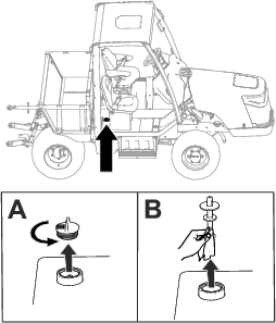
-
Insert the dipstick into the hydraulic tank.
-
Remove the dipstick and check the fluid level (Figure 112).
The hydraulic-fluid level is at the appropriate level when the fluid appears between the 2 marks on the dipstick.
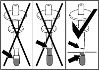
-
If the fluid level is below the lower mark on the dipstick, add the specified hydraulic fluid into the tank (Figure 113). Repeat steps 4 through 6 until the fluid level appears between the 2 marks on the dipstick.
Important: Do not overfill the hydraulic tank with fluid. The tank is overfilled when the fluid appears above the upper mark on the dipstick.
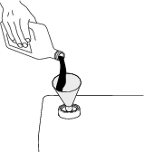
-
Insert the dipstick and plug into the hydraulic tank
-
Check all hydraulic hoses and fittings for leaks.
Changing the Hydraulic Fluid and Filters
| Maintenance Service Interval | Maintenance Procedure |
|---|---|
| After the first 1000 hours |
|
| Every 1,500 hours |
|
If the hydraulic fluid becomes contaminated, contact your authorized Toro distributor; the system must be flushed. Contaminated fluid looks milky or black when compared to clean fluid.
Important: Use Toro replacement filters; refer to the machine Parts Catalog. Using any other filter may void the warranty on some components.
-
Park the machine on a level surface.
-
Disengage the PTO, move the shift lever to the NEUTRAL position, lower all attachments (if equipped), engage the parking brake, shut off the engine, and remove the key.
-
Place a large drain pan under the hydraulic-fluid tank.
-
Remove the hydraulic-tank cap and dipstick.
-
Remove the drain plug from the bottom of the tank and let the hydraulic fluid flow into the pan (Figure 114).
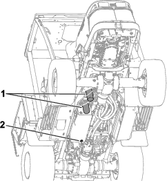
-
Install the drain plug when the hydraulic fluid stops draining.
-
Clean the area around the filter-mounting areas.
-
Place a drain pan under the filter and remove the filter (Figure 114).
-
Lubricate the new filter gasket and fill the filter with hydraulic fluid.
-
Ensure that each filter-mounting area is clean and screw the filter on until the gasket contacts the mounting plate; then tighten the filter an additional 1/2 turn.
-
Fill the reservoir with hydraulic fluid; refer to Checking the Hydraulic-Fluid Level.
Important: Use only the hydraulic fluids specified. Other fluids could cause system damage.
-
Install the reservoir dipstick and cap.
-
Start the engine and use all of the hydraulic controls to distribute hydraulic fluid throughout the system.
Note: Also, check for leaks, then shut off the engine.
-
Check the fluid level and add enough to raise the level to the Full mark on the dipstick.
Note: Do not overfill.
Checking the Hydraulic Lines and Hoses
| Maintenance Service Interval | Maintenance Procedure |
|---|---|
| Every 2 years |
|
Inspect the hydraulic lines and hoses daily for leaks, kinked lines, loose mounting supports, wear, loose fittings, weather deterioration, and chemical deterioration. Make all necessary repairs before operating the machine.
Cab Maintenance
Cleaning the Cab
Important: Use care around the cab seals (Figure 115). If you are using a pressure washer, keep the washer wand at least 0.6 m (2 ft) away from the machine. Do not use the pressure washer directly on the cab seals or under the rear overhang.
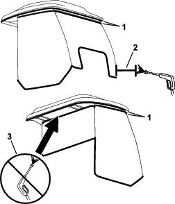
Cleaning the Cab Air Filters
| Maintenance Service Interval | Maintenance Procedure |
|---|---|
| Every 400 hours |
|
-
Remove the knobs and grates from the cab rear overhang (Figure 116).
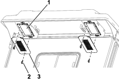
-
Remove the air filters from the cab.
-
Clean the filters by blowing clean, oil-free, compressed air through them.
Important: If either filter has a hole, tear, or other damage, replace the filter.
-
Use the knobs and grates to install the filters into the cab (Figure 116).
Cleaning the Cab Condenser Filter
The purpose of the cab condenser filter is to prevent large debris, such as grass and leaves, from entering the cab condenser and condenser fans.
-
Pull the screen cover straight down.
-
Clean the condenser filter with water.
Note: Do not use a pressure washer.
Important: If the filter has a hole, tear, or other damage, replace the filter.
-
Allow the filter to dry before installing it into the machine.
-
Rotate the filter screen around the tabs until the latch locks into the latch-mount assembly (Figure 117).
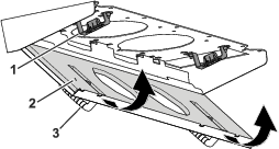
Replacing the Dome Light
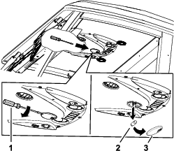
Filling the Windshield-Wiper-Fluid Reservoir
Note: The windshield-wiper-fluid reservoir is located behind the passenger seat.
-
Remove the cap on the reservoir (Figure 119).
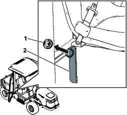
-
Fill the reservoir with wiper fluid.
-
Replace the cap on the reservoir
Storage
Preparing the Machine for Storage
Preparing the Traction Unit
-
Remove any equipped attachments.
-
Move the shift lever to the NEUTRAL position, lower any equipped attachments, shut off the engine, and remove the key. Wait for all movement to stop and allow the machine to cool.
-
Thoroughly clean the traction unit and the engine.
Important: Do not use high-pressure water near the dashboard or rubber cab seals, as this may cause damage.
Important: Do not use brackish or reclaimed water to clean the machine.
-
Check the tire pressure; refer to Checking the Tire Air Pressure.
-
Check all fasteners for looseness; tighten as necessary.
-
Grease or oil all grease fittings and pivot points and wipe up any excess lubricant; refer to Greasing the Bearings and Bushings.
-
Lightly sand and use touch-up paint on painted areas that are scratched, chipped, or rusted, and repair any dents in the metal body.
-
Service the battery and cables as follows:
-
Remove the battery terminals from the battery posts; refer to Disconnecting the Battery.
-
Clean the battery, terminals, and posts with a wire brush and baking-soda solution.
-
Coat the cable terminals and battery posts with Grafo 112X skin-over grease (Toro Part No. 505-47) to prevent corrosion.
-
Slowly charge the battery every 60 days for 24 hours to prevent lead sulfation of the battery.
-
Preparing the Engine
-
Drain the engine oil from the oil pan and install the drain plug; refer to Changing the Engine Oil and Filter.
-
Remove the existing oil filter and install a new oil filter; refer to Changing the Engine Oil and Filter.
-
Fill engine with oil; refer to Servicing the Engine Oil.
-
Start the engine and run it at idle speed for approximately 2 minutes.
-
Remove the key and shut off the fuel (if equipped) before storing or transporting the machine.
-
Flush the fuel tank with fresh, clean fuel.
-
Secure all of the fuel-system fittings.
-
Thoroughly clean and service the air-cleaner assembly; refer to Servicing the Air Cleaner.
-
Seal the air-cleaner inlet and the exhaust outlet with weatherproof tape.
-
Check the anti-freeze protection and add a 50/50 solution of water and ethylene glycol anti-freeze as needed for the expected minimum temperature in your area.