Warning
CALIFORNIA
Proposition 65 Warning
Use of this product may cause exposure to chemicals known to the State of California to cause cancer, birth defects, or other reproductive harm.
Safety
Safety and Instructional Decals
 |
Safety decals and instructions are easily visible to the operator and are located near any area of potential danger. |

Installation
Removing the Hydraulic Motor
-
Park the machine on a level surface, lower the mower deck, engage the parking brake, shut off the engine, and remove the key.
-
Ensure that the traction pedal is in the NEUTRAL position and the PTO lever is in the OFF position.
-
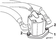
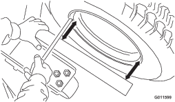
Remove the bolts securing the hydraulic motor to the deck (Figure 1).
-
Lift the motor off the deck and lay it on a clean surface out of the way.
Note: Ensure that you do not damage aluminum coupler.
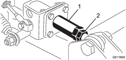
-
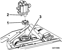
Remove the elastomeric spider from inside the pulley coupler. Inspect it for wear and replace it if it is worn. Otherwise, retain it to install on the new deck (Figure 2).
Note: Inspect the spider hub for wear and replace it if it is worn (Figure 2).
Replacing the Side Mower Deck
-
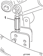
Remove the hairpin cotter and clevis pin securing the height-of-cut link to the height-of-cut bracket on the deck (Figure 3).
-
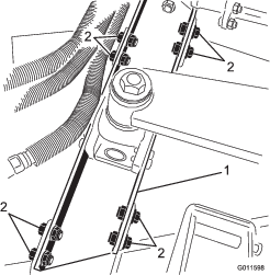
Remove the 8 bolts, washers, and locknuts securing the lift-arm mount to the mower-deck brackets (Figure 4).
-
Move the mower deck away from the traction unit.
-
Slide the new mower deck into position and mount it to the traction unit by reversing this procedure.
-
Check the deck alignment to the traction unit as follows:
-
Make sure that the machine is on a level, hard surface.
-
Place a square or straight edge against the deck weldment that contains the castor-fork assembly (Figure 5). Do not use the caster-fork assembly itself.
-
Measure from the inset bead of the rim (not the outer edge of the rim) to the straight edge at 2 locations as indicated in Figure 5. Rim and paint irregularities make the outer edge an unreliable point of measure. These 2 measurements should be within 3 mm (1/8 inch) of each other.
-
If the deck is not aligned with the traction unit, loosen the jam nut on the rod end of the wing-deck shock-arm assembly (Figure 6). Adjust the coupler so that it freely rotates inside the shock-absorption tube. Make all adjustments with the rod end of the shock arm bolted to the deck.
-
Raise and lower the deck and check the dimensions for correct alignment. Tighten the jam nut to 155 N•m (114 ft-lb) on the shock-arm assembly.
Note: Because of differences in grass conditions and the counterbalance setting of the traction unit, cut the grass and check its appearance before mowing the entire lawn. Refer to the traction unit Operator's Manual for deck leveling procedures.
-