Installation
Preparing the Machine
-
Park the machine on a level surface.
-
Shut off the engine, engage the parking brake, and remove the key from the ignition switch.
-
Disconnect the battery; refer to the electrical system maintenance section of your Operator’s Manual.
Removing the Sunshade
Preparing the Switch Panel
Parts needed for this procedure:
| Decal | 1 |
| Switch panel | 1 |
Installing the Decal to the Switch Panel
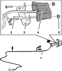
Assembling the Wire Harness to the Switch Panel
Parts needed for this procedure:
| Fuse-block mount | 1 |
| Wire harness | 1 |
| Socket-head screw (#10 x 3/4 inch) | 2 |
| Flange locknut (#10) | 4 |
| Carriage bolt (#10 x 1/2 inch) | 2 |
Assembling the Fuse-Block Mount to the Wire Harness
-
Align the holes in the fuse-block mount to the holes in the fuse block of the wire harness as shown in Figure 5.
Note: Ensure that the mounting rails of the fuse block are aligned up.
-
Assemble the fuse-block mount to the fuse block (Figure 5) with the 2 socket-head screws (#10 x 3/4 inch) and 2 flange locknuts (#10).
-
Torque the socket-head screws and flange-locknuts to 419 to 513 N∙cm (37 to 47 in-lb).
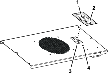
Assembling the Wire Harness to the Switch Panel
-
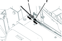
Align the wire harness to the switch panel (Figure 6).
-
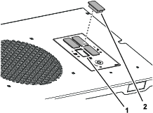
Align the mounting rails of the fuse block up and insert the fuse block into the rectangular opening in the switch panel as shown in Figure 7.
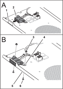
-
Align the square holes in the fuse-block mount with the square holes in the switch panel (Figure 7).
-
Assemble the fuse-block mount to the switch panel (Figure 7) with the 4 carriage bolts (#10 x 1/2 inch) and 4 flange locknut (#10).
-
Torque the flange-locknuts to 419 to 513 N∙cm (37 to 47 in-lb).
Installing the Switch Panel to the Sunshade Frame
Parts needed for this procedure:
| Carriage bolt (#10 x 1/2 inch) | 4 |
| Flange locknut (#10) | 4 |
| Cable tie | 6 |
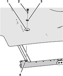
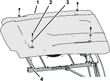
Assembling the Switch Panel to the Sunshade Frame
-
Align the square holes in the switch panel with the square holes in the 2 side-frame channels of the sunshade as shown in Figure 8.
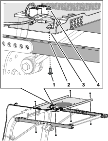
-
Assemble the switch panel to the side-frame channels (Figure 8) with the 4 carriage bolts (#10 x 1/2 inch) and 4 flange locknut (#10).
-
Torque the flange-locknuts to 419 to 513 N∙cm (37 to 47 in-lb).
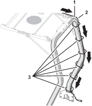
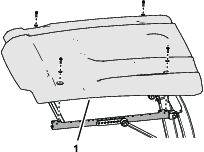
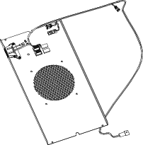
Installing the Sunshade
-
Align the holes in the grommets of the sunshade with the 4 clipnuts of the side-frame channels.
-
Assemble the sunshade to the frame channels (Figure 10) with the 4 flange-head bolts (5/16 x 1-1/4 inches) and 4 washers (5/16 inch) that you removed in Removing the Sunshade.
-
Torque the flange-head bolts to 1017 to 1355 N∙cm (90 to 120 in-lb).
Connecting the Wire Harness
Connecting the Wire Harness to the Chassis Harness
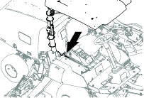
-
For Groundsmaster 5900 machines, raise the hood; refer to the Operator’s Manual for your machine.
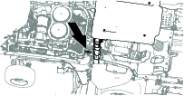
-
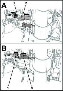
If installed, remove the cap from the 2-socket connector of the machine wire harness (Figure 13).
-
Connect the 2-pin connector of the wire harness of the kit to the 2-socket connector of the machine wire harness (Figure 13 or Figure 14).
-
For Groundsmaster 5900 machines, lower the hood; refer to the Operator’s Manual for your machine.
Connecting the Wire Harness to the Optional Power Harness Kit
Connect the 2-pin connector of the wire harness of the kit to the 2-socket connector of the optional power harness; refer to the Installation Instructions for the power harness kit.
Connecting the Battery
Connect the battery; refer to the electrical system maintenance section of your Operator’s Manual.