| Maintenance Service Interval | Maintenance Procedure |
|---|---|
| Before each use or daily |
|
Introduction
This machine is a ride-on, rotary-blade lawnmower intended to be used by professional, hired operators in commercial applications. It is primarily designed for cutting grass on well-maintained lawns in parks, golf courses, sports fields, and on commercial grounds. It is not designed for cutting brush, mowing grass and other growth alongside highways, or for agricultural uses.
Read this information carefully to learn how to operate and maintain your product properly and to avoid injury and product damage. You are responsible for operating the product properly and safely.
You may contact Toro directly at www.Toro.com for product and accessory information, help finding a dealer, or to register your product.
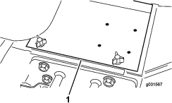
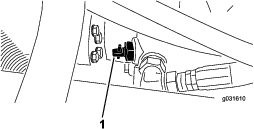
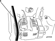
Whenever you need service, genuine Toro parts, or additional information, contact an Authorized Service Dealer or Toro Customer Service and have the model and serial numbers of your product ready. Figure 1 identifies the location of the model and serial numbers on the product. Write the numbers in the space provided.
This manual identifies potential hazards and has safety messages identified by the safety-alert symbol (Figure 2), which signals a hazard that may cause serious injury or death if you do not follow the recommended precautions.

This manual uses 2 words to highlight information. Important calls attention to special mechanical information and Note emphasizes general information worthy of special attention.
This product complies with all relevant European directives; for details, please see the separate product specific Declaration of Conformity (DOC) sheet.
It is a violation of California Public Resource Code Section 4442 or 4443 to use or operate the engine on any forest-covered, brush-covered, or grass-covered land unless the engine is equipped with a spark arrester, as defined in Section 4442, maintained in effective working order or the engine is constructed, equipped, and maintained for the prevention of fire.
The enclosed engine owner's manual is supplied for information regarding the US Environmental Protection Agency (EPA) and the California Emission Control Regulation of emission systems, maintenance, and warranty. Replacements may be ordered through the engine manufacturer.
Warning
CALIFORNIA
Proposition 65 Warning
Diesel engine exhaust and some of its constituents are known to the State of California to cause cancer, birth defects, and other reproductive harm.
Battery posts, terminals, and related accessories contain lead and lead compounds, chemicals known to the State of California to cause cancer and reproductive harm. Wash hands after handling.
Use of this product may cause exposure to chemicals known to the State of California to cause cancer, birth defects, or other reproductive harm.
Safety
This machine has been designed in accordance with EN ISO 5395:2013 and ANSI B71.4-2012.
General Safety
This product is capable of amputating hands and feet and of throwing objects. Always follow all safety instructions to avoid serious personal injury.
Using this product for purposes other than its intended use could prove dangerous to you and bystanders.
-
Read and understand the contents of this Operator’s Manual before you start the engine. Ensure that everyone using this product knows how to use it and understands the warnings.
-
Do not put your hands or feet near moving components of the machine.
-
Do not operate the machine without all guards and other safety protective devices in place and working on the machine.
-
Keep clear of any discharge opening. Keep bystanders a safe distance from the machine.
-
Keep children out of the operating area. Never allow children to operate the machine.
-
Stop the machine and shut off the engine before servicing, fueling, or unclogging the machine.
Improperly using or maintaining the machine can result in injury. To reduce the potential for injury, comply with these safety instructions and always pay attention to the safety-alert symbol, which means Caution, Warning, or Danger—personal safety instruction. Failure to comply with these instructions may result in personal injury or death.
You can find additional items of safety information in their respective sections throughout this manual.
Sound Power Level
This unit has a guaranteed sound power level of 104 dBA, which includes an Uncertainty Value (K) of 1 dBA.
Sound power level was determined according to the procedures outlined in ISO 11094.
Sound Pressure Level
This unit has a sound pressure level at the operator’s ear of 90 dBA, which includes an Uncertainty Value (K) of 1 dBA.
Sound pressure level was determined according to the procedures outlined in EN ISO 5395:2013.
Caution
Long-term exposure to noise while operating the machine may cause some hearing loss.
Wear adequate hearing protection whenever you operate the machine for an extended period of time.
Vibration Level
Hand-Arm
Measured vibration level for right hand = 0.5 m/s2
Measured vibration level for left hand = 0.7 m/s2
Uncertainty Value (K) = 0.5 m/s2
Measured values were determined according to the procedures outlined in EN ISO 5395:2013.
Whole Body
Measured vibration level = 0.44 m/s2
Uncertainty Value (K) = 0.5 m/s2
Measured values were determined according to the procedures outlined in EN ISO 5395:2013.
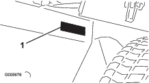
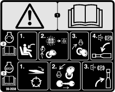
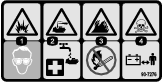
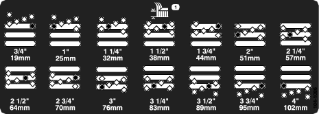
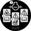
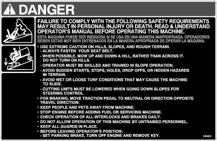
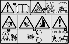
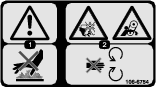
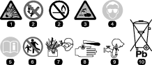
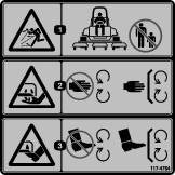
Safety and Instructional Decals
 |
Safety decals and instructions are easily visible to the operator and are located near any area of potential danger. Replace any decal that is damaged or lost. |


Setup
Note: Determine the left and right sides of the machine from the normal operating position.
Activating, Charging, and Connecting the Battery
Warning
Battery posts, terminals, and related accessories contain lead and lead compounds, chemicals known to the State of California to cause cancer and reproductive harm. Wash hands after handling.
Note: If the battery is not filled with electrolyte or activated, purchase bulk electrolyte with 1.26 specific gravity from a local battery-supply outlet and add it to the battery.
Danger
Battery electrolyte contains sulfuric acid which is a deadly poison and causes severe burns.
-
Do not drink electrolyte and avoid contact with skin, eyes, or clothing. Wear safety glasses to shield your eyes and rubber gloves to protect your hands.
-
Fill the battery where clean water is always available for flushing the skin.
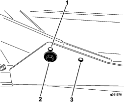
-
Remove the battery cover (Figure 3).
-
Remove the filler caps from the battery and slowly fill each cell until the electrolyte is just above the plates.
-
Install the filler caps and connect a 3 to 4 A battery charger to the battery posts.
Note: Charge the battery at a rate of 3 to 4 A for 4 to 8 hours.
Warning
Charging the battery produces gasses that can explode.
-
Keep sparks and flames away from battery.
-
Never smoke near the battery.
-
-
When the battery is charged, disconnect the charger from the electrical outlet and battery posts.
-
Remove the filler caps.
-
Slowly add electrolyte to each cell until the level is up to the fill ring.
Important: Do not overfill the battery. Electrolyte will overflow onto other parts of the machine and severe corrosion and deterioration will result.
-
Install the filler caps.
-
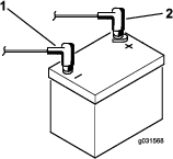
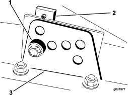
Install the positive cable (red) to the positive (+) terminal and the negative cable (black) to the negative (–) terminal of the battery and secure them with the bolts and nuts (Figure 4).
Note: Ensure that the positive (+) terminal is all the way onto the post and the cable is positioned snug to the battery. The cable must not contact the battery cover.
Warning
Incorrect battery cable routing could damage the tractor and cables, causing sparks. Sparks can cause the battery gases to explode, resulting in personal injury.
-
Always disconnect the negative (black) battery cable before disconnecting the positive (red) cable.
-
Always connect the positive (red) battery cable before connecting the negative (black) cable.
Important: If you ever remove the battery, install that the battery-clamp bolts with the bolt heads positioned on the bottom side and the nuts on the top side. If the clamp bolts are reversed, they may interfere with the hydraulic tubes when shifting the cutting units.
-
-
Coat both battery connections with Grafo 112X (skin over) grease (Toro Part No. 505-47), petroleum jelly, or light grease to prevent corrosion.
-
Slide the rubber boot over the positive terminal to prevent a possible short from occurring.
-
Install the battery cover.
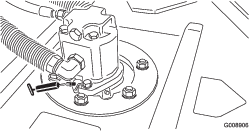
Checking the Angle Indicator
Models 30807, 30839, and 30843 Only
Parts needed for this procedure:
| Inclinometer | 1 |
-
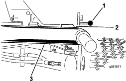
Park the machine on a flat, level surface.
-
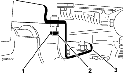
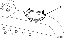
Verify that the machine is level by placing a handheld inclinometer (supplied with the machine) on the frame cross rail, by the fuel tank (Figure 5).
Note: The inclinometer should read at 0° when viewed from the operating position.
-
If the inclinometer does not read 0°, move the machine to a different location to obtain a 0° reading.
Note: The angle indicator, mounted on the machine, should now read 0° also.
-
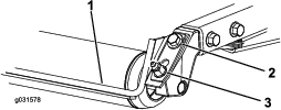
If the angle indicator does not read 0°, loosen the 2 screws and nuts securing the angle indicator to the mounting bracket, adjust the indicator to obtain a 0° reading, and tighten the bolts.
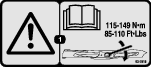
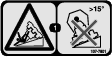
Installing the CE Decals
Parts needed for this procedure:
| Warning decal (104-5181) | 1 |
| Warning decal (99-3558) | 1 |
| Warning decal (107-1972) | 3 |
If this machine will be used for CE, affix the CE-warning decals over the corresponding English warning decals.
Installing the Hood Latch
CE Only
Parts needed for this procedure:
| Lock bracket | 1 |
| Rivet | 2 |
| Washer | 1 |
| Screw (1/4 x 2 inches) | 1 |
| Locknut (1/4 inch) | 1 |
-
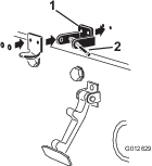
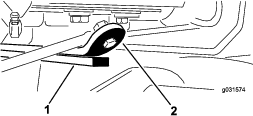
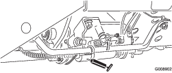
Unhook the hood latch from the hood-latch bracket.
-
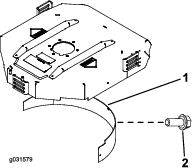
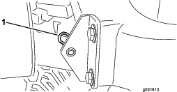
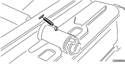
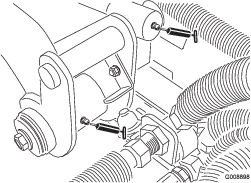
Remove the 2 rivets securing the hood-latch bracket to the hood (Figure 6).
-
Remove the hood-latch bracket from the hood.
-
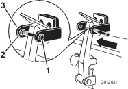
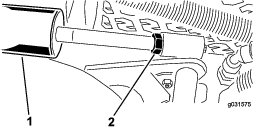
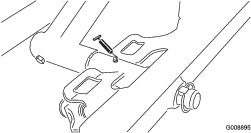
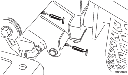
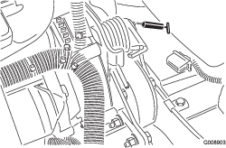
While aligning the mounting holes, position the lock bracket and the hood-latch bracket onto the hood (Figure 7).
Note: The lock bracket must be against the hood.
Note: Do not remove the bolt and nut from the lock-bracket arm.
-
Align the washers with the holes on the inside of the hood.
-
Rivet the brackets and the washers to the hood (Figure 7).
-
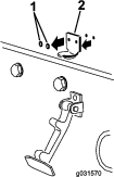
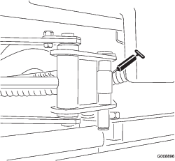
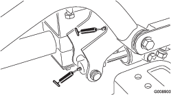
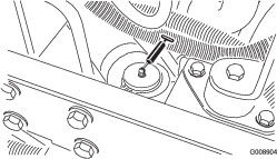
Hook the latch onto the hood-latch bracket (Figure 8).
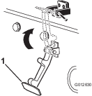
-
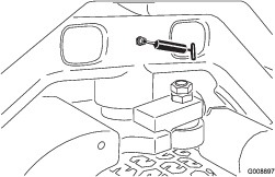
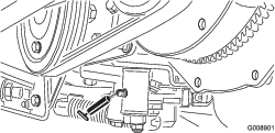
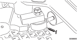
Install the bolt into the other arm of the hood-lock bracket to lock the latch in position (Figure 9).
Note: Tighten the bolt securely, but do not tighten the nut.
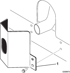
Installing the Exhaust Guard
Adjusting the Lift Arms
-
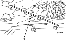
Start the engine, raise the cutting units, and ensure that the clearance between each lift arm and the floor-plate bracket is 5 to 8 mm (0.18 to 0.32 inches) as shown in Figure 11.
If the clearance is not in this range, adjust it as follows:
-
Ensure that the clearance between each lift arm and stop bolt is 0.13 to 1.02 mm (0.005 to 0.040 inches) as shown in Figure 12.
Note: If the clearance is not in this range, adjust the stop bolts to attain the proper clearance.
-
Start the engine, raise the cutting units, and ensure that the clearance between the wear strap on the top of the rear-cutting-unit wear bar and the bumper strap is 0.51 to 2.54 mm (0.02 to 0.10 inches) as shown in Figure 14.
If the clearance is not in this range, adjust the rear cylinder as follows:
Note: If the rear-lift arm clunks during transport, you can reduce clearance.
-
Lower the cutting units and back off the jam nut on the cylinder (Figure 15).
-
Grasp the cylinder rod close to the nut with a pliers and rag, and rotate the rod.
-
Raise the cutting units and check the clearance.
Note: Repeat the procedure if required.
-
Tighten the clevis jam nut.
-
Important: Lack of clearance at the front stops or rear wear bar could damage the lift arms.
Adjusting the Carrier Frame
Adjusting the Front Cutting Decks
The front and rear cutting decks require different mounting positions. The front cutting deck has 2 mounting positions depending on what height of cut and degree of deck rotation you desire.
-
For heights of cut in the 2 to 7.6 cm (3/4 to 3 inches) range, mount the front carrier frames in the lower, front mounting holes (Figure 16).
Note: This permits more up travel of the cutting decks relative to the machine when approaching sudden changes in uphill terrain. It does, however, limit the clearance of the chamber to the carrier when cresting sharp, small hills.
-
For heights of cut in the 6.3 to 10 cm (2-1/2 to 4 inches) range, mount the front carrier frames in the upper, front mounting holes (Figure 16).
Note: This increases the chamber to carrier clearance due to the higher position of the cutting chamber, but causes the cutting deck to reach its maximum up travel more quickly.
Adjusting the Rear Cutting Deck
The front and rear cutting decks require different mounting positions. The rear cutting deck has 1 mounting position for proper alignment with the sidewinder under frame.
For all heights of cut, mount the rear cutting deck in the rear mounting holes (Figure 16).
Adjusting the Height of Cut
Important: This cutting deck often cuts approximately 6 mm (1/4 inch) lower than a reel cutting unit with the same bench setting. It may be necessary to have the rotary cutting decks bench set 6 mm (1/4 inch) above that of the reels cutting in the same area.
Important: Access to the rear cutting units is greatly improved by removing the cutting unit from the machine. If the machine is equipped with a Sidewinder® unit, side-wind the cutting units to the right, remove the rear cutting unit, and slide it out to the right side.
-
Lower the cutting deck to the ground, shut off the engine, and remove the ignition key.
-
Loosen the bolt securing each height-of-cut bracket to the height-of-cut plate (front and each side) as shown in Figure 17.
-
Beginning with the front adjustment, remove the bolt.
-
While supporting the chamber, remove the spacer (Figure 17).
-
Move the chamber to the desired height of cut and install a spacer into the designated height-of-cut hole and slot (Figure 18).

-
Position the tapped plate in line with the spacer.
-
Install the bolt (finger tight).
-
Repeat steps 4 to 7 for each side adjustment.
-
Tighten the 3 bolts to 41 N∙m (30 ft-lb).
Note: Tighten the front bolt first.
Note: Adjustments of more than 3.8 cm (1-1/2 inches) may require temporary assembly to an intermediate height to prevent binding (e.g., changing from 3.1 to 7 cm (1-1/4 to 2-3/4 inches) height of cut).
Adjusting the Roller Scraper
Optional
The optional rear roller scraper works best when there is an even gap of 0.5 to 1 mm (0.02 to 0.04 inch) between the scraper and the roller.
-
Loosen the grease fitting and the mounting screw (Figure 19).
-
Slide the scraper up or down until you obtain a gap of 0.5 to 1 mm (0.02 to 0.04 inch) between the rod and the roller.
-
Tighten the grease fitting and screw to 41 N∙m (30 ft-lb) in an alternating sequence.
Installing the Mulching Baffle
Optional
-
Thoroughly clean debris from the mounting holes on the rear wall and left wall of the chamber.
-
Install the mulching baffle in the rear opening and secure it with 5 flange-head bolts (Figure 20).
-
Verify that mulching baffle does not interfere with the tip of the blade and does not protrude inside the surface of the rear chamber wall.
Product Overview
Traction Pedals
Press the forward traction pedal to move forward. Press reverse traction pedal to move backward or to assist in stopping when moving forward (Figure 21).
Note: Allow the pedal to move or move it to the NEUTRAL position to stop the machine.
Mow/Transport Slide
Using your heel, move the mow/transport slide to the left to transport, and to the right to mow (Figure 21).
Note: The cutting units operate only in the mow position.
Important: The mow speed is set at the factory to 9.7 km/h (6 mph). You can increase or decrease the mow speed by adjusting the speed-stop screw (Figure 22).
Tilt-Steering Lever
Pull the tilt-steering lever back to tilt the steering wheel to the desired position, then push the lever forward to tighten (Figure 21).
Indicator Slot
Models 30807, 30839, and 30849 Only
The indicator slot in the operator platform indicates when the cutting units are in the center position (Figure 21) .
Angle Indicator
Models 30807, 30839, and 30849 Only
The angle indicator indicates the side-hill angle of the machine in degrees (Figure 21).
Ignition Switch
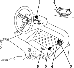
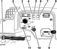
The ignition switch is used to start, stop, and preheat the engine. The ignition switch has 3 positions: OFF, ON/PREHEAT, and START. Rotate the key to the ON/PREHEAT position until the glow-plug-indicator light goes out (approximately 7 seconds); then rotate the key to the START position to engage the starter motor. Release the key when the engine starts (Figure 23).
To shut the engine off, rotate the key to the OFF position.
Note: Remove the key from the switch to prevent accidental starting.
Throttle
Move the throttle forward to increase the engine speed and rearward to decrease the engine speed (Figure 23).
Cutting-Unit-Drive Switch
The cutting-unit-drive switch has 2 positions: ENGAGE and DISENGAGE. The rocker switch operates a solenoid valve on the valve bank to drive the cutting units (Figure 23).
Hour Meter
The hour meter indicates the total hours of machine operation. The hour meter starts to function whenever the key switch is in the ON position (Figure 23).
Cutting-Unit-Shift Lever
To lower the cutting units to the ground, move the cutting-unit-shift lever forward. To raise the cutting units, pull the shift lever rearward to the RAISE position (Figure 23).
Note: The cutting units do not drop unless the engine is running.
For Models 30807, 30839, and 30849, move the lever to the right or left to move the cutting units in the same direction.
Note: Do this only when the cutting units are raised or if they are on the ground and the machine is moving.
Note: The lever does not need to be held in the forward position while you are lowering the cutting units.
Engine-Coolant-Temperature-Warning Light
The temperature-warning light glows if the engine coolant temperature is too high. If the traction unit is not stopped and the coolant temperature rises another 10°, the engine shuts off (Figure 23).
Oil-Pressure-Warning Light
The oil-pressure warning light glows if the engine oil pressure drops below a safe level (Figure 23).
Alternator Light
The alternator light should be off when the engine is running (Figure 23).
Note: If it is on, the charging system should be checked and repaired as necessary.
Glow-Plug-Indicator Light
The glow-plug-indicator light glows when the glow plugs are operating (Figure 23).
Parking Brake
Whenever the engine is shut off, engage the parking brake to prevent accidental movement of the machine. To engage the parking brake, pull up on the lever (Figure 23).
Note: The engine stops when you press the traction pedal with the parking brake engaged.
Lift-Lever Lock
Move the lift-lever lock rearward to prevent the cutting units from dropping (Figure 23).
Fuel Gauge
The fuel gauge registers the amount of fuel in the tank (Figure 24).
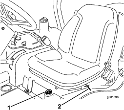
Seat-Adjustment Lever
Move the seat-adjustment lever on the side of the seat outward, slide the seat to the desired position, and release the lever to lock the seat into position (Figure 24).
Note: Specifications and design are subject to change without notice.
| Traction Unit | |
|---|---|
| Overall width: 68-inch width of cut | 182 cm (71.8 inches) |
| Overall width: 72-inch width of cut | 193 cm (75.8 inches) |
| Length | 295 cm (116 inches) |
| Height to top of the ROPS | 180 cm (70.8 inches) |
| Wheel base | 149 cm) (58.5 inches) |
| Track width | 145 cm (57 inches) |
| Ground clearance | 15.3 cm (6 inches) |
| Weight of cutting unitsModels 30807, 30839, and 30843 Model 30849 | 963 kg (2,124 lb)952 kg (2,099 lb) |
| Cutting Deck | |
| Length | 86.4 cm (34 inches) |
| Width | 86.4 cm (34 inches) |
| Height | 24.4 cm (9.6 inches) to carrier mount26.7 cm (10-1/2 inches) at 3/4-inch height of cut34.9 cm (13-3/4 inches) at 4-inch height of cut |
| Weight | 88 kg (195 lb) |
Attachments/Accessories
A selection of Toro approved attachments and accessories is available for use with the machine to enhance and expand its capabilities. Contact your Authorized Service Dealer or Distributor or go to www.Toro.com for a list of all approved attachments and accessories.
Operation
Note: Determine the left and right sides of the machine from the normal operating position.
Before Operation
Before Operation Safety
General Safety
-
Never allow children or untrained people to operate or service the machine. Local regulations may restrict the age of the operator. The owner is responsible for training all operators and mechanics.
-
Become familiar with the safe operation of the equipment, operator controls, and safety signs. Know how to stop the machine and engine quickly.
-
Check that all safety devices are attached and functioning properly. This includes, but is not limited to, operator-presence controls; safety switches and shields; the rollover protection system (ROPS); attachments; and brakes. Do not operate the machine unless all safety devices are in position and functioning as intended by the manufacturer.
-
Always inspect the machine to ensure that the blades, blade bolts, and cutting assembly are not worn or damaged. Replace worn or damaged blades and bolts in sets to preserve balance.
-
Inspect the area where you will use the machine and remove all objects that the machine could potentially throw.
-
Evaluate the terrain to determine the appropriate equipment and any attachments or accessories required to operate the machine properly and safely.
Fuel Safety
Danger
In certain conditions, fuel is extremely flammable and highly explosive. A fire or explosion from fuel can burn you and others and can damage property.
-
Fill the fuel tank outdoors, in an open area, when the engine is cold. Wipe up any fuel that spills.
-
Never fill the fuel tank inside an enclosed trailer.
-
Never smoke when handling fuel, and stay away from an open flame or where fuel fumes may be ignited by a spark.
-
Store fuel in an approved container and keep it out of the reach of children. Never buy more than a 180-day supply of fuel.
-
Do not operate the machine without the entire exhaust system in place and in proper working condition.
Warning
Fuel is harmful or fatal if swallowed. Long-term exposure to vapors can cause serious injury and illness.
-
Avoid prolonged breathing of vapors.
-
Keep your hands and face away from the nozzle and the fuel-tank opening.
-
Keep fuel away from your eyes and skin.
-
Use only an approved fuel container.
-
Never remove the fuel cap or add fuel to the fuel tank while the engine is running.
-
Never fill containers inside a vehicle or on a truck or trailer bed with a plastic liner. Always place containers on the ground and away from your vehicle before filling.
-
Remove the equipment from the truck or trailer and add fuel to it while it is on the ground. If this is not possible, then add fuel using a portable container rather than from a fuel-dispenser nozzle.
-
Keep the fuel-dispenser nozzle in contact with the rim of the fuel tank or container opening at all times until fueling is complete. Do not use a nozzle lock-open device.
-
If you spill fuel on your clothing, change your clothing immediately.
-
Fill the fuel tank until the fuel level is 25 mm (1 inch) below the bottom of the filler neck. Do not overfill the fuel tank. Replace the fuel-tank cap and tighten it securely.
Selecting a Blade
Using a Standard-Combination Sail Blade
This blade provides excellent lift and dispersion in almost any condition. If more or less lift and discharge velocity is required, consider a different blade.
Attributes: It has excellent lift and dispersion in most conditions.
Using an Angled-Sail Blade
The blade generally performs best in lower heights of cut—1.9 to 6.4 cm (3/4 to 2-1/2 inches).
Attributes:
-
The discharge remains more even at lower heights of cut.
-
The discharge has less tendency to throw left and thus leaves a cleaner look around bunkers and fairways.
-
There is a lower power requirement at lower heights of cut and in dense turf.
Using a High-Lift-Parallel Sail Blade
The blade generally performs better in the higher heights of cut—7 to 10 cm (2 to 4 inches).
Attributes:
-
There is more lift and a higher discharge velocity.
-
Sparse or limp turf is picked up significantly at higher heights of cut.
-
Wet or sticky clippings are discharged more efficiently, reducing congestion in the deck.
-
It requires more horsepower to run.
-
It tends to discharge further left and tends to windrow at lower heights of cut.
Warning
Using the high-lift blade with the mulching baffle may cause the blade could break, resulting in personal injury or death.
Do not use the high-lift blade with the mulching baffle.
Using an Atomic Blade
Attributes: This blade provides excellent leaf mulching.
Selecting Accessories
Optional-Equipment Configurations
| Angle-Sail Blade | High-Lift-Parallel Sail Blade(Do not use with the mulching baffle) | Mulching Baffle | Roller Scraper | |
| Grass cutting: 1.9 to 4.4 cm (0.75 to 1.75 inches) height of cut | Recommended in most applications | May work well in light or sparse turf | Has been shown to improve dispersion and after-cut performance on northern grasses that are cut at least 3 times per week and less than 1/3 of the grass blade is removed. Do not use with the high-lift-parallel sail blade | Can be used any time that rollers build up with grass or large, flat grass clumps of grass are seen; the scrapers may actually increase clumping in certain applications |
| Grass cutting: 5 to 6.4 cm (2 to 2.5 inches) height of cut | Recommended for thick or lush turf | Recommended for light or sparse turf | ||
| Grass cutting: 7 to 10 cm (2.75 to 4 inches) height of cut | May work well in lush turf | Recommended in most applications | ||
| Leaf mulching | Recommended for use with the mulching baffle | Not Allowed | Use with combination sail or angle-sail blade only | |
| Pros | Even discharge at a lower height of cut; cleaner look around bunkers and fairways; lower power requirements | More lift and higher discharge velocity; sparse or limp turf is picked up at a high height of cut; wet or sticky clippings are discharged efficiently | May improve dispersion and appearance in certain grass cutting applications; good for leaf mulching | Reduces roller buildup in certain applications |
| Cons | Does not lift the grass well in high height-of-cut applications; wet or sticky grass has a tendency to build up in the chamber, leading to poor quality of cut and higher power requirements | Requires more power to run in some applications; tends to windrow at a lower height of cut in lush grass; do not use with the mulching baffle | Grass will build up in the chamber if attempting to remove too much grass with baffle in place |
Checking the Engine-Oil Level
Before you start the engine and use the machine, check the oil level in the engine crankcase; refer to Checking the Engine-Oil Level.
Checking the Cooling System
Before you start the engine and use the machine, check the cooling system; refer to Checking the Cooling System.
Checking the Hydraulic System
Before you start the engine and use the machine, check the hydraulic system; refer to Checking the Hydraulic System.
Filling the Fuel Tank
Use only clean, fresh diesel fuel or biodiesel fuels with low (<500 ppm) or ultra low (<15 ppm) sulfur content. The minimum cetane rating should be 40. Purchase fuel in quantities that can be used within 180 days to ensure fuel freshness.
The fuel tank capacity is approximately 42 L (11 US gallons).
Use summer grade diesel fuel (No. 2-D) at temperatures above -7° C (20° F) and winter grade (No. 1-D or No. 1-D/2-D blend) below that temperature.
Using winter grade fuel at lower temperatures provides lower flash point and cold flow characteristics which will ease starting and reduce fuel filter plugging.
Using summer-grade fuel above -7° C (20° F) contributes toward longer fuel pump life and increased power compared to winter-grade fuel.
Biodiesel Ready
This machine can also use a biodiesel blended fuel of up to B20 (20% biodiesel, 80% petrodiesel). The petrodiesel portion should be low or ultra low sulfur. Observe the following precautions:
-
The biodiesel portion of the fuel must meet specification ASTM D6751 or EN14214.
-
The blended fuel composition should meet ASTM D975 or EN590.
-
Biodiesel blends may damage painted surfaces.
-
Use B5 (biodiesel content of 5%) or lesser blends in cold weather
-
Monitor seals, hoses, gaskets in contact with fuel as they may degrade over time.
-
Fuel filter plugging may occur for a time after converting to biodiesel blends.
-
Contact your distributor for more information about biodiesel fuel.
-
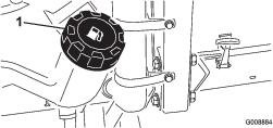
Clean the area around the fuel-tank cap (Figure 25).
-
Remove the fuel-tank cap.
-
Fill the tank to the bottom of the filler neck. Do not overfill. Install the cap.
-
To prevent a fire hazard, wipe up any fuel that may have spilled.
Checking the Tire Pressure
Danger
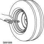
Low tire pressure decreases machine side-hill stability. This could cause a rollover, which may result in personal injury or death.
Do not underinflate the tires.
The correct air pressure in the tires is 97 to 124 kPa (14 to 18 psi) as shown in Figure 26.
Important: Maintain pressure in all tires to ensure a good quality of cut and proper machine performance.Check the air pressure in all the tires before operating the machine.
Checking the Torque of the Wheel-Lug Nuts
| Maintenance Service Interval | Maintenance Procedure |
|---|---|
| After the first hour |
|
| After the first 10 hours |
|
| Every 200 hours |
|
Torque the wheel-lug nuts to 61 to 88 N∙m (45 to 65 ft-lb).
Warning
Failing to maintain proper torque of the wheel-lug nuts could result in personal injury.
Torque the wheel-lug nuts to the proper torque value.
Checking the Safety-Interlock System
| Maintenance Service Interval | Maintenance Procedure |
|---|---|
| Before each use or daily |
|
Caution
If the safety-interlock switches are disconnected or damaged, the machine could operate unexpectedly and cause personal injury.
-
Do not tamper with the safety systems.
-
Check the operation of the switches daily and replace any damaged switches before operating the machine.
-
Drive the machine slowly to a large, open area..
-
Lower the cutting unit(s), shut off the engine, and engage the parking brake.
-
While sitting on the seat, the engine must not start with either the cutting-unit switch engaged or the traction pedal engaged.
Note: Correct the problem if it is not operating properly.
-
While sitting on the seat, put the traction pedal in NEUTRAL, the parking brake OFF, and the cutting unit switch in the OFF position.
Note: The engine should start. Rise from the seat and slowly press the traction pedal, and the engine should shut off in 1 to 3 seconds. If it does not shut off, there is a malfunction in the interlock system that you should correct before resuming operation.
Note: The machine is equipped with an interlock switch on the parking brake. The engine shuts off when you press the traction pedal with the parking brake engaged.
During Operation
During Operation Safety
General Safety
-
The owner/user can prevent and is responsible for accidents that may cause injuries to himself/herself and others and for damage to property.
-
Wear appropriate clothing, including eye protection; slip-resistant, substantial footwear; and hearing protection. Wearing safety shoes and long pants is advisable and required by some local ordinances and insurance regulations. Tie back long hair, secure loose clothing, and do not wear jewelry.
-
Ensure that all drives are in the NEUTRAL position, the parking brake is engaged, and you are in the operating position before you start the engine.
-
Keep all body parts, including hands and feet, away from all moving parts.
-
Do not operate the machine while ill, tired, or under the influence of alcohol or drugs.
-
Keep the direction of the mower discharge away from people and pets.
-
Do not mow in reverse unless it is absolutely necessary. If you must mow in reverse, look behind and down for small children before and while moving the machine in reverse. Stay alert and stop the machine if a child enters the area.
-
Use extreme care when approaching blind corners, shrubs, trees, or other objects that may block your view.
-
Do not mow near drop-offs, ditches, or embankments. The machine could suddenly roll over if a wheel goes over the edge or if the edge caves in.
-
Never carry passengers on the machine.
-
Operate the machine only in good visibility and appropriate weather conditions. Do not operate the machine when there is the risk of lighting.
-
Do not mow on wet grass. Reduced traction could cause the machine to slide.
-
Never raise the mower deck with the blades running.
-
Stop the machine and inspect the blades after striking an object or if there is an abnormal vibration in the machine. Make all necessary repairs before resuming operation.
-
Stop the blades whenever you are not mowing, especially while crossing loose terrain such as gravel.
-
Slow down and use caution when making turns and crossing roads and sidewalks with the machine. Always yield the right-of-way.
-
Turn on the flashing warning lights on the machine whenever you travel on a public road, except where such use is prohibited by law.
-
Disengage the drive to the attachment and shut off the engine before adding fuel and adjusting the height of cut.
-
Reduce the throttle setting before stopping the engine and, if the engine has a fuel-shutoff valve, shut off the fuel when you have finished operating the machine.
-
Never run an engine in an area where exhaust gases are enclosed.
-
Never leave a running engine unattended.
-
Before leaving the operating position, do the following:
-
Stop the machine on level ground.
-
Disengage the power take-off and lower the attachments.
-
Set the parking brake.
-
Shut off the engine and remove the key.
-
Wait for all moving parts to stop.
-
-
Do not change the governor settings on or overspeed the engine. Operating the engine at excessive speed may increase the potential for personal injury.
-
Do not use the machine as a towing vehicle.
-
Use accessories and attachments approved by The Toro® Company only.
Rollover Protection System (ROPS) Safety
-
Do not remove the ROPS from the machine.
-
Ensure that the seat belt is attached and that you can release it quickly in the event of an emergency.
-
Always wear your seat belt when the ROPS is up.
-
Check carefully for overhead clearances, such as branches, doorways, and electrical wires, before driving the machine under them. Do not contact them.
-
Keep the ROPS in safe operating condition by thoroughly inspecting it periodically for damage and keeping all the mounting fasteners tight.
-
Replace a damaged ROPS. Do not repair or revise it.
-
Any alterations to a ROPS must be approved by The Toro® Company.
Slope Safety
-
Slow down the machine and use extra care on hillsides. Travel in the recommended direction on hillsides. Turf conditions can affect the stability of the machine.
-
Avoid starting, stopping, or turning the machine on a slope. If the tires lose traction, disengage the blade(s) and proceed slowly straight down the slope.
-
Do not turn the machine sharply. Use care when reversing the machine.
-
When operating the machine on a slope, always keep all cutting units lowered.
-
Avoid turning the machine on slopes. If you must turn, turn slowly and gradually downhill, if possible.
-
Use extra care while operating the machine with attachments; they can affect the stability of the machine.
Starting and Stopping the Engine
Starting the Engine
-
Ensure that the parking brake is set and the cutting-unit-drive switch is in the DISENGAGE position.
-
Remove your foot from the traction pedal and ensure that the pedal is in the NEUTRAL position.
-
Move the throttle lever to the 1/2-throttle position.
-
Insert the key into the switch and rotate it to the ON/PREHEAT position until the glow-plug indicator light goes out (approximately 7 seconds); then rotate the key to the START position to engage the starter motor.
Important: To prevent overheating of the starter motor, do not engage the starter for longer than 15 seconds. After 10 seconds of continuous cranking, wait 60 seconds before engaging the starter motor again.
-
Release the key when the engine starts.
Note: The key automatically moves to the ON/RUN position.
-
When you start the engine for the first time or after overhauling the engine, operate the machine in forward and reverse for 1 to 2 minutes.
Note: Also, operate the lift lever and cutting-unit-drive switch to ensure that all parts operate properly.
-
Turn the steering wheel to the left and to the right to check the steering response, then shut off the engine check for oil leaks, loose parts, and any other malfunctions.
Stopping the Engine
Move the throttle control to the IDLE position, move the cutting-unit-drive switch to the DISENGAGE position, and rotate the starter key to the OFF position. Remove the key to prevent accidental starting.
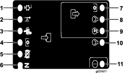
Standard-Control Module (SCM)
The Standard-Control Module (SCM) is a potted electronic device produced in a 1-size-fits-all configuration. The module uses solid state and mechanical components to monitor and control standard, electrical features required for safe product operation.
The module-monitor input includes neutral, parking brake, PTO, start, backlap, and high temperature. The module energizes outputs including PTO, Starter, and ETR (energize to run) solenoid.
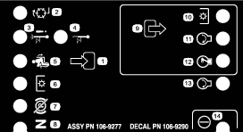
The module is divided into inputs and outputs. Inputs and outputs are identified by green LED indicators mounted on the printed circuit board.
The start-circuit input is energized by 12 VDC. All other inputs are energized when the circuit is closed to ground. Each input has an LED that illuminates when the specific circuit is energized. Use the input LEDs for switch and input-circuit troubleshooting.
Output circuits are energized by an appropriate set of input conditions. The 3 outputs include PTO, ETR, and START. Output LEDs monitor the relay condition, indicating the presence of voltage at 1 of 3 specific output terminals.
Output circuits do not determine output-device integrity, so electrical troubleshooting includes output-LED inspection, conventional device, and wire-harness-integrity testing. Measure the disconnected-component impedance, impedance through the wire harness (disconnect at SCM), or by temporarily ”test energizing” the specific component.
The SCM does not connect to an external computer or handheld device, cannot be programmed again, and does not record intermittent fault troubleshooting data.
The decal on the SCM includes only symbols. The 3 LED output symbols are shown in the output box, while all other LEDs are inputs as shown in Figure 27.
Here are the logical troubleshooting steps for the SCM device.
-
Determine the output fault that you are trying to resolve (PTO, START, or ETR).
-
Move key switch to the ON position and ensure that the red, power LED illuminates.
-
Move all of the input switches to ensure that all LEDs change state.
-
Position the input devices at the appropriate position to achieve the appropriate output.
Note: Use the following logic chart to determine the appropriate input condition.
-
Review the following repair options if a specific output LED illuminates.
-
If a specific output LED illuminates without the appropriate output function, check the output harness, connections, and component.
Note: Repair as required.
-
If a specific output LED does not illuminate, check both fuses.
-
If a specific output LED does not illuminate and the inputs are in the appropriate condition, install a new SCM and determine if the fault disappears.
-
Each row (across) in the logic chart below identifies input and output requirements for each specific product function. Product functions are listed in the left column. Symbols identify specific circuit condition, including energized to voltage, closed to ground, and open to ground.
| Inputs | Outputs | ||||||||||
|---|---|---|---|---|---|---|---|---|---|---|---|
| Function | Power ON | In NEUTRAL | Start ON | Brake ON | PTO ON | In Seat | Hi Temp | Backlap | Start | ETR | PTO |
| Start | — | — | + | O | O | — | O | O | + | + | O |
| Run (Off Unit) | — | — | O | O | O | O | O | O | O | + | O |
| Run (On Unit) | — | O | O | — | O | — | O | O | O | + | O |
| Mow | — | O | O | — | — | — | O | O | O | + | + |
| Backlap | — | — | O | O | — | O | O | — | O | + | + |
| Hi Temp | — | O | — | O | O | O | |||||
-
(–) Indicates a circuit closed to ground—LED On
-
(O) Indicates a circuit open to ground or de-energized—LED Off
-
(+) Indicates an energized circuit (clutch coil, solenoid, or start input)—LED On
-
A blank indicates a circuit that is not involved with the logic chart.
To troubleshoot, turn on the key without starting the engine. Identify the specific function that does not work and work across the logic chart. Inspect the condition of each input LED to ensure that it matches the logic chart.
If the input LEDs are correct, check the output LED. If the output LED illuminates but the device is not energized, measure the available voltage at the output device, the continuity of the disconnected device, and the potential voltage on the ground circuit (floating ground).
Operating Tips
Operating the Machine
-
Start the engine and run it at HALF IDLE until it warms up. Push the throttle lever all the way forward, lift the cutting units, disengage the parking brake, press the forward traction pedal, and carefully drive to an open area.
-
Practice moving forward and reverse, and starting and stopping the machine. To stop the machine, remove your foot from the traction pedal and let it return to NEUTRAL or press down on the reverse pedal.
Note: When going downhill in the machine, you may need to use the reverse pedal to stop.
-
When possible, mow up and down hills rather than across them. Have the cutting units lowered when going down a hill to maintain steering control. Do not attempt to turn the machine on a hill.
-
Practice driving around obstacles with the cutting units up and down. Be careful when driving between narrow objects so that you do not damage the machine or cutting units.
-
On the Sidewinder unit, get accustomed to the reach of the cutting units so that you do not hang them up or damage them.
-
Do not shift the cutting units from side to side unless they are down and the machine is moving, or the cutting units are in the transport position. Shifting the cutting units when they are down and the machine is not moving may damage the turf.
-
Always drive slowly in rough areas.
-
The Sidewinder unit offers up to a maximum of 33 cm (13 inches) of overhang, allowing you to trim closer to the edge of sand traps and other obstacles, while, at the same time, keeping the tractor tires as far away from the edge of traps or water hazards as possible.
-
If an obstacle is in the way, shift the cutting units to mow around it.
-
When transporting the machine from 1 work area to another, raise the cutting units to the fully upward position, move the mow/transport slide to the left to transport, and place the throttle in the FAST position.
Changing Mowing Patterns
Change mowing patterns often to minimize a poor after-cut appearance from repeatedly mowing in the same direction.
Understanding Counterbalance
The counterbalance system maintains hydraulic back pressure on the deck-lift cylinders. This counterbalance pressure transfers mower deck weight to the mower drive wheels to improve traction. The counterbalance pressure has been set at the factory to an optimal balance of after-cut appearance and traction capability in most turf conditions. Decreasing the counterbalance setting can produce a more stable mower deck, but can decrease the traction capability. Increasing the counterbalance setting can increase the traction capability, but may result in a poor after-cut appearance. Refer to the Service Manual for your traction unit for instructions to adjust the counterbalance pressure.
Resolving After-Cut Appearance
Reference the After-cut Appearance Troubleshooting Guide available at www.Toro.com.
Using Proper Mowing Techniques
-
To begin cutting, engage the cutting units, then approach the mowing area slowly. Once the front cutting units are over the mowing area, lower the cutting units.
-
To achieve the professional straight-line cut and striping that is desirable for some applications, find a tree or other object in the distance and drive straight toward it.
-
As soon as the front cutting units reach the edge of the mowing area, lift the cutting units, and perform a tear-drop-shaped turn to quickly line up for your next pass.
-
To mow around bunkers, ponds, or other contours easily, use the Sidewinder unit and move the control lever to the left or right, depending on your mowing application. You can also shift the cutting units to vary the tire tracking.
-
The cutting units tend to throw grass to the left side of the machine. If you are trimming around bunkers, it is best to mow in a clockwise direction to prevent throwing clippings into the bunker.
-
Bolt-in mulching baffles are available for the cutting units. The mulching baffles perform well when you maintain turf on a regular schedule to avoid removing more than 25 mm (1 inch) of growth per cutting. When you cut too much growth with the mulching baffles installed, the after-cut appearance may deteriorate and the observed power to cut the turf increases. The mulching baffles also perform well for shredding leaves in the fall.
Mowing When the Grass Is Dry
Mow either in the late morning to avoid the dew, which causes grass clumping, or late afternoon to avoid the damage that direct sunlight can cause on the sensitive, freshly mowed grass.
Selecting the Proper Height-of-Cut Setting to Suit Conditions
Remove approximately 25 mm (1 inch), or no more than 1/3 of the grass blade when cutting. In exceptionally lush and dense grass, you may need to raise your height-of-cut setting.
Mowing with Sharp Blades
A sharp blade cuts cleanly and without tearing or shredding the grass blades like a dull blade. Tearing and shredding causes the grass to turn brown at the edges, which impairs growth and increases susceptibility to diseases. Ensure that the blade is in good condition and that there is a full sail.
Checking the Condition of the Mower Deck
Ensure that the cutting chambers are in good condition. Straighten any bends in the chamber components to ensure correct blade tip/chamber clearance.
Maintaining the Machine After Mowing
After mowing, thoroughly wash the machine with a garden hose with no nozzle to avoid contamination and damage to the seals and bearings caused by excessive water pressure. Ensure that the radiator and oil cooler are kept free of dirt or grass clippings. After cleaning, inspect the machine for possible hydraulic-fluid leaks, damage, or wear to the hydraulic and mechanical components, and check the cutting-unit blades for sharpness.
Important: After washing the machine, move the Sidewinder mechanism from left to right several times to remove the water between the bearing blocks and cross tube.
After Operation
After Operation Safety
General Safety
-
Clean grass and debris from the cutting units, drives, mufflers, and engine to help prevent fires. Clean up oil or fuel spills.
-
Shut off the fuel while storing or transporting the machine.
-
Disengage the drive to the attachment whenever you are transporting or not using the machine.
-
Use full-width ramps for loading the machine into a trailer or truck. Do not exceed a 15° angle between the ramp and the trailer or truck.
-
Tie the machine down securely using straps, chains, cable, or ropes. Both front and rear straps should be directed down and outward from the machine.
-
Allow the engine to cool before storing the machine in any enclosure.
-
Never store the machine or fuel container where there is an open flame, spark, or pilot light, such as on a water heater or on other appliances.
Towing Safety
-
Tow only with a machine that has a hitch designed for towing. Do not attach towed equipment except at the hitch point.
-
Follow the manufacturer’s recommendation for weight limits for towed equipment and towing on slopes. On slopes, the weight of the towed equipment may cause loss of traction and loss of control.
-
Never allow children or others in or on towed equipment.
-
Travel slowly and allow extra distance to stop when towing.
Towing the Traction Unit
Important: In an emergency, you can tow the machine for a short distance. Do not tow the machine at faster than 3 to 4 km/h (2 to 3 mph); otherwise, you may damage the drive system. If you must move the machine a considerable distance, transport it on a truck or trailer.
-
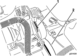
Locate the bypass valve on the pump and rotate it 90° (Figure 28).
-
Before starting the engine, close the bypass valve by rotating it 90° (1/4 turn).
Important: Do not start the engine when the valve is open, as this may cause damage.
Maintenance
Note: Determine the left and right sides of the machine from the normal operating position.
Recommended Maintenance Schedule(s)
| Maintenance Service Interval | Maintenance Procedure |
|---|---|
| After the first hour |
|
| After the first 10 hours |
|
| After the first 50 hours |
|
| Before each use or daily |
|
| Every 25 hours |
|
| Every 50 hours |
|
| Every 100 hours |
|
| Every 150 hours |
|
| Every 200 hours |
|
| Every 400 hours |
|
| Every 500 hours |
|
| Every 1,000 hours |
|
| Every 2 years |
|
Caution
If you leave the key in the ignition switch, someone could accidently start the engine and seriously injure you or other bystanders.
Remove the key from the ignition before you do any maintenance.
Service-Interval Chart
Pre-Maintenance Procedures
Pre-Maintenance Safety
-
Keep all parts of the machine in good working condition and all hardware tightened, especially blade-attachment hardware. Replace all worn or damaged decals.
-
Never allow untrained personnel to service the machine.
-
Before adjusting, cleaning, or repairing the machine, do the following:
-
Move the machine to level ground.
-
Disengage the drives.
-
Lower the cutting units.
-
Move the traction pedal to the NEUTRAL position.
-
Engage the parking brake.
-
Move the throttle switch to the LOW-IDLE position.
-
Shut off the engine and remove the key.
-
Wait for all moving parts to stop.
-
-
Whenever you park or store the machine, or leave it unattended, lower the cutting units unless you use a positive mechanical lock.
-
If possible, do not perform maintenance on the machine while the engine is running. If you must run the engine to perform maintenance on the machine, keep your hands, feet, other body parts, and clothing away from all moving parts, the mower-discharge area, and the underside of the mowers.
-
Do not touch parts of the machine or an attachment that may be hot from operation. Allow the parts to cool before attempting to maintain, adjust, or service them.
-
Use jack stands to support the machine and/or its components when required.
-
Carefully release pressure from components with stored energy.
-
If your machine requires major repairs or if you desire assistance, contact an Authorized Toro Distributor.
-
Use only genuine Toro replacement parts and accessories. Replacement parts and accessories made by other manufacturers could be dangerous, and such use could void the product warranty.
Preparing the Machine for Maintenance
-
Ensure that the PTO is disengaged.
-
Park the machine on a level surface.
-
Set the parking brake.
-
Lower the cutting unit(s) if necessary.
-
Shut off the engine and wait for all moving parts to stop.
-
Turn the ignition key to the STOP position and remove it.
-
Allow machine components to cool before performing maintenance.
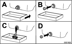
Removing the Hood
-
Unlatch and raise the hood.
-
Remove the hairpin cotter securing the hood pivot to the mounting brackets (Figure 30).
-
Slide the hood to the right side, lift the other side, and pull it out of the brackets.
Note: Reverse this procedure to install the hood.
Using the Cutting Deck Service Latch
When servicing the cutting decks, use the service latch to prevent injury.
-
Center the cutting deck sidewinder with the traction unit.
-
Raise the cutting decks to the transport position.
-
Set the parking brake and turn off the machine.
-
Release the latch rod from the front carrier-frame retainer (Figure 31).
-
Lift the outside of the front cutting decks and place the latch over the frame pin mounted on the front of the operator's platform (Figure 31).
-
Sit on the operator’s seat and start the machine.
-
Lower the cutting decks to the mow position.
-
Turn off the machine and remove the key.
-
Reverse this procedure to unlatch the cutting decks.
Lubrication
Greasing the Bearings and Bushings
| Maintenance Service Interval | Maintenance Procedure |
|---|---|
| Every 50 hours |
|
| Every 500 hours |
|
The machine has grease fittings that you must lubricate regularly with No. 2 lithium grease. Also, lubricate the machine immediately after every washing.
The grease fitting locations and quantities are as follows:
-
Rear cutting-unit pivot (Figure 32)
-
Front cutting-unit pivot (Figure 33)
-
2 sidewinder-cylinder ends (Figure 34)
-
Steering pivot (Figure 35)
-
2 rear lift-arm pivots and lift cylinder (Figure 36)
-
2 left, front lift-arm pivots and lift cylinder (Figure 37)
-
2 right, front lift-arm pivots and lift cylinder (Figure 38)
-
Neutral-adjustment mechanism (Figure 39)
-
Mow/transport slide (Figure 40)
-
Belt-tension pivot (Figure 41)
-
Steering cylinder (Figure 42).
Note: If desired, an additional grease fitting may be installed at the other end of the steering cylinder. Remove the tire, install the fitting, grease the fitting, remove the fitting, and install the plug (Figure 43).
-
2 (per cutting unit) cutting unit spindle-shaft bearings (Figure 44)
Note: You can use either fitting, whichever is more accessible. Pump grease into the fitting until a small amount appears at the bottom of the spindle housing (under the deck).
-
2 (per cutting unit) rear roller bearings (Figure 45)

Note: Ensure that the grease groove in each roller mount aligns with the grease hole in each end of the roller shaft. To help align the groove and hole, there is also an alignment mark on an end of the roller shaft.
Important: Do not lubricate the Sidewinder cross tube. The bearing blocks are self-lubricated.
Engine Maintenance
Engine Safety
Shut off the engine before checking the oil or adding oil to the crankcase.
Servicing the Engine Oil
Checking the Engine-Oil Level
| Maintenance Service Interval | Maintenance Procedure |
|---|---|
| Before each use or daily |
|
The engine is shipped with oil in the crankcase; however, check the oil level before and after you start the engine for the first time.
The crankcase capacity is approximately 2.8 L (4 US qt) with the filter.
Use high-quality engine oil that meets the following specifications:
-
API Classification Level Required: CH-4, CI-4, or higher.
-
Preferred oil: SAE 15W-40 above -17º C (0º F)
-
Alternate oil: SAE 10W-30 or 5W-30 (all temperatures)
Note: Toro Premium Engine Oil is available from your distributor in either 15W-40 or 10W-30 viscosity. See the parts catalog for part numbers. Also, refer to the engine owner's manual (included with the machine) for further recommendations.
Note: The best time to check the engine oil is when the engine is cool before it has been started for the day. If you have already run the engine, allow the oil to drain back down to the sump for at least 10 minutes before checking. If the oil level is at or below the ADD mark on the dipstick, add oil to bring the oil level to the FULL mark. Do not overfill. If the oil level is between the FULL and ADD marks, you do not need to add oil.
Check the engine-oil level as shown in Figure 46.
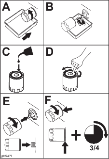
Changing the Engine Oil and Filter
| Maintenance Service Interval | Maintenance Procedure |
|---|---|
| After the first 50 hours |
|
| Every 150 hours |
|
-
Start the engine and let it run 5 minutes to allow the oil to warm up.
-
With the machine parked on a level surface, stop the engine, remove the key, and wait for all moving parts to stop before leaving the operating position.
-
Change the engine oil as shown in Figure 47.
-
Change the engine-oil filter as shown in Figure 48.
Servicing the Air Cleaner
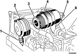
Check the air-cleaner body for damage that could cause an air leak and replace it if it is damaged. Check the entire intake system for leaks, damage, or loose hose clamps. Also, inspect the rubber intake-hose connections at the air cleaner and turbocharger to ensure that the connections are complete.
Ensure that the cover is seated correctly and seals with the air-cleaner body.
Servicing the Air-Cleaner Cover
| Maintenance Service Interval | Maintenance Procedure |
|---|---|
| Every 50 hours |
|
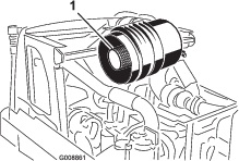
Check the air-cleaner body for damage which could cause an air leak. Replace a damaged air cleaner body.
Clean the air-cleaner cover (Figure 49).
Servicing the Air-Cleaner Filter
| Maintenance Service Interval | Maintenance Procedure |
|---|---|
| Every 200 hours |
|
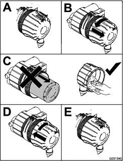
-
Before removing the filter, use clean and dry, low-pressure air (275 kPa or 40 psi) to help remove large accumulations of debris packed between the outside of the primary filter and the canister.
Important: Avoid using high-pressure air that could force dirt through the filter and into the intake tract, causing damage. This cleaning process prevents debris from migrating into the intake when you remove the primary filter.
-
Remove the primary filter (Figure 50).
Important: Do not clean the used element to prevent the possibility of damaging the filter media. Inspect the new filter for shipping damage, checking the sealing end of the filter and the body. Do not use a damaged element.
Important: Do not attempt to clean the safety filter. Replace the safety filter after every 3 primary-filter services (Figure 51).
-
Replace the primary filter (Figure 50).
-
Insert the new filter by applying pressure to the outer rim of the element to seat it in the canister.
Note: Do not apply pressure to the flexible center of the filter.
-
Clean the dirt-ejection port located in the removable cover.
-
Remove the rubber outlet valve from the cover, clean the cavity, and replace the outlet valve.
-
Install the cover, orienting the rubber outlet valve in a downward position between the 5 o’clock to 7 o’clock positions when viewed from the end, and secure the latch (Figure 50).
Fuel System Maintenance
Draining the Fuel Tank
| Maintenance Service Interval | Maintenance Procedure |
|---|---|
| Every 1,000 hours |
|
| Every 2 years |
|
Drain and clean the tank also if the fuel system becomes contaminated or if you are storing the machine for an extended period of time. Use clean fuel to flush out the tank.
Servicing the Water Separator
| Maintenance Service Interval | Maintenance Procedure |
|---|---|
| Before each use or daily |
|
| Every 400 hours |
|
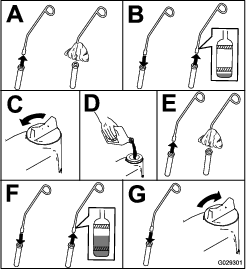
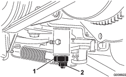
Draining the Water Separator
-
Place a drain pan under the fuel filter.
-
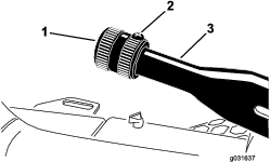
Loosen the drain valve on the bottom of the filter (Figure 52).
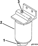
-
Tighten the valve after draining.
Replacing the Fuel Filter
-
Clean the area where the filter mounts (Figure 52).
-
Remove the filter and clean the mounting surface.
-
Lubricate the gasket on the filter with clean oil.
-
Install the filter by hand until the gasket contacts the mounting surface; then rotate an additional 1/2 turn.
Bleeding the Fuel System
-
Perform the pre-maintenance procedure; refer to Preparing the Machine for Maintenance
-
Ensure that the fuel tank is at least half full.
-
Unlatch and raise the hood.
Danger
Under certain conditions, diesel fuel and fuel vapors are highly flammable and explosive. A fire or explosion from fuel can burn you and others and can cause property damage.
Never smoke when handling fuel, and stay away from an open flame or where fuel fumes may be ignited by a spark.
-
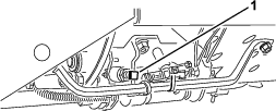
Open the air-bleed screw on the fuel-injection pump (Figure 53).
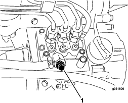
-
Turn the key in the ignition switch to the ON position.
Note: The electric fuel pump will operate, forcing air out around the air-bleed screw. Leave the key in the ON position until a solid stream of fuel flows out around the screw.
-
Tighten the screw and turn the key to the OFF position.
Note: Normally, the engine should start after performing this procedure. However, if the engine does not start, there may be air trapped between the injection pump and injectors; refer to Bleeding Air from the Injectors.
Bleeding Air from the Injectors
Note: Use this procedure only if the fuel system has been purged of air through normal priming procedures and the engine does not start; refer to Bleeding the Fuel System.
-
Loosen the pipe connection to the No. 1 nozzle and holder assembly (Figure 54).
-
Move the throttle to the FAST position.
-
Turn the key in the key switch to the START position and watch the fuel flow around the connector.
Note: Turn the key to the OFF position when solid flow is observed.
-
Tighten the pipe connector securely.
-
Repeat this procedure on the remaining nozzles.
Electrical System Maintenance
Electrical System Safety
-
Disconnect the battery before repairing the machine. Disconnect the negative terminal first and the positive last. Connect the positive terminal first and the negative last.
-
Battery acid is poisonous and can cause burns. Avoid contact with your skin, eyes, and clothing. Protect your face, eyes, and clothing when working with a battery.
-
Battery gases can explode. Keep cigarettes, sparks, and flames away from the battery.
-
Charge the batteries in an open, well-ventilated area, away from sparks and flames. Unplug the charger before connecting or disconnecting the battery. Wear protective clothing and use insulated tools.
-
Do not use a pressure washer near any electronic components.
Warning
Battery posts, terminals, and related accessories contain lead and lead compounds, chemicals known to the State of California to cause cancer and reproductive harm. Wash hands after handling.
Servicing the Battery
| Maintenance Service Interval | Maintenance Procedure |
|---|---|
| Every 25 hours |
|
Warning
Battery posts, terminals, and related accessories contain lead and lead compounds, chemicals known to the State of California to cause cancer and reproductive harm. Wash hands after handling.
Maintain the battery-electrolyte level properly and keep the top of the battery. If you store the machine in a hot location, the battery will discharge more rapidly than if you store the machine in a cool location.
Maintain the cell level with distilled or demineralized water. Do not fill the cells above the bottom of the split ring inside each cell. Install the filler caps with the vents pointing to the rear (toward the fuel tank).
Danger
Battery electrolyte contains sulfuric acid, a deadly poison that causes severe burns.
-
Do not drink electrolyte and avoid contact with skin, eyes, or clothing. Wear safety glasses to shield your eyes and rubber gloves to protect your hands.
-
Fill the battery where clean water is always available for flushing the skin.
Keep the top of the battery clean by washing it periodically with a brush dipped in ammonia or a solution of bicarbonate of soda. Flush the top surface with water after cleaning. Do not remove the filler caps while cleaning the battery.
The battery cables must be tight on the terminals to provide good electrical contact.
Warning
Incorrectly routing the battery cable could damage the tractor and cables, causing sparks. Sparks can cause the battery gases to explode, resulting in personal injury.
-
Always disconnect the negative (black) battery cable before disconnecting the positive (red) cable.
-
Always connect the positive (red) battery cable before connecting the negative (black) cable.
If the terminals have corrosion, disconnect the cables (the negative (–) cable first) and scrape the clamps and terminals separately. Connect the cables (positive (+) cable first) and coat the terminals with petroleum jelly.
Servicing the Fuses
The fuses in machines electrical system are located under console cover.
Drive System Maintenance
Adjusting the Traction Drive for Neutral
If the machine moves when the traction pedal is in the NEUTRAL position, adjust the traction cam.
-
Park the machine on a level surface, lower the cutting units, engage the parking brake, shut off the engine, and remove the key from the ignition switch.
-
Chock or block the front and rear wheels on one side.
-
Raise the opposite front and rear wheel off the floor and place support blocks under the frame.
Warning
If the machine is not supported adequately, it may accidentally fall, injuring anyone under the machine.
A front wheel and a rear wheel must be raised off the ground; otherwise, the machine will move during adjustment.
-
Loosen the locknut on the traction adjustment cam (Figure 55).
Warning
The engine must be running so that you can make a final adjustment of the traction adjustment cam. Contact with hot or moving parts can result in personal injury.
Keep your hands, feet, face, and other body parts away from the muffler, other hot parts of the engine, and rotating parts.
-
Start the engine and rotate the cam hex in both directions to determine the mid position of the neutral span.
-
Tighten the locknut securing the adjustment.
-
Shut off the engine.
-
Remove the support blocks and lower the machine to the shop floor. Test drive the machine to ensure that it does not move when the traction pedal is in neutral.
Cooling System Maintenance
Cooling System Safety
Caution
Discharge of hot, pressurized coolant or touching a hot radiator and surrounding parts can cause severe burns.
-
Do not remove the radiator cap when the engine is hot. Always allow the engine to cool at least 15 minutes or until the radiator cap is cool enough to touch without burning your hand before removing the radiator cap.
-
Do not touch the radiator and surrounding parts that are hot.
Danger
Swallowing engine coolant can cause poisoning.
-
Do not swallow engine coolant.
-
Keep out of reach from children and pets.
Checking the Cooling System
| Maintenance Service Interval | Maintenance Procedure |
|---|---|
| Before each use or daily |
|
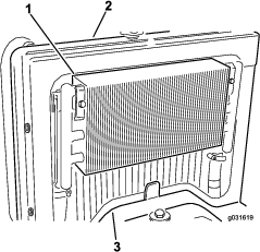
Clean debris off the radiator and oil cooler daily (Figure 56).
Clean the radiator hourly if conditions are extremely dusty and dirty; refer to Cleaning the Cooling System.
The cooling system is filled with a 50/50 solution of water and permanent ethylene glycol anti-freeze. Check the coolant level at the beginning of each day before starting the engine.
The capacity of the cooling system is approximately 5.7 L (6 US qt).
Caution
If the engine has been running, the pressurized, hot coolant can escape and cause burns.
-
Do not open the radiator cap when the engine is running.
-
Use a rag when opening the radiator cap, and open the cap slowly to allow steam to escape.
-
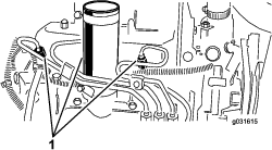
Check the coolant level in the expansion tank (Figure 57).
Note: With a cold engine, the coolant level should be approximately midway between the marks on the side of the tank.
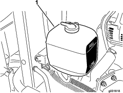
-
If the coolant level is low, remove the expansion-tank cap and replenish the system.
Note: Do not overfill.
-
Install the expansion-tank cap.
Cleaning the Cooling System
| Maintenance Service Interval | Maintenance Procedure |
|---|---|
| Before each use or daily |
|
-
Turn the engine off and raise the hood.
-
Clean the engine area thoroughly of all debris.
-
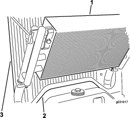
Remove the access panel (Figure 58).
-
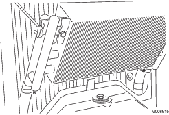
Unlatch the oil cooler and pivot it rearward (Figure 59).
-
Clean both sides of the oil cooler and radiator area thoroughly with water or compressed air.
-
Pivot the oil cooler back into position.
-
Install the access panel and close the hood.
Brake Maintenance
Adjusting the Parking Brake
| Maintenance Service Interval | Maintenance Procedure |
|---|---|
| Every 200 hours |
|
-
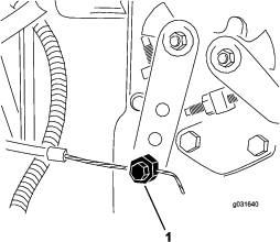
Loosen the set screw securing the knob to the parking-brake lever (Figure 60).
-
Torque the knob to 41 to 68 N∙m (30 to 40 in-lb) to actuate the lever.
-
Tighten the set screw.
Belt Maintenance
Servicing the Engine Belts
| Maintenance Service Interval | Maintenance Procedure |
|---|---|
| After the first 10 hours |
|
| Every 100 hours |
|
Tensioning the Alternator Belt
-
Open the hood.
-
Check the tension by pressing the belt midway between the alternator and crankshaft pulleys with 30 N∙m (22 in-lb) of force (Figure 61).
Note: The belt should deflect 11 mm (7/16 inch).
-
If the belt does not deflect 11 mm (7/16 inch), complete the following procedure to tension the belt:
-
Loosen the bolt securing the brace to the engine and the bolt securing the alternator to the brace.
-
Insert a pry bar between the alternator and engine, and pry out at the alternator.
-
When you obtain the proper tension, tighten the alternator and brace bolts to secure the adjustment.
-
Replacing the Hydrostat-Drive Belt
-
Insert a nut driver or small piece of tubing onto the end of the belt-tensioning spring.
Caution
The spring that tensions the belt is under a heavy load, and releasing the tension of the spring improperly may cause injury.
Use care when de-tensioning the spring and replacing the belt.
-
Push down and forward on the spring end to unhook it from the bracket and release tension on the spring (Figure 62).
-
Replace the belt.
-
Reverse this procedure to tension the spring.
Controls System Maintenance
Adjusting the Throttle
-
Position the throttle lever rearward so that it stops against the control-panel slot.
-
Loosen the throttle-cable connector on the injection-pump-lever arm (Figure 63).
-
Hold the injection-pump-lever arm against the low-idle stop and tighten the cable connector.
-
Loosen the screws securing the throttle control to the control panel.
-
Push the throttle-control lever completely forward.
-
Slide the stop plate until it contacts the throttle lever and tighten the screws securing the throttle control to the control panel.
-
If the throttle does not stay in position during operation, torque the locknut, used to set the friction device on the throttle lever, to 5 to 6 N∙m (40 to 55 in-lb).
Note: The maximum force required to operate the throttle lever should be 27 N∙m (20 in-lb).
Hydraulic System Maintenance
Hydraulic System Safety
Warning
Hydraulic fluid escaping under pressure can penetrate skin and cause injury.
-
Ensure that all hydraulic-fluid hoses and lines are in good condition and all hydraulic connections and fittings are tight before applying pressure to the hydraulic system.
-
Keep your body and hands away from pinhole leaks or nozzles that eject high-pressure hydraulic fluid.
-
Use cardboard or paper to find hydraulic leaks.
-
Safely relieve all pressure in the hydraulic system before performing any work on the hydraulic system.
-
Seek immediate medical attention if fluid is injected into skin.
Checking the Hydraulic System
| Maintenance Service Interval | Maintenance Procedure |
|---|---|
| Before each use or daily |
|
The machines reservoir is filled at the factory with approximately 13.2 L (3.5 US gallons) of high-quality hydraulic fluid. Check the level of the hydraulic fluid before the engine is first started and daily thereafter. The recommended replacement fluid is Toro Premium All-Season Hydraulic Fluid (Available in 19 L (5 US gallons) pails or 55-gallon drums. See the parts catalog or Toro distributor for part numbers.)
Alternate fluids: If the Toro fluid is not available, you may use other fluids provided they meet all the following material properties and industry specifications. Do not use synthetic fluid. Consult with your lubricant distributor to identify a satisfactory product.
Note: Toro will not assume responsibility for damage caused by improper substitutions, so use only products from reputable manufacturers who will stand behind their recommendation.
| High Viscosity Index/Low Pour Point Anti-wear Hydraulic Fluid, ISO VG 46 | |||
| Material Properties: | |||
| Viscosity, ASTM D445 | cSt @ 40° C 44 to 48cSt @ 100° C 7.9 to 8.5 | ||
| Viscosity Index ASTM D2270 | 140 to 160 | ||
| Pour Point, ASTM D97 | -34° F to -49° F | ||
| Industry Specifications: | |||
| Vickers I-286-S (Quality Level), Vickers M-2950-S (Quality Level), Denison HF-0 | |||
Important: The ISO VG 46 Multigrade fluid has been found to offer optimal performance in a wide range of temperature conditions. For operation in consistently high ambient temperatures, 65° F (18° C) to 120° F (49° C), ISO VG 68 hydraulic fluid may offer improved performance.
Premium Biodegradable Hydraulic Fluid-Mobil EAL EnviroSyn 46H
Important: Mobil EAL EnviroSyn 46H is the only synthetic biodegradable fluid approved by Toro. This fluid is compatible with the elastomers used in Toro hydraulic systems and is suitable for a wide-range of temperature conditions. This fluid is compatible with conventional mineral oils, but for maximum biodegradability and performance the hydraulic system should be thoroughly flushed of conventional fluid. The oil is available in 19 L (5 US gallons) containers or 55-gallon drums from your Mobil Distributor.
Important: Many hydraulic fluids are almost colorless, making it difficult to spot leaks. A red dye additive for the hydraulic system oil is available in 20 mL (2/3 oz) bottles. One bottle is sufficient for 15 to 22 L (4 to 6 US gallons) of hydraulic oil. Order Part No. 44-2500 from your authorized Toro distributor.
Use the following procedure to check the hydraulic fluid:
-
Perform the pre-maintenance procedure; refer to Preparing the Machine for Maintenance.
-
Clean the area around the filler neck and hydraulic-tank cap (Figure 64).
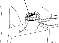
-
Remove the hydraulic-tank cap (Figure 64).
-
Remove the dipstick from the filler neck and wipe it with a clean rag.
-
Insert the dipstick into the filler neck, then remove it and check the fluid level.
Note: The fluid level should be within 6 mm (1/4 inch) of the mark on the dipstick.
-
If the level is low, add the appropriate fluid to raise the level to the FULL mark.
-
Install the dipstick and cap onto the filler neck.
Changing the Hydraulic Filter
| Maintenance Service Interval | Maintenance Procedure |
|---|---|
| After the first 10 hours |
|
| Every 200 hours |
|
Use a genuine Toro replacement filter, Part No. 86-3010.
Important: Using any other filter may void the warranty on some components.
-
Perform the pre-maintenance procedure; refer to Preparing the Machine for Maintenance.
-
Pinch off the hose to the filter-mounting plate.
-
Clean around the filter-mounting area, place a drain pan under the filter, and remove the filter (Figure 65).
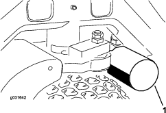
-
Lubricate the new filter gasket and fill the filter with hydraulic fluid.
-
Ensure that the filter mounting area is clean and screw the filter on until the gasket contacts the mounting plate; then tighten the filter 1/2 turn.
-
Release the hose to the filter-mounting plate.
-
Start the engine and let it run for approximately 2 minutes to purge air from the system.
-
Stop the engine and check for leaks.
Changing the Hydraulic Fluid
| Maintenance Service Interval | Maintenance Procedure |
|---|---|
| Every 400 hours |
|
If the fluid becomes contaminated, contact your local Toro distributor to flush the system. Contaminated fluid looks milky or black.
-
Turn the engine off and raise the hood.
-
Disconnect the hydraulic line or remove the hydraulic filter and let the hydraulic fluid flow into a drain pan (Figure 65 and Figure 66).
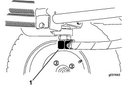
-
Install the hydraulic line when the hydraulic fluid stops draining (Figure 66).
-
Fill the reservoir (Figure 67) with approximately 13.2 L (3.5 US gallons) of hydraulic fluid; refer to Checking the Hydraulic System.
Important: Use only the hydraulic fluids specified. Other fluids could damage the system.
-
Install the reservoir cap.
-
Start the engine.
-
Use all the hydraulic controls to distribute the hydraulic fluid throughout the system, check for leaks, then stop the engine.
-
Check the fluid level and add enough to raise the level to the FULL mark on the dipstick.
Note: Do not overfill.
Checking the Hydraulic Lines and Hoses
| Maintenance Service Interval | Maintenance Procedure |
|---|---|
| Before each use or daily |
|
Check the hydraulic lines and hoses for leaks, kinked lines, loose mounting supports, wear, loose fittings, weather deterioration, and chemical deterioration. Make all necessary repairs before operating the machine.
Cutting Deck Maintenance
Blade Safety
Danger
A worn or damaged blade can break, and a piece of the blade could be thrown at you or bystanders, resulting in serious personal injury or death. Trying to repair a damaged blade may result in discontinued safety certification of the product.
-
Inspect the blade periodically for wear or damage.
-
Never try to straighten a blade that is bent or weld a broken or cracked blade.
-
Replace a worn or damaged blade.
-
Use care when checking the blades. Wrap the blades or wear gloves, and use caution when servicing the blades. Only replace the blades; never straighten or weld them.
-
On multi-bladed machines, take care as rotating 1 blade can cause other blades to rotate.
Separating the Cutting Decks from the Traction Unit
-
Perform the pre-maintenance procedure; refer to Preparing the Machine for Maintenance.
-
Remove the hydraulic-motor-mounting screws and disconnect and remove the hydraulic motor from the deck (Figure 68).
Important: Cover the top of the spindle to prevent contamination.
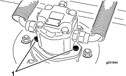
-
Remove the lynch pin or retaining nut securing the deck carrier frame to the lift-arm-pivot pin (Figure 69).
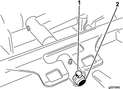
-
Roll the cutting deck away from the traction unit.
Mounting the Cutting Decks to the Traction Unit
-
Perform the pre-maintenance procedure; refer to Preparing the Machine for Maintenance.
-
Move the cutting deck into position in front of the traction unit.
-
Slide the deck-carrier frame onto the lift-arm-pivot pin and secure it with the lynch pin or retaining nut (Figure 69).
-
Using the hydraulic-motor-mounting screws, install the hydraulic motor to the deck (Figure 68).
Note: Ensure that the O-ring is properly positioned and not damaged.
-
Grease the spindle.
Servicing the Blade Plane
The rotary deck comes from the factory preset at 5 cm (2 inches) height-of-cut and blade rake of 7.9 mm (0.31 inch). The left and right heights of cut are also preset to within ± 0.7 mm (0.03 inch) of the other.
The cutting deck is designed to withstand blade impacts without deforming the chamber. If the blade strikes a solid object, inspect the blade for damage and the blade plane for accuracy.
Inspecting the Blade Plane
-
Remove the hydraulic motor from the cutting deck and remove the cutting deck from the tractor.
Note: Use a hoist (or a minimum of 2 people) and place the cutting deck on a flat table.
-
Mark an end of the blade with a paint pen or marker.
Note: Use this end of the blade to check all heights.
-
Position the cutting edge of the marked end of the blade at the 12 o’clock position (straight ahead in the direction of mowing) and measure the height from the table to the cutting edge of the blade (Figure 70).
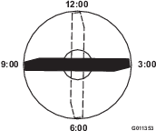
-
Rotate the marked end of the blade to the 3 o’clock and 9 o’clock positions and measure the heights (Figure 70).
-
Compare the 12 o’clock position measured height to the height-of-cut setting.
Note: It should be within 0.7 mm (0.03 inch). The 3 o’clock and 9 o’clock heights should be 3.8 ± 2.2 mm (0.15 ± 0.09 inch) higher than the 12 o’clock setting and within 2.2 mm (0.09 inch) of each other.
If any of these measurements are not within specification, proceed to Adjusting the Blade Plane.
Adjusting the Blade Plane
Start with the front adjustment (change 1 bracket at a time).
-
Remove the height-of-cut bracket (front, left, or right) from the deck frame (Figure 71).
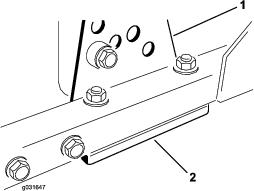
-
Adjust the 1.5 mm (0.06 inch) shims and/or 0.7 mm (0.03 inch) shim between the deck frame and bracket to achieve the desired height of cut (Figure 71).
-
Install the height-of-cut bracket to the deck frame with the remaining shims assembled below the height-of-cut bracket (Figure 71).
-
Secure the socket-head bolt and spacer and flange nut.
Note: The socket-head bolt and spacer are held together with Loctite to prevent the spacer from falling inside the deck frame.
-
Verify the 12 o’clock position setting and adjust if needed.
-
Determine if you need to adjust only 1 or both (right and left side) height-of-cut brackets.
Note: If the 3 o’clock or 9 o’clock side is 3.8 ± 2.2 mm (0.15 ± 0.09 inch) higher than the new front height, then you do not need to adjust for that side. Adjust the other side to within ± 2.2 mm (0.09 inch) of the correct side.
-
Adjust the right and/or left height-of-cut brackets by repeating steps 1 through 3.
-
Secure the carriage bolts and flange nuts.
-
Verify the 12, 3, and 9 o’clock heights.
Servicing the Blade
Removing the Blade
Replace the blade if it hits a solid object, the blade is out of balance, or if the blade is bent. Always use genuine Toro replacement blades to ensure safety and optimum performance. Never use replacement blades made by other manufacturers, because they could be dangerous.
-
Perform the pre-maintenance procedure; refer to Preparing the Machine for Maintenance.
-
Block the cutting deck to prevent it from falling accidentally.
-
Grasp the end of the blade using a rag or thickly padded glove and remove the blade bolt, anti-scalp cup, and blade from the spindle shaft (Figure 72).

-
Install the blade with the sail facing toward the cutting deck, with the anti-scalp cup and blade bolt (Figure 72).
-
Tighten blade bolt to 115 to 149 N∙m (85 to 110 ft-lb).
Inspecting and Sharpening the Blade
-
Perform the pre-maintenance procedure; refer to Preparing the Machine for Maintenance.
-
Block the cutting deck to prevent it from falling accidentally.
-
Examine the cutting ends of the blade carefully, especially where the flat and curved parts of the blade meet (Figure 73).
Note: Because sand and abrasive material can wear away the metal that connects the flat and curved parts of the blade, check the blade before using the machine. If you notice wear, replace the blade; refer to Removing the Blade.
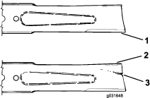
-
Inspect the cutting edges of all the blades, sharpen the cutting edges if they are dull or nicked, sharpen only the top of the cutting edge, and maintain the original cutting angle to ensure sharpness (Figure 74).
Note: The blade remains balanced if the same amount of metal is removed from both cutting edges.

-
To check the blade for being straight and parallel, lay the blade on a level surface and check its ends.
Note: The ends of the blade must be slightly lower than the center, and the cutting edge must be lower than the heel of the blade. This blade produces a good quality of cut and requires minimal power from the engine. By contrast, replace a blade that is higher at the ends than the center or the cutting edge is higher than the heel, because the blade is bent or warped.
-
Install the blade with the sail facing toward the cutting deck, with the anti-scalp cup and blade bolt.
-
Tighten the blade bolt to 115 to 149 N∙m (85 to110 ft-lb).
Checking the Blade Stopping Time
| Maintenance Service Interval | Maintenance Procedure |
|---|---|
| Before each use or daily |
|
The blades of the cutting deck should completely stop in approximately 5 seconds after you shut down the cutting deck.
Note: Ensure that the decks are lowered onto a clean section of turf or hard surface to avoid thrown dust and debris.
To verify the stopping time, have a second person stand back from the deck at least 6 m (20 ft) and watch the blades on 1 of the cutting decks. Shut the cutting decks down and record the time that it takes for the blades to come to a complete stop. If the time is longer than 7 seconds, the braking valve needs adjustment; contact your Toro Distributor for assistance in making this adjustment.
Servicing the Front Roller
Inspect the front roller for wear, excess wobble, or binding. Service or replace the roller or components if any of these conditions exist.
Disassembling the Front Roller
-
Remove the roller-mounting bolt (Figure 75).
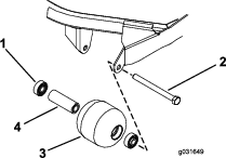
-
Insert a punch through the end of the roller housing and drive the opposite bearing out by alternating taps to the opposite side of inner-bearing race.
Note: There should be a 1.5 mm (0.06 inch) lip of inner race exposed.
-
Push the second bearing out in the press.
-
Inspect the roller housing, bearings, and bearing spacer for damage (Figure 75).
Note: Replace damaged components and assemble the front roller.
Assembling the Front Roller
-
Pressing on the outer race only or equally on the inner and outer race, press the first bearing into the roller housing (Figure 75).
Note: Press on the outer race only or equally on the inner and outer race.
-
Insert the spacer (Figure 75).
-
Pressing on outer race only or equally on the inner and outer race, press the second bearing into the roller housing until it contacts the spacer (Figure 75).
-
Install the roller assembly into the deck frame.
Important: Securing the roller assembly with a gap larger than 1.5 mm (0.06 inch) creates a side load on the bearing and can lead to premature bearing failure.
-
Verify that there is no more than a 1.5 mm (0.06 inch) gap between the roller assembly and the roller-mount brackets of the deck frame.
Note: If there is a gap over 1.5 mm (0.06 inch), install enough 5/8-inch diameter washers to take up the slop.
-
Torque the mounting bolt to 108 N∙m (80 ft-lb).
Storage
Storing the Battery
If you are storing the machine for more than 30 days, remove the battery and charge it fully. Store the battery in a cool atmosphere to avoid quick deterioration of the charge in the battery. To prevent the battery from freezing, make sure that it is fully charged. The specific gravity of a fully charged battery is 1.265 to 1.299.
Preparation for Seasonal Storage
Follow these procedures whenever you store the machine for more than 30 days.
Preparing the Traction Unit
-
Thoroughly clean the traction unit, cutting units, and engine.
-
Check the tire pressure; refer to Checking the Tire Pressure.
-
Check all fasteners for looseness; tighten as necessary.
-
Grease or oil all grease fittings and pivot points; refer to Greasing the Bearings and Bushings.
Note: Wipe up any excess lubricant.
-
Lightly sand and use touch-up paint on painted areas that are scratched, chipped, or rusted.
Note: Repair any dents in the metal body.
-
Service the battery and cables as follows:
-
Remove the battery terminals from the battery posts.
-
Remove the battery.
-
Slowly recharge the battery before storage and every 60 days thereafter for 24 hours to prevent lead sulfation of the battery.
To prevent the battery from freezing, make sure it is fully charged. The specific gravity of a fully charged battery is 1.265 to 1.299.
-
Clean the battery, terminals, and posts with a wire brush and baking-soda solution.
-
Coat the cable terminals and battery posts with Grafo 112X skin-over grease (Toro Part No. 505-47) or petroleum jelly to prevent corrosion.
-
Store the battery on the shelf or on the machine in a cool area. Leave the cables disconnected if you store it on the machine.
-
Preparing the Engine
-
Drain the engine oil from the oil pan and replace the drain plug.
-
Remove and discard the oil filter and install a new oil filter.
-
Fill the oil pan with approximately 3.8 L (4 US qt) of SAE 15W-40 motor oil.
-
Start the engine and run it at idle speed for approximately 2 minutes.
-
Stop the engine.
-
Thoroughly drain all fuel from the fuel tank, fuel lines, fuel filter, and water separator assembly.
-
Flush the fuel tank with fresh, clean diesel fuel.
-
Secure all fuel-system fittings.
-
Thoroughly clean and service the air-cleaner assembly.
-
Seal the air-cleaner inlet and the exhaust outlet with weatherproof tape.
-
Check the anti-freeze protection and add as needed for expected minimum temperature in your area.
Preparing the Cutting Deck
If the cutting deck is separated from the traction unit for any length of time, install a spindle plug in the top of the spindle to protect the spindle from dust and water.