Installation
Determine the left and right sides of the machine from the normal operating position.
Preparing the Machine
-
Remove any attachments.
-
Park the machine on a level surface.
-
Ensure that the loader arms are down on the stops.
-
Shut off the engine, wait for the machine to cool, and remove the key.
-
Relieve hydraulic pressure by pressing the reverse and forward flow hydraulics buttons on the joystick.
-
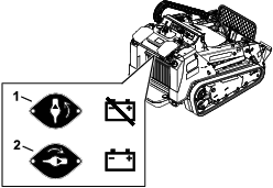
Turn the battery-disconnect switch to the OFF position (Figure 1).
-
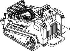
Remove the traction-control plate from the machine by removing the 4 screws holding it in place (Figure 2).
Note: Do not disconnect the traction-control wires and set the plate to the side.
-
Open the rear-access cover; refer to the Operator’s Manual for the machine.
-
Remove the rear screen; refer to Operator’s Manual for the machine.
Installing the Kit
Parts needed for this procedure:
| Replacement pressure switch | 1 |
| Tee fitting (without swivel nut) | 1 |
| Tee fitting (with swivel nut) | 2 |
| Hose (25 inches) | 1 |
| Return hardline | 1 |
| Elbow fitting | 1 |
| Straight fitting | 1 |
| Swivel fitting | 1 |
| Sequence valve | 1 |
| Hose (20-3/4 inches) | 1 |
| Hose (15 inches) | 1 |
Important: You may discard all removed parts unless otherwise noted.
Warning
Seek immediate medical attention if fluid is injected into skin. Injected fluid must be surgically removed within a few hours by a doctor.
-
Ensure that all hydraulic-fluid hoses and lines are in good condition and all hydraulic connections and fittings are tight before applying pressure to the hydraulic system.
-
Keep your body and hands away from pinhole leaks or nozzles that eject high-pressure hydraulic fluid.
-
Use cardboard or paper to find hydraulic leaks.
-
Safely relieve all pressure in the hydraulic system before performing any work on the hydraulic system.
-
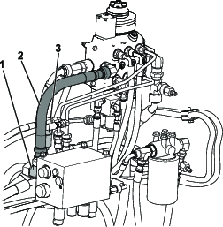
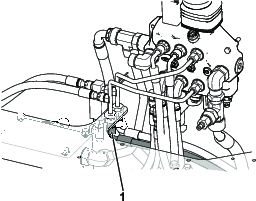
Remove the existing return hose routed from the lift valve to the auxiliary valve (Figure 3).
-
Loosen the existing tee fitting on the auxiliary valve to ease installation of new return hardline.
-
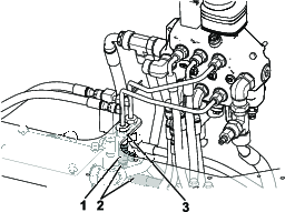
Disconnect the wire harness from the existing pressure switch and remove the switch from the tee fitting.
-
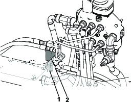
Connect the tee fitting (without swivel nut) onto the pressure switch and keep it loose.
Important: Ensure that the tee fitting side port points to the left of the pressure switch as shown in Figure 4.
-
Install the pressure switch, with the tee fitting connected to it, into the pressure switch tee fitting and torque it to 12 to 15 N∙m (9 to 11 ft-lb). Refer to Figure 4.
-
Ensure that the tee fitting connected to the pressure switch is oriented so that the side port points to the left of the pressure switch as shown in Figure 4. Torque the tee fitting to 46 to 47 N∙m (34 to 42 ft-lb).
-
Remove the right lift-cylinder hose from the rear bulkhead fitting (Figure 5).
-
Connect the tee fitting (with swivel nut) onto the rear bulkhead fitting and torque to 37 to 45 N∙m(27 to 33 ft-lb); refer to Figure 6.
Note: Ensure that the tee fitting side port points to the right as shown in Figure 6.
-
Install the right lift-cylinder hose to the bottom port of the tee fitting and torque to 37 to 45 N∙m (27 to 33 ft-lb); refer to Figure 6.
-
Route the hose (25 inches) in a loop from the tee fitting on the rear lift-cylinder bulkhead to the tee fitting on the bottom of the switch and torque it to 37 to 45 N∙m (27 to 33 ft-lb); refer to Figure 7.
-
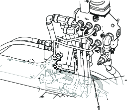
Install new return hardline routing it from the lift valve to the auxiliary valve (Figure 8). Torque the auxiliary-valve end of the hardline to 149 to 184 N∙m (110 to 136 ft-lb) and torque the lift-valve end to 115 to 142 N∙m (85 to 105 ft-lb).
Important: If you previously loosened the tee fitting on the auxiliary valve to ease installation of the new return hardline, torque the tee fitting to 164 to 202 N∙m (121 to 149 ft-lb).
-
Install the 3 fittings onto the sequence valve according to Figure 9 and torque to 27 to 35 N∙m (20 to 26 ft-lb).
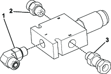
-
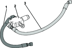
Connect the hose (15 inches) to port 3 on the sequence valve as shown in Figure 10 and torque to 37 to 45 N∙m (27 to 33 ft-lb).
Important: Ensure that the elbow fitting is pointed downward at approximately 45 degrees.
-
Connect the hose (20-3/4 inches) to port 1 on the sequence valve as shown in Figure 10 and torque to 37 to 45 N∙m (27 to 33 ft-lb).
Important: Ensure that the elbow fitting is parallel with the sequence valve.
-
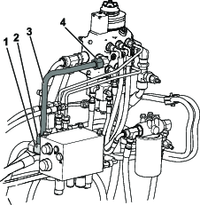
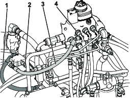
Mount the sequence-valve assembly, port 2, to the hardline saddle fitting as shown in Figure 11and torque to 37 to 45 N∙m (27 to 33 ft-lb).
Important: Ensure that the sequence-valve assembly is oriented parallel to the hardline.
-
Connect the open end of the 15-inch hose to the horizontal port on the tee fitting below the pressure switch (Figure 11). Torque to 37 to 45 N∙m (27 to 33 ft-lb).
-
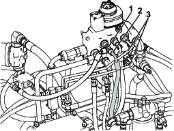
Disconnect the existing hose from the top left port of the lift-valve assembly.
-
Connect the tee fitting (with swivel nut) onto the left top port of the lift-valve assembly as shown in Figure 12 and torque to 37 to 45 N∙m (27 to 33 ft-lb).
Important: Ensure that the tee is pointed downward at approximately 15 degrees to avoid the hose from making contact with the intake chute.
-
Reroute the hose previously removed from the top left port of the lift-valve assembly to the outside of the lift-circuit hardlines (Figure 12) and torque to 37 to 45 N∙m (27 to 33 ft-lb).
-
Connect the open end of the 20-3/4 inch hose to the tee fitting in the lift valve as shown in Figure 12 and torque to 37 to 45 N∙m (27 to 33 ft-lb).
Completing the Installation
-
Install the previously removed rear screen.
-
Close the rear-acess cover.
-
Install the previously removed traction-control plate.
-
Turn the battery-disconnect switch to the ON position (Figure 1).
-
Turn on the machine and extend the arms to get the air out of the system.
-
Check for leaks. Use cardboard or paper to assist in finding hydraulic leaks.
Important: Keep your body and hands away from pinhole leaks or nozzles that eject high-pressure hydraulic fluid.