Installation
Preparing the Machine
-
Park the machine on a level surface.
-
Engage the parking brake.
-
Lower the cutting unit.
-
Shut off the engine and remove the key.
-
Disconnect the battery; refer to the electrical system maintenance section of your Operator’s Manual.
Installing the Seat to the Traction Unit
Parts needed for this procedure:
| Bolt | 4 |
| Nut | 8 |
| Plate | 1 |
| Seat-switch wire harness | 1 |
| Air-ride-seat wire harness (Model No. 31982 only) | 1 |
Positioning the Seat Assembly
-
Remove the console from the seat base and retain the nuts.
Important: Ensure that you support the console after removing it so that it does not crimp or hang by the cables and wires.
-
Install the end of the seat-switch wire harness labeled P2(Seat Switch) to the seat-switch connector under the seat.
-
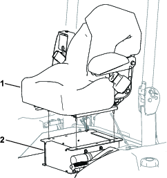
Align the seat studs with the holes in the seat base (Figure 1).
Routing the Wire Harness
Note: Model No. 31980 and 31981 are equipped with 1 wire harness (i.e., the seat-switch wire harness). Model No. 31982 is equipped with 2 wire harnesses (i.e., the seat-switch wire harness and the air-ride-seat wire harness).
-
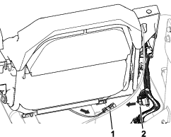
Installing the Seat-Switch Wire Harness:
-
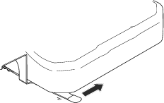
Route the seat-switch harness between the seat and seat base and towards the machine wire harness (Figure 2).
-
Install the end of the seat-switch wire harness labeled P1(Main Harness) to the machine-wire-harness end labeled P11(Seat Switch).
-
-
Installing the Air-Ride-Seat Wire Harness (Model No. 31982 only):
Install the end of the air-ride-seat wire harness to the end of the machine wire harness labeled P08(Opt. Air Ride Seat).
Completing the Installation
-
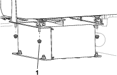
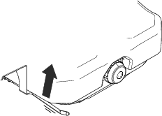
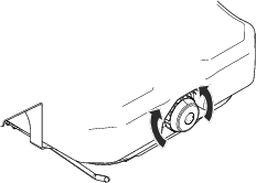
Use 4 nuts to secure the seat to the seat base (Figure 3).
-
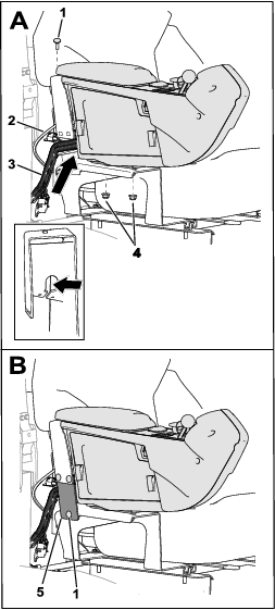
Position the console to the seat bracket (A in Figure 4).
For Model No. 31900, 31901, 31907, and 31909 machines: Ensure that the throttle cable is positioned in the seat-bracket gap above the wire harness (inset of A in Figure 4).
-
Secure the console to the seat bracket with the existing nuts [removed in Positioning the Seat Assembly] and a carriage bolt and nut (A in Figure 4).
Tighten the carriage bolt and nut, then tighten the existing nuts to the console studs.
-
Secure the plate to the seat bracket with 3 carriage bolts and 3 nuts (B in Figure 4).
Connect the Battery
Connect the battery; refer to the electrical system maintenance section of your Operator’s Manual.
Product Overview
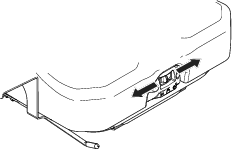
Fore/Aft Locking Lever
Use the fore/aft adjustment lever to change the forward/rearward position of the seat.
-
Model No. 31980: Move the lever to the left (Figure 5), move the seat to a comfortable position, and release the locking lever to secure the position of the seat.
-
Model No. 31981 and 31982: Lift the locking lever to release the seat (Figure 6), move the seat to a comfortable position, and release the locking lever to secure the position of the seat.
Important: The locking lever must secure the operator’s seat at the desired position. The operator’s seat must not move forward or rearward when the seat is locked.
Weight-Adjustment Dial
Adjust the dial (Figure 7) to match your weight (kg or lb).
Suspension-Adjustment Switch
Move the switch (Figure 8) to the left or right to adjust the amount of cushioning.