Introduction

This machine is intended to be used by professional, hired operators in commercial applications. It is primarily designed for transporting, metering and dispersing materials, under a range of moisture conditions, without clogging or drastically affecting the dispersion.

Read this information carefully to learn how to operate and maintain your product properly and to avoid injury and product damage. You are responsible for operating the product properly and safely.

Visit www.Toro.com for product and accessory information, help finding a dealer, or to register your product.

Whenever you need service, genuine Toro parts, or additional information, contact an Authorized Service Dealer or Toro Customer Service and have the model and serial numbers of your product ready. Figure 1 identifies the location of the model and serial numbers on the product. Write the numbers in the space provided.

g014107

This manual identifies potential hazards and has safety messages identified by the safety alert symbol (Figure 2), which signals a hazard that may cause serious injury or death if you do not follow the recommended precautions.

g000502

This manual uses 2 other words to highlight information. Important calls attention to special mechanical information and Note emphasizes general information worthy of special attention.

This product complies with all relevant European directives, for details please see the separate product specific Declaration of Conformity (DOC) sheet.

Electromagnetic Compatibility
Domestic: This device complies with FCC rules Part 15. Operation is subject to the following two conditions: (1) This device may not cause harmful interference and (2) this device must accept any interference that may be received, including interference that may cause undesirable operation.
This equipment generates and uses radio frequency energy and if not installed and used properly, that is, in strict accordance with the manufacturer's instructions, may cause interference to radio and television reception. It has been type tested and found to comply with the limits for a FCC Class B computing device in accordance with the specifications in Subpart J of Part 15 of FCC Rules, which are designed to provide reasonable protection against such interference in a residential installation. However, there is no guarantee that interference will not occur in a particular installation. If this equipment does cause interference to radio or television reception, which can be determined by turning the equipment off and on, the user is encouraged to try to correct the interference by one or more of the following measures:Reorient the receiving antenna, relocate the remote control receiver with respect to the radio/TV antenna or plug the controller into a different outlet so that the controller and radio/TV are on different branch circuits.If necessary, the user should consult the dealer or an experienced radio/television technician for additional suggestions.The user may find the following booklet prepared by the Federal Communications Commission helpful: "How to Identify and Resolve Radio-TV Interference Problems". This booklet is available from the U.S. Government Printing Office, Washington, DC 20402. Stock No. 004-000-00345-4.
FCC ID: OA3MRF24J40MC-BASE, OA3MRF24J40MA-HANDHELD
IC: 7693A-24J40MC-BASE, 7693A-24J40MA-HANDHELD
Operation is subject to the following two conditions: (1) this device may not cause interference, and (2) this device must accept any interference, including interference that may cause undesired operation of the device.

Safety

General Safety

This product is capable of causing personal injury. Always follow all safety instructions to avoid serious personal injury.

  • Read and understand the contents of this Operator’s Manual before using this machine. Ensure that everyone using this product knows how to use it and understands the warnings.

  • Do not put your hands or feet near moving components of the machine.

  • Do not operate the machine without all guards and other safety protective devices in place and working on the machine.

  • Keep the machine away from bystanders while it is moving.

  • Keep children out of the operating area. Never allow children to operate the machine.

  • Park the machine on a level surface; engage the parking brake; shut off the traction-unit engine; remove the key; and wait for all movement to stop before servicing or unclogging the machine.

Improperly using or maintaining this machine can result in injury. To reduce the potential for injury, comply with these safety instructions and always pay attention to the safety-alert symbol Graphic, which means Caution, Warning, or Danger—personal safety instruction. Failure to comply with these instructions may result in personal injury or death.

You can find additional safety information where needed throughout this manual.

Safety and Instructional Decals

Graphic

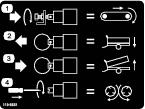
Safety decals and instructions are easily visible to the operator and are located near any area of potential danger. Replace any decal that is damaged or lost.

decal119-6823
decal93-9899
decal119-6838
decal119-0217
decal115-2047
decal93-9852
decal119-6836
decal119-6833
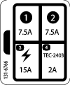
decal131-6766
decal119-6806
decal119-6835
decal119-6869
decal119-6822
decal119-6832
decal119-6812
decal119-6863

Setup

Note: Determine the left and right sides of the machine from the normal operating position.

Installing the Hitch

Parts needed for this procedure:

Bolt, 1 x 6-1/2 inch 2
Locknut, 1 inch 2
  1. Locate and remove the loose parts box shipped on the fender.

  2. Remove the rear support leg from the shipping position and place it in the down position.

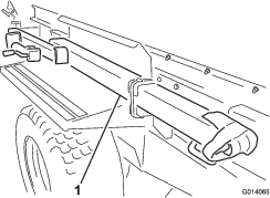
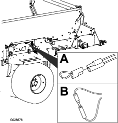
  3. Remove the hitch from the shipping position by cutting both straps securing the hitch to the fender (Figure 3). Remove both mounting brackets from the fender and discard.

    g014065

    Note: Two people are required to remove the hitch assembly.

  4. Slide the hitch tube tongue into place at the front of the machine. Ensure that the jack mounting bracket faces out towards the left side.

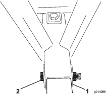
  5. Place a bolt (1 x 6–1/2 inch) through the frame and hitch tube and secure it with a locknut (Figure 4). Torque the locknut to 976 to 1,193 N-m (720 to 880 ft-lb).

  6. Place a bolt (1 x 6–1/2 inch) through the top of the frame and down through the hitch tube and secure it with a locknut (Figure 4). Torque the locknut to 976 to 1,193 N-m (720 to 880 ft-lb).

    g014066
  7. Remove the jack assembly from the rear leg. Install the jack assembly onto the hitch tube, placing the pin horizontally.

    Note: Do not place the pin through the top hole of the jack, or you will not be able to remove the pin when the weight case is secured to the hitch.

Installing the Weight Case

  1. Remove the weights from the weight case.

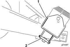
  2. Remove the bolts (1/2 x 5-1/2 inch) from the mounting bracket holding the weight case. Discard the mounting brackets (Figure 5).

    g014067
  3. Position the weight case on the hitch, as far forward as possible.

  4. Mount the weight case to the hitch with 2 bolts (1/2 x 5-1/2 inch) and locknuts. Torque the locknuts to 91 to 112 N-m (67 to 83 ft-lb).

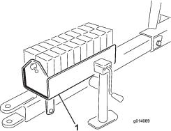
  5. Fill the weight case with the weights and install the bar and pin (Figure 6).

    g014069

Adjusting the Mirror

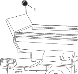
Adjust the mirror (Figure 7) so when the operator is seated he or she can view the inside of the hopper.

g015149

Attaching the Hydraulics to the Tow Vehicle

Note: The tow vehicle must be equipped with an open center auxiliary hydraulic valve.

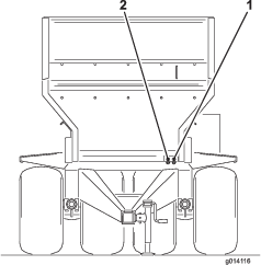
Connect the two hydraulic hoses from the machine to the tow vehicle. Facing the front of the machine, connect the right hose to the pressure side and the left hose to the return side (Figure 8). The return hose has an in line one way check valve. Also, there is an arrow on the check valve which should face toward the tow vehicle.

g014116

Important: Do not allow the hydraulic hoses and the power cable to drag on the ground when operating the machine. Avoid locations where they could become pinched or cut.

Installing the Wiring for the Tow Vehicle

Parts needed for this procedure:

SH Pendant (model 444931)1
SH Wire harness (model 44931)1
EH Wire harness (model 44954)1
Bracket (model 44954)1
Bolt, 5/16 x 1 inch (model 44954)2
Nut, 5/16 inch (model 44954)2
Bolt, 1/4 x 1 inch (model 44954)2
Nut, 1/4 inch (model 44954)2

SH Models

  1. Run the battery wiring harness through the tow vehicle and up to the battery.

  2. Connect the fused wire to the positive connector and the other wire to the ground to the battery.

  3. Attach the SH battery wiring harness to the solenoid wiring harness coming from the base unit. The connector is located among the hydraulic hose attached to the tow vehicle.

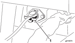
  4. On SH models plug the on/off pendant switch (4 prong end) into the socket at the front left corner of the machine (Figure 9).

    g014074
  5. Ensure that all the hose connections and wire harnesses are installed correctly and tightened.

    Important: Always remove the on/off pendant switch cord or disconnect the power supply wire when the machine and tow vehicle are not in use. Otherwise, the tow vehicle battery will lose power.

EH Models

  1. Mount the socket bracket to the rear of the tow vehicle with 2 bolts (5/16 x 1 inch) and nuts.

  2. Route the wire harness connector through the hole to the socket. Slide the boot down the harness if the connector does not go through the hole.

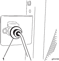
  3. Secure the wire harness socket to the bracket with 2 bolts (1/4 x 1 inch) and nuts (Figure 10).

  4. Connect the fused wire to the positive connector and the other wire to the ground to the battery.

  5. Attach the base unit wiring harness to the tow vehicle wiring harness (Figure 10). The connector is located among the hydraulic hose attached to the tow vehicle.

    g014100
  6. Ensure that all the wire harnesses are installed correctly and tightened.

Installing the Tow Vehicle Brake Components

Parts needed for this procedure:

Foot controller 1
Brake controller 1
Harness assembly1
Socket bracket 1
Screw, 5/16 x 1 inch4
Nut, 5/16 inch4
Wire splices 6
Cable tie 10
Bolt, #10 x 7/8 inch2
Nut, #102
Hose clamp1

Note: Lay out the harness on the tractor to determine the mounting locations of the harness components. Cable ties are supplied to retain any surplus cable lengths. Also, wire splices are provided if the length of the harness have to be altered (shortened or lengthened). Heat the shrink connectors until they shrink tight onto the wires.

Important: If length is added to the harness, make sure to use the proper gauge wire.

  1. Mount the socket bracket to the rear of the tow vehicle with 2 bolts (5/16 x 1 inch) and nuts.

  2. Route the wire harness connector through the hole to the socket. Slide the boot down the harness if the connector does not go through the hole.

  3. Bolt the wire harness, with the socket connector, to the rear of the socket bracket with 2 bolts (5/16 x 1 inch) and nuts.

  4. Route the harness along the tow vehicle.

  5. Mount the brake controller to the tractor dash or the fender with the 2 bolts (#10 x 7/8 inch) and nuts (#10).

  6. Using the hose clamp, secure the foot controller to the pad on the tow vehicle brake pedal.

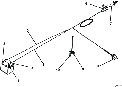
  7. Connect the harness to the components (Figure 11) as follows:

    1. Plug the shorter wire from the harness into the foot controller wire connector.

    2. Connect the longer wire from the harness to the brake controller wire connector.

    3. Select one of the following procedures when connecting the ring terminal wire, with the fuse, to the positive battery terminal.

      • To have the brake controller powered only when the tow vehicle is on, attach the ring terminal wire, with the fuse, to an open auxiliary power source that has a rating of 15A or more. Use a 10A fuse for a 2 wheel brake system and a 15A fuse for a 4 wheel brake system.

        Note: The ring terminal may need to be removed and a different terminal end may need to be attached to match the auxiliary power source connection.

      • To have the brake controller always powered, attach the ring terminal wire, with the fuse, to the positive battery terminal.

        Note: If the tow vehicle is to be stored for an extended period, remove the fuse from the brake controller wire harness or disconnect the wire harness from the brake controller. This will prevent the battery from being drained

    4. Connect the other ring terminal wire, without the fuse, to the negative (-) battery terminal.

    g021113
  8. Secure the rubber boot to the connector and to the wire harness with a cable tie.

  9. Secure all loose harness wires with cable ties.

  10. A 10 amp fuse is included in the harness. If using a 4 wheel brake kit, replace the 10 amp fuse with the provided 15 amp fuse.

Setting the Electric Brake Adjustments

Before operating the machine for the first time, the electric brakes must be synchronized to the tow vehicle’s brakes (so that they operate at the same time).

The machine and the tow vehicle will seldom have the correct amperage flow to the brake magnets to provide comfortable, safe braking. Changing the load weight, as well as uneven alternator and battery output, can result in unstable current flow to the brake magnets.

The Brake Control compensates for trailer load variations by limiting the maximum torque output of the brakes by adding dropping resistance in the electrical control line. When towing a trailer loaded to brake rated capacity, the Brake Control must be set at maximum braking. When pulling an empty or partially loaded trailer, the Brake Control must be set between maximum and minimum braking at a position just before the point at which trailer tire skidding occurs when actuating the hand control fully on. Failure to install and use the Electric Brake Control will result in excessive brake torque when stopping a trailer loaded to less than brake capacity.

Assembling the Handheld Remote (Model 44954 only)

Parts needed for this procedure:

Handheld remote1
AA batteries4
Magnetic bracket1
Screws, small6
  1. Remove the rubber bands securing the remote halves together, and remove the back cover.

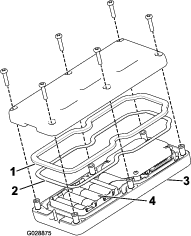
  2. Plug each battery into a terminal cradle observing proper polarity. (If the batteries are improperly installed, the unit will not be damaged, but it will fail to operate.) The cradle is embossed with polarity markings for each terminal (Figure 12).

    g028875
  3. Ensure that the steel gasket and rubber seal are seated in the channel in the remote and set the back cover in place (Figure 12).

  4. Secure the cover with 6 screws (Figure 12) and torque them to 1.5 to 1.7 N-m (13 to 15 in-lb).

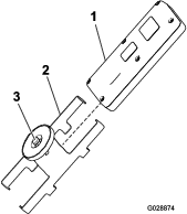
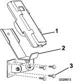
  5. Install the handheld remote into the magnetic remote bracket, slide the halves together to secure the remote, and tighten the bolt in the magnet (Figure 13).

    g028874

Installing the EH Wireless Control Mounting Bracket On the Tow Vehicle (Model 44954 only)

Parts needed for this procedure:

Mounting bracket assembly1
Backing plate1
Flange head bolt, 5/16 x 1-1/2 inch4
Flange head locknut, 5/164
  1. For Tow Vehicle mounting, determine an appropriate location for the handheld remote mounting bracket. The surface should be flat and solid.

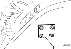
  2. Using the backing plate as a template, locate, mark, and drill 4 holes (11/32 inch diameter) in the tow vehicle mounting surface.

  3. Attach the mounting bracket and backing plate with 4 flange head bolts (5/16 x 1-1/2 inch) and flange locknuts (Figure 14 and Figure 15).

    g028873
    g014103

Product Overview

Hydraulic Control Valves (SH Models)

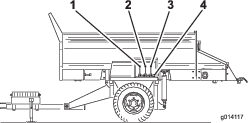
g014117

Left Valve

The left valve controls the machine conveyor belt direction (Figure 16).

Center Valve

The center valve raises and lowers the machine (Figure 16).

Right Valve

The right valve controls the option (Figure 16).

Option Hydraulic Quick Connectors

Connect the option hydraulic here (Figure 16).

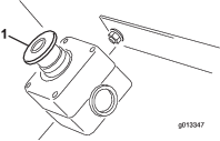
E-Stop button

When finished working with the machine, always press the E-STOP button (Figure 17) to disable the electrical system. When beginning work with the machine you must pull the E-STOP button back out before turning on the handheld remote.

g013347

Diagnostic LED Function (EH Models)

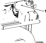
After you pull up the E-STOP button, the diagnostic LED (Figure 18) will illuminate and remain on for 5 seconds, turn off for 5 seconds, and then will begin flashing at 3 Hz (3 flashes a second) until you turn the handheld remote on. If the light turns on for 5 seconds and then starts blinking at 10 Hz (with or without a 5 second pause), there is a fault with the machine; refer to Checking Fault Codes (EH Models Only).

Note: If you had the handheld remote on when you pulled up the E-STOP button, the light will not flash at 3 Hz (3 flashes per second) after turning off for 5 seconds.

g028964

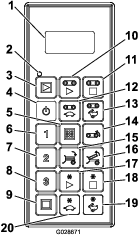
Handheld Remote (EH Models)

g028671
Weight1,721 kg (3,794 lb)
Handheld Remote Specifications 
Handheld Unit Operating Temperature Range -20°C to 55°C (-4°F to 131°F)
Handheld Unit Storage Temperature Range-4°F to 131°F-20°C to 55°C (-4°F to 131°F)
Base Unit Operating Temperature Range-20°C to 70°C (-4°F to 158°F)
Base Unit Storage Temperature Range-40°C to 185°C (-40°F to 185°F)
Humidity0 to 100%
VibrationIEC60068-2-6 10Hz TO 150Hz @ 1.0g Peak Acceleration
Shock10g Peak Shock Acceleration
Radio 
Frequency2.4 GHz
ModulationDirect Sequence Spread Spectrum
AntennaExternal
Power 
Handheld Unit Power Source4 x Type AA Alkaline
Base Unit Power12–14.4 VDC

Attachments/Accessories

A selection of Toro approved attachments and accessories are available for use with the machine to enhance and expand its capabilities. Contact your Authorized Service Dealer or Distributor or go to www.Toro.com for a list of all approved attachments and accessories.

Operation

Before Operation

Before Operation Safety

  • The machine has different balance, weight, and handling characteristics compared to some other types of towed equipment. Read and understand the contents of this Operator's Manual before operating the machine. Become familiar with all controls and know how to stop quickly.

  • Never allow children to operate the machine. Do not allow adults to operate the machine without proper instructions. Only trained and authorized persons should operate this machine.

  • Keep all shields and safety devices in place. If a shield, safety device or decal is illegible or missing, repair or replace it before operating the machine.

  • The machine is designed only for off-road use. The maximum recommended speed is 24 km/h (15 mph) without a load and 13 km/h (8 mph) with a full load.

  • Tighten any loose nuts, bolts, and screws to ensure that the machine is in safe operating condition. Ensure that the machine tongue mounting pins, hitch pins, and tongue jack are in place and secure.

  • Do not modify this equipment in any manner.

  • The tongue is the area on the machine where the hitch connects to the tow vehicle. The weight of the tongue affects the stability of the machine.

    • A negative or positive tongue weight can cause injury when connecting or disconnecting the machine to the tow vehicle. When installed, ensure that the jack-stands are properly engaged.

    • When the weight of the tongue is forced up into the hitch of the tow vehicle, this produces a negative tongue weight.

      Negative tongue weight may also result when attachments are mounted on the rear of the machine.

    • When the weight of the tongue is forced down onto the hitch of the tow vehicle, this produces a positive tongue weight.

  • Never attach the machine to or remove the machine from the traction unit if there is material in the hopper. The tongue may flip up, causing injury.

Connecting the Machine to the Tow Vehicle

  1. Connect the machine hitch to the tow vehicle using a 25 mm (1 inch) diameter safety approved hitch pin and safety clip (not supplied).

    Important: Use a high strength hitch pin that is approved for tow vehicle hitches.

  2. Adjust the hitch height by turning the jack stand handle to keep the machine level.

  3. Lower the hitch using the jack stand.

  4. When the full weight of the machine has been transferred to the tow vehicle’s draw bar from the jack stand, pull the pin holding the jack stand in place.

  5. Turn the jack stand 90 degrees counter clockwise until the bottom of the jack stand points to the rear of the machine. This is the traveling position.

    Caution

    Raise the jacks into the traveling position before towing the machine.

  6. Connect the two hydraulic hoses from the machine to the tow vehicle. Facing the front of the machine, connect the right hose to the pressure side and the left hose to the return side (Figure 20). The return hose has an in line one way check valve. The arrow on the check valve should face the tow vehicle return connector.

    g014116

    Important: Do not allow the hydraulic lines, the power cable, and the pendant cables to drag on the ground during operation. Avoid locations where they could become pinched or cut.

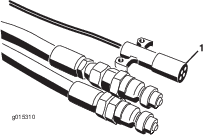
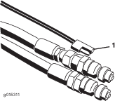
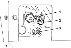
  7. Connect the power harness to the tow vehicle (Figure 21 and Figure 22). On SH models place the on/off pendant within reach of the driver’s seat. Ensure that the switch is off.

    g015310
    g015311
  8. Connect the coiled, power cable to the socket on the machine and the tow vehicle (Figure 11).

  9. Check the hydraulic oil level in the tow vehicles tank and add more to fill it, if necessary. (See the tow vehicle’s Owner’s Manual).

  10. Test the hydraulics before operating the machine for the first time.

  11. Set the electric brake (if so equipped) as follows:

    • Before operating the machine for the first time, the electric brakes must be synchronized to the tow vehicle’s brakes (so that they operate at the same time).

    • The machine and the tow vehicle will seldom have the correct amperage flow to the brake magnets to provide comfortable, safe braking. Changing the load weight, as well as uneven alternator and battery output, can result in unstable current flow to the brake magnets.

    • The Load Control compensates for trailer load variations by limiting the maximum torque output of the brakes by adding dropping resistance in the electrical control line. When towing a trailer loaded to brake rated capacity, the Brake Control must be set at maximum braking. When pulling an empty or partially loaded trailer, the Brake Control must be set between maximum and minimum braking at a position just before the point at which trailer tire skidding occurs when actuating the hand control fully on. Failure to install and use the Electric Brake Control will result in excessive brake torque when stopping a trailer loaded to less than brake capacity.

    Caution

    If you hear a noise from the tow vehicle hydraulics and the machine controls do not operate, the hoses have been connected incorrectly and must be reversed.

    Note: You may have to relieve the pressure in the hoses of the machine connecting to the tow vehicle, to ensure a completed connection.

    Important: When making sharp turns, the hydraulic hoses may contact the tow vehicle wheels. Avoid making sharp turns, if necessary, use a bungee cord (a rubber strap with hooks on both ends) to pull back the hoses toward the center.

Loading Material

Load the machine from the top or from the rear.

For most materials, such as sand or gravel, you can use a front end bucket loader. For materials such as landscaping ties or fertilizer bags, load from the rear by placing the material on the conveyor belt and setting the hydraulics in the load position.

You may need to remove the rear gate for easier access.

If sacks of material are being used, empty the sacks into the loader’s bucket before loading the material into the hopper. To ensure stability, distribute the load evenly, front to back and side to side.

During Operation

During Operation Safety

  • The owner/operator can prevent and is responsible for accidents that may cause personal injury or property damage.

  • Do not operate the machine when tired, ill, or under the influence of alcohol or drugs.

  • Use your full attention while operating the machine. Do not engage in any activity that causes distractions; otherwise, injury or property damage may occur.

  • Wear appropriate clothing, including eye protection; long pants; substantial, slip-resistant footwear; and hearing protection. Tie back long hair and do not wear loose clothing or loose jewelry.

  • Never carry passengers on the machine and keep bystanders and pets away from the machine during operation.

  • Keep your hands and feet out of the hopper while the machine is operating, or while the engine is running on the tow vehicle.

  • Remain seated whenever the tow vehicle is in motion.

  • Using the machine demands attention. Failing to operate tow vehicle safely may result in an accident, tip-over of the tow vehicle, and serious injury or death. Drive carefully, and to prevent tipping or loss of control, do the following:

    • Use extreme caution, reduce the speed, and maintain a safe distance (twice the width of the machine) around sand traps, ditches, water hazards, ramps, unfamiliar areas, or other hazards.

    • Reduce the speed of a loaded machine when negotiating terrain undulations to avoid causing the machine to become unstable.

    • Watch for holes or other hidden hazards.

    • Use caution when operating on a slope. Travel straight up and down slopes. Reduce speed when making sharp turns or when turning on hillsides. Avoid turning on hillsides whenever possible.

    • Use extra caution when operating on wet surfaces, at higher speeds or with a full load. Stopping time increases with a full load. Shift into a lower gear before starting up or down a hill.

    • Avoid sudden stops and starts. Do not go from reverse to forward or forward to reverse without coming to a complete stop.

    • Do not attempt sharp turns or abrupt maneuvers or other unsafe driving actions that may cause a loss of control.

    • Be aware of your surroundings when turning or backing up the machine. Ensure that the area is clear and keep all bystanders out of the operating area. Proceed slowly.

    • Watch out for traffic when near or crossing roads. Always yield the right of way to pedestrians and other vehicles. Obey all traffic rules and check for local regulations on the operation of the machine on or near highways.

    • Always watch out for and avoid low overhangs such as tree limbs, door jambs, overhead walkways, etc. Ensure that there is enough room over head to easily clear the tow vehicle and your head.

    • Do not operate the machine when there is the risk of lightning.

    • If you are ever unsure about safe operation, stop working and ask your supervisor.

    • Do not leave the machine unattended while it is running.

  • Ensure that the machine is connected to the tow vehicle before loading.

  • Do not carry loads that exceed the load limits of the machine or the tow vehicle.

  • The stability of loads can vary—for example, high loads have a higher center of gravity. Reduce the maximum load limits to ensure better stability, if necessary.

  • To avoid causing the machine to tip over, do the following:

    • Carefully monitor the height and weight of the load. Higher and heavier loads can increase the risk of tipping.

    • Distribute the load evenly, from front to back and side to side.

    • Be careful when turning and avoid unsafe maneuvers.

    • Always ensure that the machine is connected to the tow vehicle before loading.

    • Do not put large or heavy objects into the hopper. This could damage the belt and rollers. Also ensure that the load has a uniform texture. Small rocks in the sand can become projectiles.

  • Do not stand behind the machine when unloading or spreading. The optional twin spinner, cross conveyor, and processor can eject particles and dust at a high speed.

  • Unload the machine or disconnect it from the tow vehicle while on a level surface.

  • Ensure that the machine is connected to the tow vehicle before unloading.

  • Do not travel with the machine in the fully raised position. This increases the risk of tipping over the machine.

  • The machine has a safe range for traveling with attachments as shown by the green section in the decal.

  • Do not travel with the machine in the caution range (yellow/black). When there are no attachments on the machine, travel with the machine in the lowered position.

  • Shut off the machine when approaching people, vehicles, vehicle crossings, or pedestrian crossings.

  • Do not operate the machine with the weight case removed or out of position.

  • When equipped, hydraulic trailer brakes may overheat the fluid in the hydraulic circuit if the brakes remain activated continuously. Always use a lower speed gear selection when descending long hills. Activate the brakes intermittently to allow for cooling cycles for both the vehicle and the topdresser.

Slope Safety

  • Slopes are a major factor related to loss of control and rollover accidents, which can result in severe injury or death. You are responsible for safe slope operation. Operating the machine on any slope requires extra caution. Before using the machine on a slope, do the following:

  • Evaluate the site conditions to determine if the slope is safe for machine operation, including surveying the site. Always use common sense and good judgment when performing this survey.

  • Review the slope instructions listed below for operating the machine on slopes and to determine whether you can operate the machine in the conditions on that day and at that site. Changes in the terrain can result in a change in slope operation for the machine.

  • Use extreme caution when traveling on hills, especially when turning.

    • Traveling across hills with the machine could result in a tip-over, or a loss of traction for the traction unit or the machine.

    • Always travel straight up and down hills—do not travel sideways or diagonally. When traveling down a hill, do not exceed the speed at which you can travel up the same hill. Stopping distance increases when traveling down hills.

    • Reduce the weight of the load when traveling on steep hills and avoid piling the load high.

  • Identify hazards at the base of the slope. Use extreme caution when operating the machine near drop-offs, ditches, embankments, water, or other hazards. The machine could suddenly roll over if a wheel goes over the edge or the edge collapses. Keep a safe distance (twice the width of the machine) between the machine and any hazard.

  • Remove or mark obstacles such as ditches, holes, ruts, bumps, rocks, or other hidden hazards. Tall grass can hide obstacles. Uneven terrain could overturn the machine.

  • Avoid starting, stopping, or turning the machine on slopes. Avoid making sudden changes in speed or direction; turn slowly and gradually.

  • Do not operate a machine under any conditions where traction, steering, or stability is in question. Be aware that operating the machine on wet grass, across slopes, or downhill may cause the machine to lose traction. Loss of traction to the drive wheels may result in sliding and a loss of braking and steering. The machine can slide even if the drive wheels are stopped.

  • Be aware that operating the machine on wet grass, across slopes, or downhill may cause the machine to lose traction. Loss of traction to the drive wheels may result in sliding and a loss of braking and steering.

  • Always keep the traction unit in gear when going down slopes. Do not coast downhill (applicable only to gear-drive units).

Turning the Machine Power On/Off

When finished working with the machine, always press the E-STOP button (Figure 23) to disable the electrical system. When beginning work with the machine, you must pull the E-STOP button back out before turning on the handheld remote.

g013347

Important: When done operating the machine, press the E-STOP button to prevent the tow vehicle battery from being discharged.

Operating the Hydraulic Control Valves on SH Models

There are three hydraulic control valves located on the left fender of the machine (Figure 24).

g014117

Note: Return all control valve handles to their center position after use to avoid unintended starting.

Left Valve

The left valve controls the machine conveyor belt direction.

  • To unload the machine, pull the control lever toward you. This moves material to the rear along the conveyor belt.

  • To load the machine, push the control lever away from you. This moves material to the front along the conveyor belt.

  • To stop the conveyor belt, move the control lever to the center position.

Center Valve

The center valve raises and lowers the machine.

  • To raise the machine, pull on the control lever until the desired height is reached, then release it.

  • To lower the machine, push on the control until the desired height is reached, then release it.

    Caution

    Do not keep holding the control lever in the raised or lowered position once the lift cylinders have reached their maximum travel position.

Right Valve

The right valve controls the option.

  • To turn on the option, pull on the control lever.

  • To turn off the option, return the control lever to the center position.

    Warning

    Pushing the control lever does not have any function. Options cannot be reversed.

    Important: Do not pull the option lever into the On position without an option mounted. This can damage the floor motor and stop the machine.

Operating the Hydraulic Controls and Options on EH Models

Remote Control System

The remote control system consists of a handheld remote, a +12 to +14.4 VDC Base Unit, and a wiring harness. The system is specifically designed to be used with and to control a MH-400 Material Handler.

Handheld Remote

g028671

Button Functions

ButtonNamePrimary Function
GraphicON/OFFPower the remote on and off.
GraphicALL STARTProvides functional control on both the Floor and Option including on/off and displaying the speed.
GraphicFLOOR STARTProvides functional control of the hopper conveyor floor belt including on/off and displaying the floor speed.
GraphicFLOOR STOPStops the Floor.
GraphicFLOOR DECDecreases the Floor speed.
GraphicFLOOR INCIncreases the Floor speed.
GraphicFLOOR REVERSEMomentary button that reverses the floor direction. Reverse floor speed can be modified using the FLOOR INCREASE and FLOOR DECREASE SPEED buttons while pressing the FLOOR REVERSE button. Upon release of the FLOOR REVERSE button, the floor turns off.
GraphicTILT BED DOWNMomentary button for lowering the bed.
GraphicTILT BED UPMomentary button for raising the bed.
GraphicGraphicGraphicPRESET 1Three separate preset values may be stored for both floor and option speeds.
GraphicSTOREUsed in conjunction with the PRESET button to store or establish a preset memory.
GraphicOPTION STARTProvides functional control of the rear option including on/off and displaying the option speed.
GraphicOPTION STOPStops the option.
GraphicOPTION DECDecreases the option speed.
GraphicOPTION INCIncreases the option speed.
GraphicALL STOPStops both floor and option.

Turning On the Handheld Remote

Press the ON/OFF button on the remote and wait for the it to find the base. Ensure that there are no buttons being pressed on the hand held while it is performing its start up routine.

Manual Override (Model 44594)

Should the remote ever be lost, damaged or fail, the machine functions and operation are still possible in order to complete tasks or continue work until the problem is resolved.

The override access is on the driver side of the hydraulic system (Figure 26).

g297178
  • To adjust the floor speed (Figure 26), turn the knob clockwise. Maximum floor speed is used in the Color-Coded Operating System so this adjustment can be made while no hydraulic flow is present. This is most relevant when you have a hopper full of sand.

    decal119-6832
  • To raise the hopper (Figure 26), push in on the ring on the valve stem.

  • To lower the hopper (Figure 26), pull out on the ring on the valve stem.

  • To adjust the spinner speed (Figure 26), use a flat-head screwdriver to increase by turning clockwise or decrease by turning counter clockwise.

Note: If adjusting with the hydraulic flow active, ensure that the floor is turned off if you do not wish to have sand being spread as you adjust.

Once your settings are acceptable, use the hydraulic flow control on your tow vehicle to turn the system on and off for operation.

Key Functionality Elements

  • When the handheld remote is first powered on, the display should read FLR OFF and OPT OFF in approximately 5 seconds. If the words “waiting for base” are in the display, check to ensure there is electrical power to the base unit and ensure the E-STOP button on the base unit is pulled out.

  • There is always a current working memory. This is not the same as a preset. The last saved work settings will be in the current working memory when the handheld remote is powered on.

  • Operational sequence of the handheld remote start buttons:

    • Pressing a start button once (ALL START, FLOOR START, or OPTION START) calls up the current working memory setting stored in the handheld remote.

    • By pressing the same start button a second time the component turns on if the hydraulics are engaged (it shows numbers ramping up in the display).

    • Pressing the same start button a third time will store the new setting established in the remote’s working memory.

  • After pressing a start button once to view the current working memory setting in a non-working mode, there is approximately 10 seconds to begin adjusting the setting or the element will revert back to off. In a working mode, the 10 second rule is gone.

  • To program a preset, the key to remember is the elements must be activated or engaged.

  • To operate from a preset, the element speed percentages must be in the display to activate or engage them. If the words OFF are in the display, the preset must be recalled.

Manually Overriding the Hydraulic Controls

EH Models

If the handheld remote is missing, damaged, or fails, you can still operate the machine to complete tasks or continue a spreading job.

Preparing the Machine

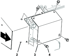
  1. At the right side of the machine, remove the 4 flange-head capscrews that secure the cover plate to the override cover (Figure 28).

    g285427
  2. Ensure that the parking brake is engaged, start the traction unit, and supply hydraulic pressure to the machine.

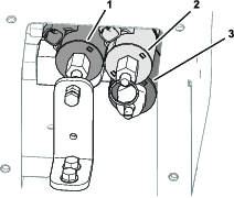
  3. Locate the 3 control valves (Figure 29).

    g285426

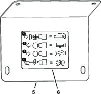
    Note: Refer to the decal located on the cover plate (Figure 30).

    g285596

Adjusting the Floor Speed

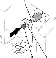
  1. Loosen the jam nut at the manual-override bracket (Figure 31).

    g285594
  2. Rotate the hex-head screw for the valve override clockwise to increase the floor speed (Figure 31).

    Note: Use the maximum-floor speed of the color-coded operation system when you have no hydraulic flow. This setting is also helpful when the hopper is full of sand.

  3. When the machine is running at the correct floor speed, tighten the jam nut.

Adjusting the Position of the Hopper

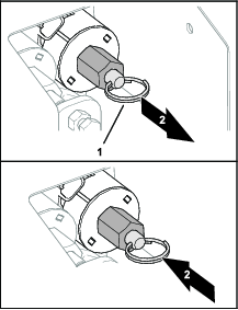
  • To lower the hopper (Figure 32), pull the ring on the valve stem.

    g285595
  • To raise the hopper (Figure 32), push the split ring on the valve stem.

Adjusting Accessory Attachment Speed

  1. Rotate the hex-head screw for the valve override clockwise to increase the floor speed (Figure 33).

    Note: If you are adjusting the machine with the hydraulic flow active and do not want sand spread as you adjust, ensure that the floor is turned off.

    g285593
  2. Once your settings are acceptable, use the hydraulic flow control on your tow vehicle to turn the system on and off during operation.

Resetting Manually Overridden Hydraulic Controls

EH Models

If you found, repaired, or replaced the handheld remote, reset the floor-speed solenoid, attachment-speed solenoid, or both before controlling the machine with the handheld remote.

Reset the Floor-Speed Solenoid

EH Models
  1. Loosen the jam nut at the manual-override bracket (Figure 34).

    g285597
  2. Rotate the hex-head screw for the valve override counter clockwise until you see a small gap between the end of the screw and the end of the stem of the floor-speed solenoid (Figure 34).

  3. Tighten the jam nut (Figure 34).

Reset the Attachment-Speed Solenoid

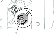
Rotate the flat-head screw counterclockwise until the valve in the solenoid is fully open (Figure 35).

g285593

Installing the Cover Plate

Secure the cover plate to the override cover with the 4 flange-head capscrews (Figure 36).

g285427

Using the Liquid Crystal Display (LCD)

The 2 line, 8 character-per-line LCD (Liquid Crystal Display) shows status and activity as the remote buttons are pressed. It features user adjustable backlighting and contrast. Changes are saved in the remote current working memory. When the unit is turned on after being powered down, the last settings for contrast and backlighting are used for the display.

To Increase the Contrast:

Hold the ALL STOP and the OPTION INCREASE buttons simultaneously while observing the display until the contrast is as desired.

Graphic + Graphic

Note: There are three settings: OFF, LOW, and HIGH.

To Decrease the Contrast:

Hold the ALL STOP and the OPTION DECREASE buttons simultaneously while observing the display until the contrast is as desired.

Graphic + Graphic

Note: There are three settings: OFF, LOW, and HIGH.

To Increase the Backlighting:

Hold the ALL STOP and the FLOOR INCREASE buttons simultaneously while observing the display until the backlighting is as desired.

Graphic + Graphic

Note: There are three settings: OFF, LOW, and HIGH.

To Decrease the Backlighting:

Hold the ALL STOP and the FLOOR DECREASE buttons simultaneously while observing the display until the backlighting is as desired.

Graphic + Graphic

Note: There are three settings: OFF, LOW, and HIGH. Backlighting consumes the most energy of all Handheld Remote functions. Increasing the backlighting increases power consumption and will shorten the life span of the batteries; the lower the backlighting, the longer the battery life span.

Understanding the Remote Status LED

The remote status LED blinks slowly at 2 Hz (twice per second) when the handheld remote is transmitting but no buttons are being pressed, when the floor and option buttons active. When you press a button, the light will blink at 10 Hz.

Replacing the Remote Batteries

The handheld remote is powered by 4, AA Alkaline batteries (1.5 V each) and operates between 2.4 to 3.2 V. Battery life is approximately 300 hours (continuous operation with the backlight off), but battery life longevity is affected by usage factors, particularly backlight intensity setting—the higher the backlight setting, the more power consumed resulting in shorter battery life.

Important: Keep fresh spare batteries at hand at all times that the system is in use.

  1. Loosen the bolt in the magnet on the magnetic remote bracket (Figure 37).

    g028874
  2. Slide the bracket sides apart and remove the remote (Figure 37).

  3. Remove the 6 screws from the back of the remote and remove the cover (Figure 38).

    Note: If possible, leave the rubber seal and steel gasket in the channel when removing the cover and batteries.

    g028875
  4. Remove the discharged batteries and properly dispose in accordance with local regulations.

  5. Plug each fresh battery into a terminal cradle observing proper polarity. (If the batteries are improperly installed, the unit will not be damaged, but it will fail to operate.) The cradle is embossed with polarity markings for each terminal (Figure 38).

  6. If you accidentally removed the rubber seal and the steel gasket, replace them carefully into the channel in the handheld remote (Figure 38).

  7. Replace the cover and secure it with the 6 screws removed previously (Figure 38) and torque them to 1.5 to 1.7 N-m (13 to 15 in-lb).

  8. Install the handheld remote into the magnetic remote bracket, slide the halves together to secure the remote, and tighten the bolt in the magnet (Figure 37).

Caring for the Handheld Remote

Though the handheld remote is rugged, care should be taken not to drop the unit onto hard surfaces. To clean it, use a soft cloth moistened with water or a mild cleaning solution to wipe it paying particular attention to avoid scratching the LCD screen.

Associating the Handheld Remote with the Base

The factory initially associates the remote to the base allowing them to communicate; however, there may be instances in the field when you must reassociate a remote and a base unit, as follows:

  1. Press the E-Stop button to remove power from the base unit and make sure the handheld is off.

  2. Stand near the base unit in clear line of sight.

  3. Simultaneously press and continue to hold the ON/OFF and the ALL STOP buttons.

    Graphic + Graphic

    The handheld remote goes through its initialization screens and settles on ASSOC PENDING.

  4. Continue to hold both buttons and then quickly release them when ASSOC ACTIVE is displayed (approximately 4 seconds).

    The display will show PRESS STORE.

  5. Press and hold the STORE button.

    Graphic

    The remote displays POW UP BASE.

  6. While continuing to hold the STORE button, pull out on the E-STOP button to power up the base unit.

    The handheld remote will associate (link) with the base unit. Upon success, the display will show ASSOC PASS.

  7. Release the STORE button.

Important: If the display shows ASSOC EXIT, the association failed.

Note: The Handheld Remote and Base Unit link can be viewed by holding down the ALL STOP and OPTION STOP buttons at the same time. The display will cycle and indicate the selected channel and the ID of the Base Unit.

Graphic + Graphic

Battery Life, Operating Frequency, Base and Remote ID Display

Hold down the ALL STOP and OPTION STOP buttons simultaneously to display multiple points of information.

Graphic + Graphic

As you hold the buttons down, the display cycles approximately every 2 seconds displaying first the battery life expectancy in percent remaining or current battery voltage, the operating frequency (channel) on which the units communicate, then the handheld remote ID number, and finally the associated BASE Unit ID.

Operating the Floor and Option

Use the following procedures to set and operate the machine floor and option (such as the twin spinner or other attachment) as follows:

  • Setting and operating the floor alone

  • Setting and operating the option alone

  • Setting and operating both floor and option together

Setting and Operating the Floor Alone

Upon initially pressing the FLOOR START button Graphic (when the floor is not running), the remote display shows the stored setting and an S is displayed after FLR (i.e. FLRS), indicating that the remote is in a set-only mode. In this set-only mode, you can adjust the setting up or down, but the floor does not activate, remaining off. This allows you to set a desired floor speed or use the stored setting without causing unwanted movement. After setting the speed, press the FLOOR START button to activate the floor at the chosen setting (if the hydraulics are engaged, the floor will start). Press FLOOR START a third time to store the current value in memory.

Note: Changes to the foor settings while the floor is running are immediately effective, but they are temporary unless you store the new setting by pressing FLOOR START again after changing the setting. For instance, you make an adjustment while the display shows FLRS, press Floor Start starting the floor at the adjusted setting, and then turn the remote off without pressing FLOOR START again, storing the change. The next time you use the remote, the setting will revert to the previously stored value.

Note: A 10 second timer starts when you press FLOOR START and FLRS (set-only mode) displays. If you do not press a button during the 10 second interval, the display reverts to FLR and the previous state/value displays and is enforced. The timer resets to ten seconds if any button is pressed while the remote is in the set-only.

  1. Press the FLOOR START button.

    Graphic

    The preview value and FLRS displays.

  2. Adjust the speed setting using the INCREASE FLOOR SPEED button or the DECREASE FLOOR SPEED button.

    Graphic or Graphic
  3. Press the FLOOR START button to start the floor.

    Graphic
  4. Press the FLOOR START button to store the floor value.

    Graphic

    The display shows FLOOR STORE. The set value will be used whenever the floor is started in the future until you change the setting again.

Setting and Operating the Option Alone

Upon initially pressing the OPTION START button Graphic (when the option is not running), the remote display shows the stored setting and an S is displayed after OPT (i.e. OPTS), indicating that the remote is in a set-only mode. In this set-only mode, you can adjust the setting up or down, but the option does not activate, remaining off. This allows you to set a desired option speed or use the stored setting without causing unwanted movement. After setting the speed, press the OPTION START button to activate the option at the chosen setting (if the hydraulics are engaged, the option will start). Press OPTION START a third time to store the current value in memory.

Note: Changes to the option settings while the option is running are immediately effective, but they are temporary unless you store the new setting by pressing OPTION START again after changing the setting. For instance, you make an adjustment while the display shows OPTS, press OPTION START starting the option at the adjusted setting, and then turn the remote off without pressing OPTION START again, storing the change. The next time you use the remote, the setting will revert to the previously stored value.

Note: A 10 second timer starts when you press OPTION START and FLRS (set-only mode) displays. If you do not press a button during the 10 second interval, the display reverts to FLR and the previous state/value displays and is enforced. The timer resets to ten seconds if any button is pressed while the remote is in the set-only.

  1. Press the OPTION START button.

    Graphic

    The preview value and FLRS displays.

  2. Adjust the speed setting using the INCREASE OPTION SPEED button or the DECREASE OPTION SPEED button.

    Graphic or Graphic
  3. Press the OPTION START button to start the option.

    Graphic
  4. Press the OPTION START button to store the option value.

    Graphic

    The display shows OPTION STORE. The set value will be used whenever the option is started in the future until you change the setting again.

Setting and Operating the Floor and Option Together

Upon initially pressing the ALL START button Graphic (when the option is not running), the remote display shows the floor and option stored settings and an S is displayed after FLR and OPT (i.e. FLRS and OPTS), indicating that the remote is in a set-only mode. In this set-only mode, you can adjust either setting up or down, but the floor and option do not activate, remaining off. This allows you to set the desired speeds or use the stored settings without causing unwanted movement. After setting the speeds, press the ALL START button to activate the floor and option at the chosen setting (if the hydraulics are engaged, the floor and option will start). Press ALL START a third time to store the current value in memory.

Note: Changes to the settings while the floor and option are running are immediately effective, but they are temporary unless you store the new setting by pressing ALL START again after changing the setting. For instance, you make an adjustment while the display shows FLRS and OPTS, press ALL START starting the floor and option at the adjusted setting, and then turn the remote off without pressing ALL START again, storing the change. The next time you use the remote, the settings will revert to the previously stored values.

Note: A 10 second timer starts when you press ALL START and set-only mode displays. If you do not press a button during the 10 second interval, the display reverts to FLR and OPT and the previous state/value displays and is enforced. The timer resets to ten seconds if any button is pressed while the remote is in the set-only.

  1. Press the ALL START button.

    Graphic

    The preview values and FLRS and OPTS display.

  2. Adjust the speed settings as follows:

    • Adjust the floor speed setting using the using the INCREASE FLOOR SPEED button or the DECREASE FLOOR SPEED button.

      Graphic or Graphic
    • Adjust the option speed setting using the using the INCREASE OPTION SPEED button or the DECREASE OPTION SPEED button.

      Graphic or Graphic
  3. Press the ALL START button to run the floor and option.

    Graphic
  4. Press the ALL START button to store the values.

    Graphic

    The display shows ALL STORE. The set value will be used whenever the option is started in the future until you change the setting again.

    Note: Both the floor and option must be running to store the settings using the ALL START button. If only one or neither are running, pressing the ALL START button will either start them both or start the one that was not running. Nothing is stored and the commands previewed are the previously stored floor and the option settings.It is important to realize that the stored command for the floor and option are used twice, once in the event of an individual command using the FLOOR START or OPTION START buttons, and once in the event of a combined action using ALL START; in either case, it is the same number.

Setting the Preset 1, 2, and 3 Buttons

The remote has three PRESET buttons which you can program with floor and option speed settings. Each PRESET button acts like a preview mode for the ALL START button, except that they use different, user defined quick reference speed values.

If the floor and/or the option happen to be running at the time you press a PRESET button, a preview value of both floor and option settings is displayed; if you then press the ALL STARTbutton, the current operating values are replaced by the preset values. If you do not press the ALL-START button within 10 seconds, the system will revert back to the previously stored values.

Use the following procedure to set the values of a PRESET button:

  1. Start both the floor and option either individually or by using the ALL START button .

    Graphic
  2. Set the desired speeds of both floor and option by using the appropriate INCREASE and DECREASE speed buttons for each output.

  3. Press and hold the STORE button and then press the desired PRESET button (1, 2, or 3).

    Graphic then Graphic, Graphic, or Graphic

    The screen will display PRESET SAVED.

Note: If you hold the STORE button and press a PRESET button while either the floor or option are off, no new value is stored for either floor or option; the preset holds the values previously stored.

Using a Preset Mode

  1. Press the desired PRESET button (1, 2 or 3) to display the floor and option settings.

  2. Press the ALL START button to start the floor and option (if the hydraulics are turned on).

  3. Use the START and STOP buttons to control the floor and option as desired

Unloading Material

Warning

Do not stand behind the machine while unloading

Bulk Unloading

  1. Back the machine into the location where you want the material deposited.

  2. Release the rear gate latches and turn on the conveyor belt.

  3. If desired, raise the rear of the machine. This unloads material at a different angle, and allows quick unloading of the entire load.

Controlled Unloading

  1. Close the rear gate latches.

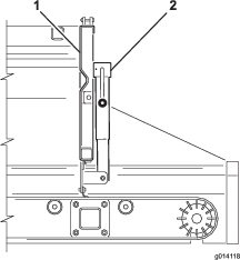
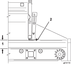
  2. Use the jack handle to open or close the adjustable section of the rear gate (Figure 39 and Figure 40). This restricts the flow of materials when using an option.

    Caution

    Use the adjustable section of the rear gate only when unloading material smaller than 1 inch (25 mm) in diameter, such as sand or gravel.

    Caution

    Open the rear gate completely if material will not flow through the adjustable section. Test each new material first.

    g014118
    g014119

Using the Twin Spinner

Installing the Twin Spinner

The machine comes equipped with a pair of quick attach mounting clamps. Use these clamps to mount the twin spinner to the machine.

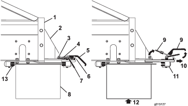
  1. Remove the safety latch clips from the clamp handles (Figure 41).

  2. Lift the safety latch, then lift the option attachment clamp handles, and release the lock rings from the lock pins (Figure 41).

  3. Slide the rear option attachment clamp assembly out of the quick attach slots (Figure 41).

  4. With assistance, insert the front edge of the twin spinner up and under the rear of the machine into the front clamps on the brackets (Figure 41).

  5. While supporting the twin spinner, slide the rear option attachment clamp assembly back into the slots in the brackets, and over the rear edge (Figure 41).

  6. Ensure that the twin spinner is centered between the brackets. Then re install the lock rings over the lock pins and push down on the clamp handles

    Note: If the clamp assembly is too loose and the twin spinner slides within the clamps, turn the lock rings into the clamps a few turns until the twin spinner is secure.

    Important: Do not over tighten the clamps. This may bend the edges of the twin spinner.

  7. Install the safety latch clips to the clamp handles (Figure 41).

    Caution

    Ensure that you reinstall the safety latch clips into the clamps. Otherwise, the clamps may open during operation.

    Warning

    The options are heavy. Use an assistant to help lift the twin spinner.

    g015127

Connecting the Hydraulic Hoses

Warning

Ensure that the tow vehicle is turned off before making the hydraulic connections, to prevent the cross conveyor/swivel from accidentally turning on.

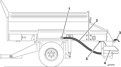
Connect the hydraulic hoses to the option control valve on the machine as follows (Figure 42):

  • Pull back (or push forward) on the outer sleeve of the female connector and insert the male connector.

  • Hold the male connector firmly in place and release the outer sleeve of the female connector.

  • Ensure that the connectors are pushed all the way in and are securely locked in place.

  • With the tow vehicle hydraulics operating, pull back on the option control lever on the SH models or start the option using the option start button on the handheld remote on the EH models, and ensure that the twin spinner is operating properly.

g014079

Setting the Desired Spread Pattern

You can set the spread pattern to the following settings:

  • A (Blue)—Ultra Light Pattern

  • B (Yellow)—Light to Heavy Spread Pattern

    g015028

    Note: The Twin Spinner is shipped from the factory in the B position.

    Review the blade position and adjust the blades, if necessary.

    Note: For this example we will select Yellow.

Setting the Drop Zone Position

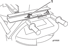
  1. Loosen the handle on each side of the twin spinner (Figure 44).

    g015025
  2. Slide the twin spinner, fore and aft, until the arrows match the desired color (yellow for this example).

  3. Tighten the handles.

Adjusting the Spinner Valve

SH models:

  1. Loosen the knob securing the spinner valve lever (Figure 45).

    g015024
  2. Rotate the spinner valve lever (Figure 45) to the desired color (yellow for this example).

EH models:

  1. Move the spinner valve lever to the Blue section (MAX SPEED) (Figure 45). Fully turned clockwise the lever should be horizontal.

  2. Use the spinner percent listed on the spread pattern decal or the wireless remote decal to determine the value that is put into the handheld remote.

    Note: For this example we will set the option percent to 50 percent matching the yellow color spread pattern previously selected.

Adjusting the Hopper Gate and Belt Speed

SH models:

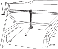
Rotate the crank to adjust the gate (Figure 46) until the arrow aligns with the center of the desired color (yellow for this example).

Note: The adjustment of the spread density is controlled through the main hopper gate opening or through the tow vehicle speed.

g015026

EH models:

  1. Rotate the crank to adjust the gate (Figure 46) until the arrow aligns with the center of the desired color (yellow for this example).

    Note: The adjustment of the spread density is controlled through the main hopper gate opening or through the tow vehicle speed.

  2. Using the handheld remote, set the floor belt speed percentage to match your desired speed pattern color.

    Note: For this example we will set the option percent to 80 percent matching the yellow color spread pattern previously selected.

Adjusting the Main Hopper Height

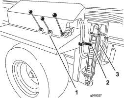
Using the hydraulic controls on the SH model or the handheld remote on the EH model, adjust the main hopper hydraulic cylinders until the arrow aligns with the GREEN section on the hydraulic cylinder decal (Figure 47).

g015027

Operating the Twin Spinner

  1. Turn off the tow vehicle

  2. On SH models, using the control levers, turn on the option and the conveyor belt (unload position).

  3. For both the SH and EH models adjust the settings, spread pattern, and flow rate.

    Note: You may have to experiment until you get the desired flow and spread depth. Other variables include ground speed and the type of material. Different materials vary in particle size, which can vary the spread pattern.

    Always test new materials by spreading them in an open area away from people.

  4. Start the tow vehicle and turn on the tow vehicle hydraulics.

  5. On the SH model turn on the on/off pendant switch to start spreading. On the EH model turn on the option then the conveyer belt with the handheld remote.

  6. On the SH model turn off the on/off pendant switch to stop spreading. The Twin Spinner will continue to operate. On the EH model turn off the conveyer belt and then the option.

  7. For EH models you can use the ALL START function in place of the OPTION START and BELT START functions as a single operation start feature. The option will start first, then followed by the belt.

  8. When the machine is empty, turn off the hydraulics before transporting the machine.

    Note: When driving over uneven terrain, raise the machine to the maximum safe traveling range. This provides more ground clearance for the Twin Spinner.

    Warning

    Watch for people and other objects while spreading. The Twin Spinner can throw material at high speeds up to 40 feet (12 m).

    Important: While traveling but not spreading, raise the machine to the maximum safe traveling distance, and turn off the Twin Spinner.

Fine Tuning the Twin Spinner

  1. Verify that all the settings are correct.

  2. If the spread pattern is not to the desired consistency, loosen the handles and slide the hopper in the desired direction to attain the desired spread pattern.

    decal119-6866

Setting Up the Cross Conveyor/Swivel

Installing the Cross Conveyor/Swivel

The cross conveyor spreads material to either side of the machine while the swivel kit allows the cross conveyor to swivel freely in a 270 degree arc, or to be locked into one of five fixed positions, 45 degrees apart.

Note: The machine comes equipped with a pair of quick attach mounting clamps. Use these clamps to mount the cross conveyor/swivel to the machine.

  1. Position the cross conveyor/swivel so the swivel kits two mounting brackets face toward the rear (away from the machine).

  2. Ensure that the cross conveyor/swivel is centered between the mounting brackets and that the motor extends out the same side as the control handles on the machine.

  3. Remove the safety latch clips from the clamp handles (Figure 49).

  4. Lift the safety latch, then lift the option attachment clamp handles, and release the lock rings from the lock pins (Figure 49).

  5. Slide the rear option attachment clamp assembly out of the quick-attach slots (Figure 49).

    g015127
  6. With assistance, insert the front edge of the cross conveyor/swivel up and under the rear of the machine into the front clamps on the brackets (Figure 49).

  7. While supporting the cross conveyor/swivel, slide the rear option attachment clamp assembly back into the slots in the brackets, and over the rear edge (Figure 49).

  8. Ensure that the cross conveyor/swivel is centered between the brackets. Then re-install the lock rings over the lock pins and push down on the clamp handles.

    Note: If the clamp assembly is too loose and the cross conveyor/swivel slides within the clamps, turn the lock rings into the clamps a few turns until the cross conveyor/swivel is secure.

    Important: Do not over-tighten the clamps. This may bend the edges of the option.

  9. Install the safety latch clips to the clamp handles (Figure 49).

    Caution

    Ensure that you reinstall the safety latch clips into the clamps. Otherwise, the clamps may open during operation.

    Warning

    The options are heavy. Use an assistant to help lift the cross conveyor/swivel.

Connecting the Hydraulic Hoses

Warning

Ensure that the tow vehicle is turned off before making the hydraulic connections, to prevent the cross conveyor/swivel from accidentally turning on.

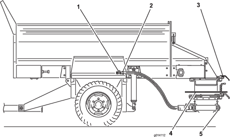
Connect the hydraulic hoses to the option control valve on the machine as follows (Figure 50):

  • Pull back (or push forward) on the outer sleeve of the female connector and insert the male connector.

  • Hold the male connector firmly in place and release the outer sleeve of the female connector.

  • Ensure that the connectors are pushed all the way in and are securely locked in place.

  • With the tow vehicle hydraulics operating, pull back on the option control lever on the SH models or start the option using the OPTION START button on the handheld remote on the EH models, and ensure that the cross conveyor/swivel is operating properly.

g014112

Operating the Cross Conveyor

Extending and Retracting the Cross Conveyor

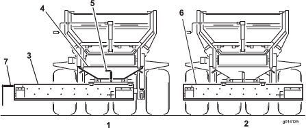
Always operate the cross conveyor (Figure 51) separately from the main conveyor belt.

Caution

Always return the cross conveyor to the center position when traveling, otherwise the cross conveyor can hit people or objects, and can also be damaged.

  1. Remove the safety pins from both option attachment clamps on the swivel kit.

  2. Loosen the option attachment clamp brackets

  3. Slide the conveyor to the center or side.

  4. Re-tighten the clamp brackets.

  5. Re-install the safety pins.

  6. On SH models adjust the speed of the cross conveyor with the hydraulic lever on the right. On EH models adjust the speed of the cross conveyer with the wireless remote.

    Note: Always lower the hopper before adjusting the cross conveyor. Otherwise, the cross conveyor will rest at an angle.

    g014125

Spreading Material from the Cross Conveyor

  1. Turn off the tow vehicle.

  2. On SH models using the control levers, turn on the option and the conveyor belt (unload position).

  3. Open the adjustable section of the rear gate to allow for the desired flow rate. You may have to experiment until you get the desired flow and spread depth. Other variables include ground speed and the type of material

  4. Turn on the tow vehicle hydraulics.

  5. On EH models operate the option and the conveyer belt with the wireless remote.

  6. On SH models turn off the tow vehicle hydraulics to stop material movement, or turn off the on/off pendant switch.

    Note: For SH models the on/off pendant switch stops the machine conveyor belt, not the cross conveyor.

  7. When finishing using the cross conveyor, always return it to the center position.

Operating the Swivel Kit

To direct the flow of material from the cross conveyor in any direction, pull up the spring-loaded locking pin on the swivel kit into the unlock or open position. This allows you to manually move the cross conveyor freely from side to side on the swivel bearing (Figure 51).

To keep the cross conveyor in a fixed position, release the spring-loaded locking pin into one of the five locking positions on the swivel kit.

Note: When traveling over uneven terrain, raise the machine to the maximum safe traveling range. This provides more ground clearance for the cross conveyor/swivel.

g015027

After Operation

After Operation Safety

  • Park the machine on a firm, level surface; engage the parking brake; shut off the engine; remove the key; and wait for all movement to stop before leaving the machine.

  • Avoid soft ground because the jack leg could sink and cause the machine to tip over.

  • Do not disconnect the machine from the tow vehicle on hills, or without engaging the jack and rear-jack leg.

  • When disconnecting the machine, always chock the wheels to prevent movement.

  • Keep all parts of the machine in good working condition and all hardware tightened.

  • Replace all worn or damaged decals.

Disconnecting the Machine from the Tow Vehicle

  1. Park the tow vehicle and the machine on dry, level ground.

  2. Set the parking brake on the tow vehicle, shut off the engine, and remove the key.

  3. Place blocks under the front and back of the wheels.

  4. Relieve the pressure from the hydraulic system.

  5. Disconnect the hydraulic hoses and the power harness (Figure 21 or Figure 22) from the tow vehicle. Coil and store them on the front of the machine.

  6. Unplug the power brake cable from the socket on the tow vehicle and store it on the machine (Figure 11).

  7. On SH models, disconnect and remove the control pendant for dry storage. On EH models, store the handheld remote in a dry safe place. Ensure that you have pressed the E-STOP button in.

  8. Turn the front jack and rear jack leg 90 degrees (clockwise) to the down position to support the machine.

  9. Lift the machine with the jack until the weight is off the tow vehicle’s draw bar. Pull out the hitch pin.

  10. Ensure that there is no further connection between the machine and the tow vehicle.

Maintenance

Note: Download a free copy of the schematic by visiting www.Toro.com and searching for your machine from the Manuals link on the home page.

Maintenance Safety

  • Before servicing or adjusting the machine, stop the machine, shut off the engine, engage the parking brake, remove the key, and wait for all moving parts to stop.

  • Perform only those maintenance instructions described in this manual. If major repairs are ever needed or assistance is desired, contact an authorized Toro distributor.

  • Before doing any maintenance work under the hopper, install the hydraulic cylinder supports.

  • Ensure that the machine is in safe operating condition by keeping nuts, bolts, and screws tight.

  • If possible, do not perform maintenance while the engine is running. Keep away from moving parts.

  • Do not check or adjust the chain tension when the tow vehicle engine is running.

  • Carefully release pressure from components with stored energy.

  • Support the machine with blocks or jack stands when working beneath it.

  • After maintaining or adjusting the machine, ensure that all guards are installed.

Premaintenance Procedures

Warning

Disconnect all power sources to the machine before doing maintenance work.

Warning

Install the hydraulic cylinder supports before doing any maintenance work under the hopper (Figure 53).
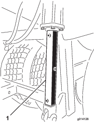
g014128

Lubrication

The machine has grease fittings that must be lubricated regularly with No. 2 General Purpose Lithium Base Grease. If machine is operated under normal conditions, lubricate all bearings and bushings after every 50 hours of operation. Bearings and bushings must be lubricated daily when operating conditions are extremely dusty and dirty. Dusty and dirty operating conditions could cause dirt to get into the bearings and bushings, resulting in accelerated wear. Lubricate grease fitting immediately after every washing, regardless of interval specified.

  1. Wipe grease fitting clean so foreign matter cannot be forced into the bearing or bushing.

  2. Pump grease into the bearing or bushing.

  3. Wipe up excess grease.

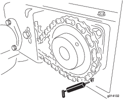
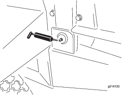
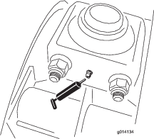
    The bearing and bushing lubrication points are as follows:
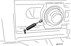
    g014131
    g014132
    g014133
    g014134

Safety Checks

At the start of each day, complete these safety checks before operating the machine. Report any safety problems to your supervisor. See the Safety Instructions in this manual for details.

Note: Photocopy these pages and use them as a regular safety checklist

Tires and Wheels

  • The recommended tire pressure is 172 kPa (25 psi) for 84 cm (33 inch) tires and 207 kPa (30 psi) for 81 cm (32 inch) tires, or as recommended by the tire manufacturer.

  • Check for excessive wear or visible damage.

  • Check that the wheel bolts are tight and none are missing.

Rear Gate

  • Check that the rear gate closes and latches securely.

  • Check that the adjustable section of the rear gate opens and closes without sticking.

Hitch, Jack, and Rear Jack Leg

  • Check that the hitch pin and jacks are not damaged, and the safety pins are in place. (Replace missing or damaged safety pins.)

  • Check that the hitch connections are not loose. (If so, install a spacer between the hitch connections.)

  • Safely stow all jacks in the up position before traveling.

Hydraulic System

  • Check the hydraulic system for oil leaks. If you find a leak, tighten the fitting, or replace or repair the damaged part.

  • Check the hydraulic hoses for wear or visible damage.

  • Check the hydraulic oil level. Fill up if necessary.

Conveyor Belt and Rollers

  • Once a week, check that the conveyor belt is tracking straight on the rollers and does not slip. Make adjustments if required.

  • Every four months, check that the idler rollers between the front and rear rollers are not bent or seized. Replace or repair if required.

Belt and Rear Gate Seals

Check all rubber seals for wear or damage. Replace or repair the seals if any leakage occurs.

Options

  • Check that the quick attach brackets are securely locked into place and that the safety clips are installed. Replace missing safety clips.

  • Check that the option is securely clamped and does not move or slide out. Adjust clamps if required.

  • Check the paddles on the Twin Spinner disks for wear. Replace them when they wear thin.

  • Check the Twin Spinner housing for signs of cracking or corrosion.

Safety Decals

Check that the safety decals are undamaged and legible, otherwise replace them.

Electric Brakes

  • Once a month, conduct a simple visual inspection of your brake shoes and linings.

  • Inspect and service your electric brakes once a year.

Hydraulic System

The machine is shipped from the factory filled with high quality hydraulic fluid. Check the level of hydraulic oil before the machine is first started and daily thereafter. The recommended replacement oil is as follows:

 Toro Premium Transmission/Hydraulic Tractor Fluid (Available in 5 gallon pails or 55 gallon drums. See parts catalog or Toro distributor for part numbers.)

Alternate fluids: If the Toro fluid is not available, other petroleum-based Universal Tractor Hydraulic Fluids (UTHF) may be used provided its specifications fall within the listed range for all the following material properties and it meets industry standards. We do not recommend the use of synthetic fluid. Consult with your lubricant distributor to identify a satisfactory product.

Note: Toro will not assume responsibility for damage caused by improper substitutions, so use only products from reputable manufacturers who will stand behind their recommendation.

 Material Properties:
  Viscosity, ASTM D445cSt @ 40°C 55 to 62
  Viscosity Index ASTM D2270140 to 152
   cSt @ 100°C 9.1 to 9.8
  Pour Point, ASTM D97-35°F to -46°F
 Industry Specifications:
  API GL-4, AGCO Powerfluid 821 XL, Ford New Holland FNHA-2-C-201.00, Kubota UDT, John Deere J20C, Vickers 35VQ25, and Volvo WB-101/BM

Changing Tires

Changing an Outside Tire

  1. Keep the machine attached to the tow vehicle, remove any options, and apply the emergency brake.

  2. Remove all material from the hopper.

  3. Block the tires on the opposite side of the flat tire.

  4. Loosen the six wheel bolts on the flat tire with a lug wrench, but do not remove them.

  5. Hoist or jack the machine until the tire is off the floor or ground. Ensure that the machine is stable.

  6. Remove the loose wheel bolts and remove the tire.

  7. Repair the damaged tire.

  8. Re install the tire onto the machine by reversing the above steps.

    Note: Ensure that the wheel is centered on the hub and all six wheel bolts are tight. Torque in a crossover pattern to 135 N-m (100 ft-lb).

Changing an Inside Tire

  1. Keep the machine attached to the tow vehicle, remove any options, and apply the emergency brake.

  2. Remove all material from the hopper.

  3. Block the tires on the opposite side of the flat tire.

  4. On the side with the tire to be changed, remove the 4 bolts holding the walking beam suspension's bearings to the chassis. (Loosen but do not remove the outside wheel nuts to give more clearance for bearing bolts).

  5. Hoist or jack the machine until the inside tire and walking beam axle assembly can be rolled out from underneath. Ensure that the machine is stable.

  6. Remove the tire.

  7. Repair the damaged tire.

  8. Re install the tire onto the machine by reversing the above steps.

    Note: Ensure that the wheel is centered on the hub and all six wheel bolts and the bearing bolts are tight to 135 N-m (100 ft-lb).

Tracking the Conveyor Belt

If the conveyor belt is not centered and tracks to one side, it needs to be adjusted (Figure 58). The best time to do this is between loads during operation.

  1. Go to the rear of the machine and determine which side of the belt is touching.

  2. Go to the front on the same side, loosen the locking nut, and tighten the adjuster nut by one quarter turn.

  3. Tighten both locking nuts before running the machine.

  4. Load the machine with material and run the load through until empty. Repeat multiple times.

  5. Stop the belt and go to the rear of the machine to observe the results.

    You may need to repeat the above steps several times until the belt begins to move and track properly.

    Note: The belt may move slightly depending on the type of load and its position. If the belt is not touching the side rails, you do not need to track the belt.

    Important: Do not adjust the belt’s rear drive roller. It is set to factory specifications. Contact your authorized Toro distributor if adjustment is required.
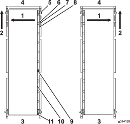
    g014129

Tensioning the Conveyor Belt

Check and adjust the belt tension frequently (Figure 58). All rubber conveyor belts will stretch, especially when they are new or have not been used for awhile.

  1. Park the machine on level ground with the rear gate and feed gate at least 6.25 mm (1/4 inch) off the floor (depending on the material).

  2. Fully load the machine with sand that you expect the machine to use.

  3. Remove the black front covers on either side of the machine.

  4. Using two wrenches, hold the end of the tensioner rod stationary, while loosening the locking nut closest to the end of the rod.

  5. Move the locking nut back 2–5 cm (1–2 inches).

    Warning

    Use extreme caution around moving parts with safety guards removed.

  6. Turn on the conveyor belt.

  7. If belt slips, tighten the tension bolts evenly (with machine off) half a turn and recheck. Continue until the belt moves without any slippage.

  8. Give both tensioning bolts another half turn. At this point you should have proper tension.

  9. To verify, look underneath at the chassis cross member. The middle of the belt should just clear the chassis cross member when the machine is in the down position. If the middle of the belt is touching the cross member, tighten both tensioning bolts another quarter of a turn.

    Important: Be patient. Do not over-tension the belt.

    Important: Do not use air tools on the belt tensioning bolts.

Changing the Conveyor Belt

Read these instructions before removing the belt. If the belt is completely destroyed, simply use a knife to cut the belt in an undamaged area. If you intend to make a warranty claim, the belt supplier must inspect the belt to evaluate the damage and make recommendations for replacement.

Removing the Belt

  1. Remove the black safety covers located on the four outer corners of the machine.

  2. Remove the guides for the inner rubber liner from the front and both sides of the hopper, with the metal rails attached.

  3. Remove the silicone sealer on the rear of the metal rails (but remember to re apply the silicone sealer when re installing them).

  4. At both front corners, use two wrenches to hold the end of the tensioner rod stationary.

  5. Loosen the nut closest to the end of the tensioning rod.

  6. Move the inside adjusting nut back until the tensioning rod clears the pillow block bearing.

    Note: The front idler roller is supported by two pillow block bearings sitting in an upper and lower guide (one set on each side of the machine).

  7. Support the front idler roller.

  8. Go to the right front corner and remove the locking collar that holds the pillow block bearing on the shaft. Do this by backing off the set screws and turning the locking collar counterclockwise. Using a hammer and punch, tap the locking collar counterclockwise until it releases from the shaft.

  9. Repeat this step for the left front corner.

  10. Remove the pillow block bearings by sliding the idler roller back so the pillow block bearings slide out of their guides.

  11. Remove the two safety brackets and slide the roller down through the open hole.

  12. Go to the rear of the machine and loosen the tensioning sprocket.

  13. Remove the chain from the drive sprocket.

  14. Loosen the set screws on the drive sprocket and remove the drive sprocket and key from the drive roller shaft.

  15. Support the rear drive roller.

    Important: Do not disturb the rear roller adjustment bracket assembly. It is designed to adjust the rear roller automatically if the belt is not tracking accurately

  16. Remove the four bolts in the flange bearings on both sides.

  17. Remove the locking collars next to the flange bearings on the shaft, and slide both bearings off the shaft.

  18. Remove the two option attachment brackets (Figure 59).
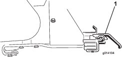
    g014104
  19. Lower the drive roller down through the slots.

  20. Remove the rear gate for a better view.

  21. Note the position of the cartridge inside the hopper, so that you can re install it in the same position and direction. It is bolted in six places along the side of the machine (three 4 bolt plates on each side).

  22. Secure the cartridge by using straps from a lifting device on each of the four corners.

  23. Remove the 24 bolts to release the cartridge (Figure 60).
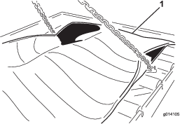
    g014105
  24. Remove the cartridge by lifting it out from the top of the machine. Place it on the ground (Figure 61).
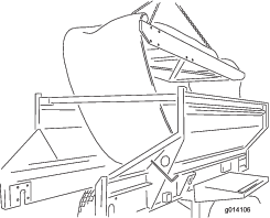
    g014106

Installing the Belt

To install a new belt, reverse the above instructions, but keep in mind the following important notes and instructions.

Important: The conveyor belt is designed to work primarily in one direction. Ensure that the painted arrow in the middle of the belt is pointing towards the rear of the machine (looking down from above).

Note: Before sliding the rear drive roller back up through the slot and into place, ensure that you have already installed the four bolts (from the inside facing out) for connecting the pillow block bearings. Otherwise, you will have to remove the drive roller to gain enough clearance to install these bolts.

When installing the rear drive roller, ensure that the shaft connecting to the motor is on the left side. It has a keyhole cut into it for securing the drive sprocket.

Before applying tension with the tensioner rods at the front of the machine, use your hands to manually center the belt at the front and rear.

Track and tension the belt by following the instructions in the Maintenance Section of the manual.

The front idler and rear drive rollers provide excellent traction for pulling the belt under load, so do not overtighten or stretch the belt.

Apply silicone sealer to the rear side of the metal rails and at the two front corners of the floor where the rails meet. The sealer deflects any material from getting past the rails.

Adjusting the Conveyor Drive Chain

If the conveyor drive chain is loose, it needs to be tightened (Figure 62).

  1. Turn off the tow vehicle and set the parking brake.

  2. Remove the rear conveyor drive guard.

  3. Loosen the bolt that goes through the tensioner sprocket.

  4. Tighten the positive locking screw using moderate force.

  5. Tighten the tensioner sprocket bolt.

  6. Check that the chain is sufficiently lubricated and the sprockets are secure to the shafts.

  7. Replace the rear conveyor drive guard.

    Caution

    Do not over tension the chain. Leave just enough tension to take up the extra slack.
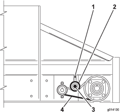
    g014130

Maintaining the Electric Brakes

Inspecting the Electric Brakes

Once a month, conduct a simple visual inspection of your brake shoes and linings.

Inspect and service your electric brakes once a year.

Adjusting the Electric Brakes

Adjust the electric brakes after the first three months of operation, or sooner depending on use or performance.

  1. Jack up the machine securely.

  2. Ensure that the wheel and drum rotate freely.

  3. Remove the adjusting hole cover from the slot on the bottom of the brake backing plate.

  4. With a screwdriver, rotate the star wheel of the adjuster assembly to expand the brake shoes (Figure 63).
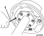
    g014826
  5. Adjust the brake shoes out until the pressure of the linings against the drum makes the wheel difficult to turn.

  6. Rotate the star wheel in the opposite direction until the wheel turns freely with a slight drag on the lining.

  7. Replace the adjusting hole cover.

  8. Repeat the above procedure on each brake.

Inspecting the Brake Shoes and Linings

Once a month, conduct a simple visual inspection of your brake shoes and linings.

When a brake shoe becomes worn, replace both shoes on each brake, and both brakes on the same axle. This ensures that the brakes remain balanced.

Replace the brake linings when they are

  • worn to 1/16 inch (1.6 mm) or less remaining thickness

  • contaminated with grease or oil

  • abnormally scored or gouged

    Note: Hairline heat cracks are normal in the brake linings and should not cause concern.

Yearly Brake Cleaning and Inspection

Inspect and service your electric brakes once a year or more often with heavy use or declining performance

  • Change magnets and shoes when they become worn or scored.

  • Clean the backing plate, magnet arm, magnet, and brake shoes with an automotive brake cleaner.

  • Ensure that all parts removed are replaced in the same brake and drum assembly that they were removed from.

  • Inspect the magnet arm for any loose or worn parts.

  • Check the shoe return springs, the hold down springs, and the adjuster springs for stretch or deformation and replace them if required.

    Caution

    Brake dust can be hazardous to your health if inhaled, take precautions when servicing brakes:

    • Do not create or breathe dust.

    • Do not machine, file, or grind the brake linings.

    • Do not use compressed air or dry brushing for cleaning.

Brake Lubrication

Before reassembling the electric brakes, apply a light film of anti seize compound, or grease such as “Lubriplate,” on the:

  • brake anchor pin

  • actuating arm bushing and pin

  • areas on the backing plate that are in contact with the brake shoes and magnet lever arm

  • actuating block on the actuating arm

Important: Do not allow grease to contact the brake linings, drums, or magnets.

Inspecting the Magnets

The brakes’ electromagnets are designed to provide the proper input force and friction.

Inspect the magnets regularly, and replace if they become unevenly worn. Use a tool with a straight edge to check wear.

Even if the wear is normal, you should replace the magnets if any part of the magnet coil is visible through the friction material on the magnet face. Replace the magnets in pairs (both sides of an axle).

When replacing the magnets, also resurface the drum armature surface.
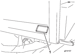
Storage

Before storing the machine for the season:

  1. Thoroughly clean the machine. Remove parts if necessary.

  2. Remove the handheld remote. Also, remove the batteries from the Remote.

  3. Check all fasteners and tighten, if necessary.

  4. Grease all fittings and pivot points. Wipe off any excess lubricant.

  5. Lightly sand any painted areas that are scratched, chipped, or rusted, and apply touch up paint.

  6. Store the machine indoors, if possible.

Troubleshooting

Checking Fault Codes (EH Models Only)

If the Diagnostic LED indicates that there is a system fault (refer to Diagnostic LED Function (EH Models)), check the fault codes to determine what is wrong with the machine.

Entering Diagnostic Mode and Checking the Codes

  1. Push the E-STOP button down to turn off the power.

  2. Pull the tethered cap off of the two diagnostic, shunt connectors (Figure 64, A).

  3. Connect the diagnostic, shunt connectors together (Figure 64, B).

    g028876
  4. Pull the E-STOP up to turn on the power.

  5. Count the number of flashes to determine the fault code, then consult the following table:

    Note: If there are multiple faults, both faults will flash, then a long pause, then the flash sequences will repeat.

    CodeLED Flash PatternBehaviorDetails
    Machine Specific Faults
    11Blink once, pause, blink once, long pause, then repeatLost communication with BASE.Connector not plugged in; locate the loose or disconnected harness connector and connect it.
    Something wrong in the wiring; contact your Toro Distributor.
    BASE is bad; contact your Toro Distributor.
    12Blink once, pause, blink twice, long pause, then repeatVersion incompatibility of the BASE and/or HHWrong software (install the correct software from TORODIAG); contact your Toro Distributor.
    13Blink once, pause, blink 3 times, long pause, then repeatWrong HH—not implemented on RevAWrong product association (i.e. trying to update software on a MH–400 with a ProPass handheld)

Reseting the Fault Code

After solving the problem, reset the fault codes by disconnecting and reconnecting diagnostic connectors. The diagnostic light will flash continuously at 1 Hz (1 flash per second).

Exiting Diagnostic Mode

  1. Push the E-STOP button down to turn off the power; refer to E-Stop button.

  2. Disconnect the diagnostic, shunt connectors.

  3. Push the tethered cap onto the two diagnostic, shunt connectors.

  4. Pull the E-STOP up to turn on the power.

Handheld Remote Messages (EH Models Only)

Displayed MessageDescription
ASSOC PENDINGAssociation yet to be made.
ASSOC ACTIVEAssociation attempt in progress.
POWER UP BASEPower up the Base Unit.
ASSOC PASSAssociation attempt was successful.
ASSOC EXITExiting Association mode
ASSOC FAILAssociation attempt failed.
PRESS STOREPress the STORE button.
ALL STOREStore all current set values in current working memory.
OPTION STOREStore the current Option settings in current working memory.
BELT STOREStore the current Floor settings in current working memory.
PRESET 1 STOREStore the current Preset 1 setting in current working memory.
PRESET 2 STOREStore the current Preset 2 setting in current working memory.
PRESET 3 STOREStore the current Preset 3 setting in current working memory.
WAITING FOR BASERemote is waiting for a Base Unit response.
HOPPER UPRemote is sending Hopper Raise command.
HOPPER DOWNRemote is sending Hopper Lower command.
PROPASS REV XXProduct to which the system is set to control.
MH400 REV XXProduct to which the system is set to control.
BAT XX%Battery X.X VRemaining battery life in percentage.Remaining battery life in voltage.
CHANNEL XChannel in GHz currently being used by the system.
HH ID XXXXXXIdentity of the Handheld Remote
BASE ID XXXXXXIdentity of the Base Unit
FLR XX% OPT XX%The current Floor speed in percent. The current Option speed in percent.
FLRS XX% OPTS XX%Display of the stored regular Floor speed and Option speed with 0% command to the output allowing the operator to decide to use the current setting or change it.
FLR OFFOPT OFFDisplays the status of the floor and option when they are off.
SERVICE ACTIVEThe service tool is active.
SERVICE NO APPService has no valid application to run.