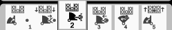
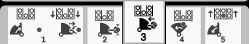
| Maintenance Service Interval | Maintenance Procedure |
|---|---|
| Every 400 hours |
|
Software Versions: A.5, A.6, and Rev B
Introduction
Read this information carefully to learn how to operate and maintain your product properly and to avoid injury and product damage. You are responsible for operating the product properly and safely. Read your Operator’s Manual for more information.
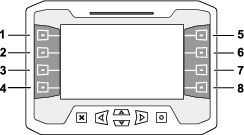
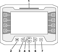
Product Overview
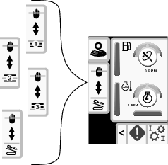
Display Screen Buttons
Exit-Side Lockout Disabled Startup Screen
Note: Software version A.5 and above.
This exit side lockout disabled warning will appear if you disabled the exit side lockout system.

See Exit Side Lockout Settings to enable the exit side lockout system
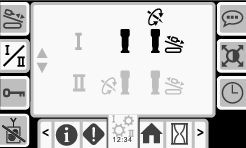
Home Screens
Main Information Screen
This is the first screen that appears after the initial splash screen. To navigate between screens, use the left and right arrows.
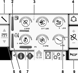
The pipe functions icon (Figure 4) will turn green when Smart Touch is turned on; refer to SmartTouch™ Home Screen.
| Exit side lockout status indicator: | |
|---|---|
| Disabled (black) | Enabled (green) |
 |  |
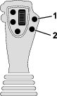
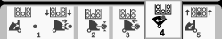
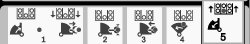
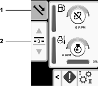
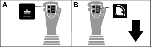
Push button 1 to switch between the pipe functions: pull pipe, push pipe, neutral, or manual pipe loading.
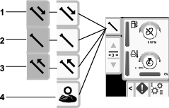
Push buttons 2 and 3 to switch choose a row.
In manual pipe loading mode, use buttons 2 and 3 to choose a row or to load the pipe to the drill string; refer to Manual Pipe Loading.
Push button 5 to switch between thrust force, drill speed (rpm), and rotary torque.
Use buttons 6 and 7 to set limits for the drill speed (rpm), rotary torque, and thrust force.
Setting the Rotary Speed
Use the OK (O) button on the display (Figure 2) to set the rotary speed.
Push the button to choose between high speed / low torque or low speed / high torque.
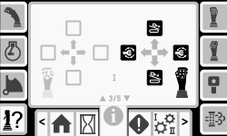
Cruise Mode and Screen
Software version Rev B and up.
Cruise mode is identified by this icon: 
Cruise mode provides hands-free operation for rotary and thrust, set by the operator.
Note: Use Cruise mode for pull back only. Using cruise mode in thrust could cause damage.
You can only use cruise mode with clockwise functions.
Accessing the Cruise Screen
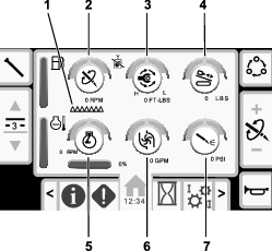
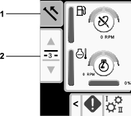
Push the cruise button on the joystick (Figure 10) or push button 4 on the home screen to access the cruise screen.
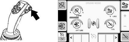
Push button 4 to switch between cruise and carve modes.
Activating Cruise
-
If necessary, set the machine limits; refer to the Main Information Screen .
-
Hold the joystick(s) in the active position for the amount of thrust and rotation speed you want and push the cruise button on the right joystick (Figure 10), then release the joysticks.
Once set, use the cruise screen to adjust the settings (Figure 10).
-
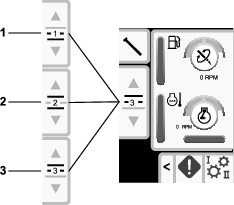
Push buttons 1, 3, 5, or 8 to select the setting to adjust.
Note: The icon turns green and a green circle highlights the option you select (Figure 11).
-
Push button 6 or 7 to increase or decrease the value of the selected setting.
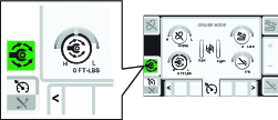
The following table describes the function values affected when another function is given priority.
The priority is the function with the highest value, not the value selected in the screen.
All values are dependent on the available engine horse power.
| Button | Priority | Icon | Description |
|---|---|---|---|
| 1 | Pipe rotation speed (Rotary RPM) |  | The set rotary RPM is maintained unless the set rotary torque is exceeded, then the rotary rpm is reduced. |
| 3 | Rotary Torque |  | The set rotary torque value is maintained unless the maximum set rotary RPM is exceeded, then the toque value is reduced. |
| 5 | Thrust force (Carriage Thrust) |  | The set carriage thrust is maintained unless the carriage rate (speed) is exceeded, then the thrust force is reduced. |
| 8 | Thrust rate (Carriage Rate/Speed) |  | The set carriage rate (speed) is maintained unless the maximum set carriage thrust is exceeded, then the speed is reduced. |
Push the X button to return to the Main Information Screen .
Deactivating Cruise
Push the cruise button to deactivate the cruise mode or push the joystick as follows:
-
Mode I: the right joystick in any direction
-
Mode II: the right or left joystick in forward or reverse.
Note: The settings reset when the key is turned off or when you switch to carve mode.
Resuming Cruise
Push the cruise button on the joystick to resume the functions with the same settings.
Note: The settings reset when the key is turned off or when you switch to carve mode.
Carve Mode and Screen
Carve mode is identified by this icon: 
Carve mode can only be set in thrust, not pullback.
Accessing the Carve Screen
Push the carve button on the joystick (Figure 12) or push button 4 on the home screen to access the carve screen.
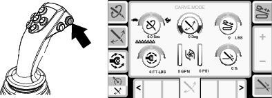
Push button 4 to switch between cruise and carve modes.
Activating Carve
-
Position the drill bit in the direction (clock position) that you need to steer/carve.
-
Return the joysticks to the neutral position.
-
Access the carve screen using the display.
-
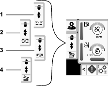
Push button 2 to select the sweep angle. Use buttons 6 and 7 to adjust the level.
-
Set the rotation speed, rotary torque, and thrust force using the carve screen on the display.
-
Push the carve button on the joystick (Figure 12).
Note: The drill string should start to rotate back and forth.
-
Push button 8 to access the thrust setting.
Note: The icon turns green and a green circle highlights the option you select (Figure 13).
-
Push button 6 to slowly increase the thrust rate to the desired setting.
-
Push button 6 or 7 to increase or decrease the value of the selected setting.
The following table describes the function values affected when another function is given priority.
The priority is the function with the highest value, not the value selected in the screen.
All values are dependent on the available engine horse power.
| Button | Priority | Icon | Description |
|---|---|---|---|
| 1 | Pipe rotation speed (Rotary RPM) | | The set rotary RPM is maintained unless the set rotary torque is exceeded, then the rotary rpm is reduced. |
| 2 | Sweep angle | | When not drilling: change the arc angle degree. The arc angle will increase or decrease by 18°. |
| When actively drilling: change the center of the pipe rotation. Button 6 is clockwise. Button 7 is counter clockwise. The pipe adjusts by 18° clockwise or counterclockwise for each button press. | |||
| 3 | Rotary torque | | The set rotary torque value is maintained unless the maximum set rotary RPM is exceeded, then the toque value is reduced. |
| 5 | Thrust force (Carriage thrust) | | The set carriage thrust is maintained unless the carriage rate (speed) is exceeded, then the thrust force is reduced. |
| 8 | Thrust rate (Carriage Rate/Speed) | | The set carriage rate (speed) is maintained unless the maximum set carriage thrust is exceeded, then the speed is reduced. |
Push the X button to return to the Main Information Screen .
Deactivating Carve
Push the carve button to deactivate the carve mode or push the joystick as follows:
-
Mode I: the right joystick in any direction
-
Mode II: the right or left joystick in forward or reverse.
Note: The settings reset when the key is turned off or when you switch to cruise mode.
Resuming Carve
Push the carve button on the joystick to resume the functions with the same settings.
Note: The settings reset when the key is turned off or when you switch to cruise mode.
SmartTouch
SmartTouch mode allows the operator to load and unload pipes from the pipe box with less joystick operation to reduce operator fatigue.
Use the Carriage Settings Screen to turn SmartTouch mode on and off.
Note: The Push/Pull Icon has a green background when SmartTouch mode is on and a ribbon appears at the bottom of the screen showing a sequence of the steps.
Important: Never switch between Push/Pull modes during the chosen operation. Use neutral (manual) mode to switch between Push/Pull; refer to Carriage Settings Screen to turn SmartTouch mode off.
Pulling Pipe in SmartTouch Mode
Start the SmartTouch mode with the cam assembly in the park position.
-
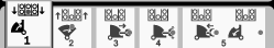
Push button 1 to select the pull pipe option (Figure 15).
-
Push buttons 2 and 3 to select the row where you want to place the pipe (Figure 15).
-
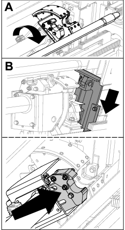
Hold the lower right button on the left joystick (Figure 14) until the display moves to box 2 (Figure 16) and the elevator lowers, the cam assembly rotates toward the operator station, and the arms fully extend (Figure 17).
-
Release the button to proceed to the next step in the sequence (Figure 18).
-
Break the pipe connection; refer to Removing Drill Pipes in the Operator’s Manual.
-
Hold the lower left button on the left joystick to grip the pipe (Figure 19 and Figure 20) and release the button.
-
Hold the lower right button on the left joystick (Figure 14) until the arms fully retract (Figure 22).
-
Release the button to proceed to the next step in the sequence (Figure 23).
-
Hold the lower right button on the left joystick (Figure 14) until the cam assembly rotates to the selected row under the pipe box (Figure 24).
-
Release the button to proceed to the next step in the sequence (Figure 25).
-
Hold the lower right button on the left joystick (Figure 14) until the display moves to box 1 and the elevator puts the pipe back in the pipe box and the cam rotates to the home position (Figure 26).
-
Release the button to start the pull-pipe process again.
Pushing Pipe in SmartTouch Mode
Start the SmartTouch mode with the cam assembly in the park position.
-
Push button 1 to select push pipe (Figure 28).
-
Push buttons 2 and 3 to select the row where you want to get the pipe (Figure 28).
-
Hold the lower right button on the left joystick (Figure 27) until the cam assembly rotates to the selected row and the pipe lowers into the opening (Figure 30).
-
Release the button to proceed to the next step in the sequence (Figure 31).
-
Hold the lower right button on the left joystick (Figure 27) until the display moves to box 3 (Figure 31) and the cam assembly fully rotates forward to the rack and the elevators lift the remaining pipe into the pipe box (Figure 32).
-
Release the button to proceed to the next step in the sequence (Figure 33).
-
Hold the lower right button on the left joystick (Figure 27) until the arms extend (Figure 34).
-
Release the button to proceed to the next step in the sequence (Figure 35).
-
Make the pipe connection; refer to Adding Drill Pipes in the Operator’s Manual.
-
Hold the lower left button on the left joystick (Figure 36) to release the pipe (Figure 37) and release the button.
-
Hold the lower right button on the left joystick (Figure 27) until the arms retract and the cam assembly returns to the home position (row 3) (Figure 39).
-
Release the button to start the push-pipe process again. The cam assembly goes to the row picked in step 2 of Pushing Pipe in SmartTouch Mode.
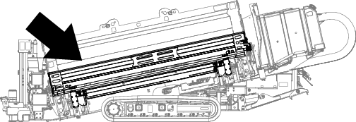
Manual Pipe Loading
Manual pipe loading mode allows the operators to load and unload pipes from the cam assembly when it is rotated outside the pipe box.
Note: Use 2 people to load the pipes into the cam assembly.
-
Set the machine to manual pipe loading mode; refer to Carriage Settings Screen..
-
Use buttons 2 and 3 to choose where you want the pipe to be placed; a row or the drill string (Figure 41).
-
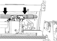
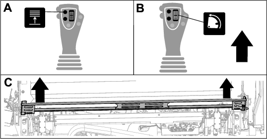
Raise the elevator (Figure 42).
-
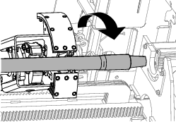
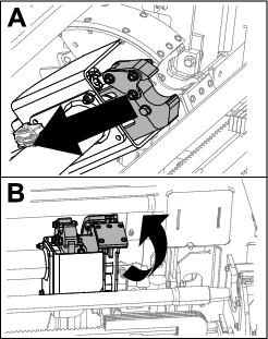
Push the cam rotate dial UP to rotate the cam assembly outside of the pipe box (Figure 42).
-
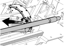
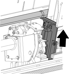
Raise the pipe loading guard (Figure 42).
-
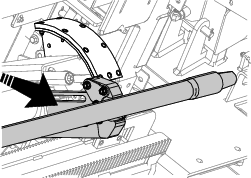
Use 2 people to load a pipe into the cam assembly (Figure 43).
-
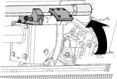
Lower the pipe loading guard (Figure 43).
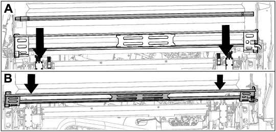
-
Lower the elevator (Figure 44).
-
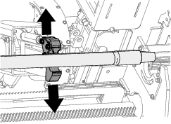
Push the cam rotate dial DOWN to rotate the cam assembly to the location picked in step 2 (Figure 44).
-
Loading to the drill string only: Refer to Adding Drill Pipes in the Operator’s Manual.
-
Repeat steps 3 to 9 to continue loading pipes to the pipe box.
Hours Screen Options
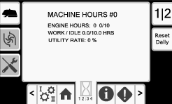
Machine Hours Screen
To access this screen push button 1 on the Hours screen.
This screen shows the operating hours of the machine. Machine 1 cannot be changed. Machine 2 can be reset.
Button 5 switches between machine 1 and machine 2.
Button 6 resets the daily machine hours.
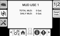
Drilling Fluid (Mud) Use Screen
To access this screen push button 2 on the Hours screen.
This screen shows the drilling fluid (mud) use of the machine. Total drilling fluid (mud) cannot be changed. Daily drilling fluid (mud) can be reset.
Button 5 switches between mud use 1 and mud use 2.
Button 6 resets the daily mud use.
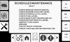
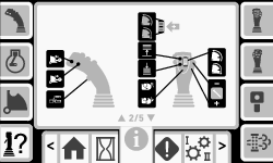
Maintenance Schedule Screens
To access this screen, push button 3 on the Hours screen.
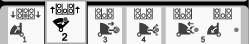
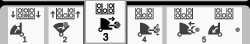
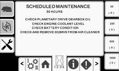
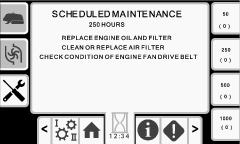
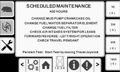
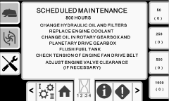
These screens provide the user with the daily maintenance schedules and the 50-hour, 250-hour, 400-hour, and 800-hour increments.
To reset the maintenance interval, refer to Maintenance PIN Screen.
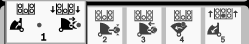
Push the following buttons to view the following maintenance schedules:
-
Button 3—Daily maintenance schedule (Figure 47)
-
Button 5—50-hour maintenance schedule (Figure 48)
-
Button 6—250-hour maintenance schedule (Figure 49)
-
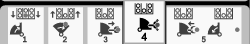
Button 7—400-hour maintenance schedule (Figure 50)
-
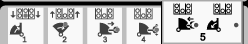
Button 8—800-hour maintenance schedule (Figure 51)
Settings Screen Options
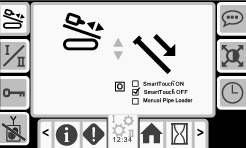
Carriage Settings Screen
Push button 1 on the Settings screen.
Use this screen to change the carriage settings. Push the OK button to switch between SmartTouch and the manual pipe loader option.
Use the up and down arrows to choose the push, pull, or neutral setting.
Push Pipe: refer to Starting the First Pipe and Adding Drill Pipes in the Drilling the Bore section in your Operator’s Manual for full instructions.
Pull Pipe: refer to Removing Drill Pipes in the Drilling the Bore section in your Operator’s Manual for full instructions.
Manual Pipe Loader: refer to Manual Pipe Loading.
Control Mode Screen
Push button 2 on the Settings screen.
Use this screen to select between the 2 joystick control options. Push the up and down buttons to switch between Mode I and Mode II.
-
Mode I—The right joystick controls the thrust and the rotation functions. Refer to Figure 70 on the Joystick Help Screen for more information.
-
Mode II—The right joystick controls the thrust functions. The left joystick controls the rotation functions. Refer to Figure 71 on the Joystick Help Screen for more information.
Maintenance Options Screen
Maintenance PIN Screen
Push button 3 on the Settings screen.
Push the OK button to access the PIN screen (Figure 55).
The Maintenance pin number is 12356.
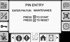
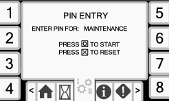
Resetting the Maintenance Intervals
-
Enter the maintenance PIN and await confirmation of correct PIN message.
-
Push the OK button to start the reset process.
-
Navigate to the Maintenance Schedule Screens.
-
Select the interval that you want to reset.
-
Push the interval number 2 more times to reset the interval.
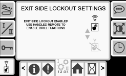
Exit Side Lockout Settings
Note: Software version A.5 and up
If your exit-side-lockout handheld remote loses its signal, runs out of batter power, or gets damaged, you can disable the system in order to continue working.
Push button 4 on the Settings screen to access the screen to enable/disable the exit side lockout system.
Use the up and down arrows to change the setting.
If you disable the exit side lockout, prior to working on the drill string, turn off the machine, remove and take the ignition key to the drill string operator/location. Once the drill string work is complete, you may start the machine and continue drilling.
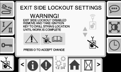
Warning message: Exit side lockout disabled. Remove and take ignition key to drill string location until work is complete.
Language and Units Options Screen
Push button 5 on the Settings screen to access the screen to switch between English and metric units. Use the up and down arrow keys to change the language and unit options.

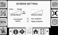
Screen Settings Screen
Push button 6 on the Settings screen to cycle through the different adjustments. Use the up and down arrows to adjust the parameters.
The Main Drilling Screen zooms into the drilling functions. These settings adjust the delay on how long it takes to zoom.
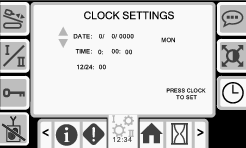
Clock Settings Screen
Push button 7 on the Settings screen to set the clock settings options.
Once you are on this screen, push button 7 to rotate between date, time, and 12/24.
Use the up and down arrows to adjust the parameters.
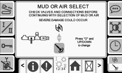
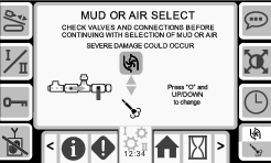
Mud or Air-Hammer Screens
Push button 8 on the Settings screen to access this screen. Hold the OK (O) button and use the up and down arrows to switch been mud and air hammer modes.
Important: Ensure that you set up the valves per your selection. Refer to the Air Hammer Installation Instructions.
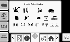
Information (I/O) Screens
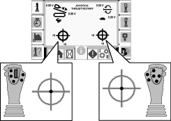
Joystick I/O and Calibration Screen
Joystick I/O Screen
Push button 1 on the I/O screen to access the Joystick I/O screen.
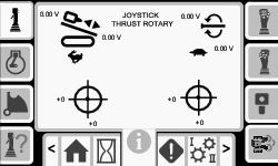
-
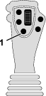
The rotary voltage ranges from 0.0 to 8.5 V and be present for either make (upper icon) or break (lower icon) as the selected rotary joystick is moved.
-
The carriage indicates a range from 0.0 to 10.0 volts in the joystick selected direction for thrust or pullback.
-
The lower left icon indicates if the left joystick is calibrated properly.
-
The lower right icon indicates if the right joystick is calibrated properly.
Calibrating the Joysticks
Use this screen to check the calibration of the joysticks. Refer to Calibrating the Travel Pendant to calibrate the travel pendant.
The red dot is in the center of the targets shows the movement of the left and right joysticks. If the red dot does not reach ±10,000, see your Authorized Service Dealer to service or replace your joystick.
Engine I/O Screen
To access this screen push button 2 on the I/O screen. This screen displays engine information.
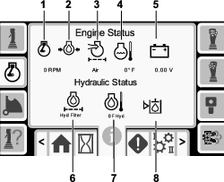
Engine speed (rpm): displays, in steps of 100, the engine speed (rpm).
Engine oil pressure: displays the engine oil icon .
Air filter: the air filter icon is green unless the filter is plugged then the indicator is red.
Engine temperature: displays the engine coolant temperature. The temperature drops to 40°F when the engine is off.
Battery voltage: displays the battery voltage. If the engine is off, the voltage is measured by the Toro controller.
Hydraulic-fluid filter: the hydraulic fluid filter icon is green unless the filter is plugged then the indicator is red.
Hydraulic-fluid temperature: displays the hydraulic fluid temperature.
Hydraulic-fluid level is low: the icon is red when the hydraulic fluid level is low
Cam Arm I/O and Calibration Screen
To access this screen push button 3 on the I/O screen.
Use this screen to calibrate the cam assembly.
-
Push button 3 to toggle the calibration on and off.
-
Push the up and down buttons on the monitor to select the load position and the pipe-row position.
-
Push the OK button 2 times on the desired position to save the calibration.
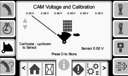
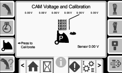
The voltage on the bottom indicates the cam raw sensor voltage. The voltages range from 1.0 to 4.0 V. Any voltage higher or lower indicates either sensor failure or incorrect calibration.
The other voltages are the calibrated voltages.
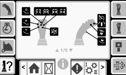
Joystick Help Screen
To access these screens push button 4 on the I/O screen.
These screens show the function of each joystick button.
Push the up and down arrows to scroll through the screens.
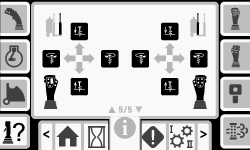
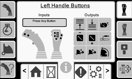
Left Joystick I/O Screen
To access this screen push button 5 on the I/O screen.
Push the buttons on the joysticks and ensure that the corresponding icon illuminates.
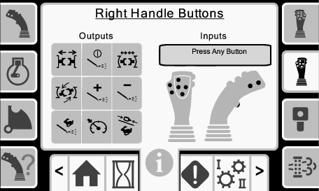
Right Joystick I/O Screen
To access this screen push button 6 on the I/O screen.
Push the buttons on the joysticks and ensure that the corresponding icon illuminates.
Travel Pendant I/O and Calibration Screen
Travel Pendant I/O Screen
To access this screen push button 7 on the I/O screen.
The travel pendant screen shows the voltage and position of the joystick located on the pendant.
Note: The message, Pendant Out Of Range, will appear if the pendant is out of range and cannot be calibrated. Bring the pendant closer to the machine to calibrate it.
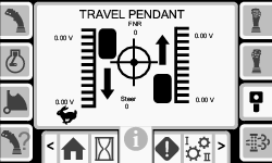
Calibrating the Travel Pendant
The red dot is in the center of the target and the FNR (forward, neutral, reverse) and Steer voltage shows 2.5 V prior to allowing the drill to move. If the red dot travels outside of the outermost black ring, service or replace the pendant.
The indicators to the right and left of the circle show the direction of the track travel. The voltages show a range from 0 to 10.0 V.
Engine DPF I/O Screen
To access this screen push button 8 on the I/O screen.
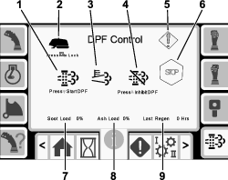
Manual regeneration (regen): Push the down arrow to start a regeneration cycle.
Regeneration interlock: Push the OK button to lock the machine during a manual regeneration.
High exhaust temperature: This icon displays when the exhaust temperature high.
Inhibit regeneration: Push the up arrow to postpone a regeneration cycle.
Warning symbol: This icon displays when a regeneration is due or there is an issue with the DPF.
Engine stop warning: This icon displays when a regeneration is required. The machine does not function until the process is completed.
Soot load: This is the soot load percentage. Perform a regeneration cycle when the soot load is at 50% or above.
Ash load: This is the ash load percentage. Perform a regeneration cycle when the ash load is at 10% or above.
Last regeneration: This is the number of hours since the last regeneration cycle.
Troubleshooting
Errors and Machine Information Screens
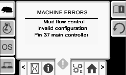
Drill Errors Screens
To access this screen push button 1 on the Errors and Machine Information screen.
This screen displays any drill errors.
Push buttons 5 to page through the errors.
Push button 6 to reset the error messages.
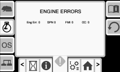
Engine Errors Screen
To access this screen push button 2 on the Errors and Machine Information screen.
This screen displays any engine errors.
Push buttons 5 to page through the errors.
Push button 6 to reset the error messages.
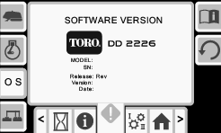
Software Information Screen
To access this screen push button 3 on the Errors and Machine Information screen.
This screen displays the machine and software information including the model, serial number, and software version.
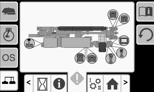
Machine CAN Information Screen
Push button 4 to access this screen.
If any of these icons are red, refer to your Service Manual.
Function I/O Screen
To access this screen, push button 8 from the Errors and Machine Information Screens.
| Controller | Icon | Color | Description |
| Seat Switch |  | Black | The operator seat is occupied. |
 | Green | The operator seat is unoccupied. | |
| Pedestrian Gate |  | Black | The gate is in the correct position for drilling. |
 | Black | The gate is not in the correct position for drilling. | |
| Exit Side Lockout |  | Black | The exit side lockout is not in operation. |
 | Green | The exit side lockout is in operation. | |
| Machine |  | Green | The machine is active. |
| Carriage |  | Green | The carriage is in operation. |
| Cam Assembly |  | Black | The cam assembly is in the neutral position. |
 | Green | The cam assembly is rotating forward. | |
 | Green | The cam assembly is rotating backward. | |
| Cam Arm |  | Black | The cam arm is not in operation. |
 | Black and Green | The cam arm is retracting. | |
 | Black | The cam arm extend function is not in operation. | |
 | Black and Green | The cam arm is extending. | |
| Pipe Gripper |  | Black | The pipe gripper is not in operation. |
 | Green | The pipe gripper is closing. | |
 | Green | The pipe gripper is opening. | |
| Elevator |  | Black | The elevator down function is not in operation. |
 | Green | The elevator is lowering. | |
 | Black | The elevator up function is not in operation. | |
 | Green | The elevator is raising. | |
| Grease |  | Black | The grease is not in operation. |
 | Green | The grease is activated. | |
| Vice/Stationary Wrench |  | Black | The vice/stationary wrench is not in operation. |
 | Green | The vice/stationary wrench is opening. | |
 | Green | The vice/stationary wrench is closing. | |
| Wrench |  | Black | The wrench is not in operation. |
 | Green | The wrench is closing. | |
 | Green | The wrench is opening. | |
 | Black | The wrench make/break function is not in operation. | |
 | Green | The wrench is rotating counter clockwise. | |
 | Green | The wrench is rotating clockwise. | |
| Spray Gun |  | Black | The spray gun is not in operation. |
 | Green | The spray gun is activated. | |
| Stake |  | Black | The stake (left/right) rotation function is not in operation. |
 | Green | The stake (left/right) is rotating clockwise. | |
 | Green | The stake (left/right) is rotating counter clockwise. | |
 | Black | The stake (left/right) raise or lower function is not in operation. | |
 | Green | The stake (left/right) is being raised. | |
 | Green | The stake (left/right) is being lowered. |
Warning Icons
| Warning | Icon | Description | Resolution |
|---|---|---|---|
| Carriage Crash |  |
| To clear this warning, do the following:
|
| Pipe Loading Guard |  | The pipe loading guard is not in the lowered position. | Lower the pipe loading guard. |
| Cam Voltage |  | The cam voltage is above or below the minimum or maximum values. | Check the Cam Arm I/O and Calibration Screen and calibrate the cam. |
| Travel Pendant |  |
|
|
| Carriage |  | The sensor on the drill carriage has an error. |
|
| Engine Air Filter |  | The air filter is restricted. | Refer to the Operator’s Manual to service the air filter. |
| Cold Hydraulic Oil |  | The hydraulic oil is colder than 4°C (40° F). | No action required. The engine rpm is limited to no more than 1100 rpm. |
| Cool Hydraulic Oil |  | The hydraulic oil is colder than 15°C (60°F). | No action required. The engine rpm is limited to no more than 1800 rpm. |
| Hot Hydraulic Oil (This icon is replaced in version A.6 and above. See section below.) |  | The hydraulic oil is hotter than 93°C (200°F). | No action required. |
| Low Hydraulic Oil |  | The hydraulic oil is low and needs to be checked and filled. | Refer to the Operator’s Manual to service the hydraulic oil. |
| Software version A.5 | |||
| Exit Side Lockout Disabled | |
The exit side lockout is disabled | To clear this warning, do the following:
|
| Software version A.6 | |||
| Hot Oil Warning |  | The oil temperature is between 195°F (91°C) and 210°F (99°C). Functionality will be limited until the temperature drops below these levels. | Push the X button to cancel the alarm. |
| Hot Oil Caution |  | The oil temperature is over 210°F (99°C). Functionality will be limited until the temperature drops below these levels. | Push the X button to cancel the alarm. |