


Maintenance
Recommended Maintenance Schedule(s)
| Maintenance Service Interval | Maintenance Procedure |
|---|---|
| After the first 5 operating hours |
|
| Before each use or daily |
|
| Every 25 hours |
|
| Before storage |
|
Caution
If you leave the key in the traction unit ignition switch while the tiller is attached, someone could accidently start the engine and seriously injure you or other bystanders.
Accidental starting of the engine could seriously injure you or other bystanders; remove the key from the ignition switch before you do any maintenance.
Greasing and Lubrication
Grease Type: General-purpose grease
-
Lower the loader arms, turn the key to the OFF position, and remove the key from the ignition switch.
-
Clean the grease fittings with a rag.
-
Scrape any paint off the front of the fittings.
-
Connect a grease gun to each fitting.
-
Pump grease into the fittings until grease begins to ooze out of the bearings.
-
Wipe up any excess grease.
Lubricant Type: Commercial chain lube
-
Lower the loader arms, turn the key to the OFF position, and remove the key from the ignition switch.
-
Apply a commercial chain lube onto the chain spans.
-
Install the chain-drive cover.
Adjusting Tiller Drive Chain Tension
Note: There should be 1 to 2 cm (1/2 to 3/4 inch) slack in the chain, measured midway between the sprockets.
-
Lower the loader arms, turn the key to the OFF position, and remove the key from the ignition switch.
-
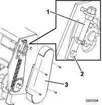
Remove the chain-drive cover (Figure 2).
-
Loosen the 2 hydraulic motor, mount-plate bolts (Figure 2).
-
Using the adjuster bolt, move the hydraulic motor upward to tighten the chain (Figure 2).
-
After you have set the chain to the proper tension, tighten the adjuster bolt and hydraulic motor mount-plate bolts (Figure 2).
Note: When you can no longer set the chain to the proper tension using the adjuster bolt or if chain failures repeatedly occur, replace the chain.
-
Install the chain-drive cover.
Replacing the Tiller Tines
Note: Worn or dull tines degrade the performance of the tiller.
-
Install tines so that there are 2 left tines and 2 right tines on each hub (Figure 3).
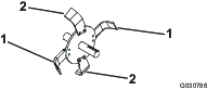
Note: The cutting edges of the tines should face toward the rear of the tiller.
-
Torque the tine-mounting bolts to 85 to 104 N-m (63 to 77 ft-lb).