


Maintenance
Note: Determine the left and right sides of the machine from the normal operating position.
Recommended Maintenance Schedule(s)
| Maintenance Service Interval | Maintenance Procedure |
|---|---|
| After the first operating hour |
|
| After the first 8 operating hours |
|
| After the first 10 operating hours |
|
| After the first 50 operating hours |
|
| Before each use or daily |
|
| Every 50 hours |
|
| Every 100 hours |
|
| Every 150 hours |
|
| Every 200 hours |
|
| Every 250 hours |
|
| Every 400 hours |
|
| Every 800 hours |
|
| Before storage |
|
| Every 2 years |
|
Refer to your engine operator's manual for additional maintenance procedures.
Service Interval Chart
Pre-Maintenance Procedures
Pre-Maintenance Safety
-
Keep all parts of the machine in good working condition and all hardware tightened, especially blade-attachment hardware. Replace all worn or damaged decals.
-
Never allow untrained personnel to service the machine.
-
Before adjusting, cleaning, or repairing the machine, do the following:
-
Move the machine to level ground.
-
Disengage the drives.
-
Lower the cutting units.
-
Move the traction pedal to the NEUTRAL position.
-
Engage the parking brake.
-
Move the throttle switch to the LOW-IDLE position.
-
Shut off the engine and remove the key.
-
Wait for all moving parts to stop.
-
-
Whenever you park or store the machine, or leave it unattended, lower the cutting units unless you use a positive mechanical lock.
-
If possible, do not perform maintenance on the machine while the engine is running. If you must run the engine to perform maintenance on the machine, keep your hands, feet, other body parts, and clothing away from all moving parts, the mower-discharge area, and the underside of the mowers.
-
Do not touch parts of the machine or an attachment that may be hot from operation. Allow the parts to cool before attempting to maintain, adjust, or service them.
-
Use jack stands to support the machine and/or its components when required.
-
Carefully release pressure from components with stored energy.
-
If your machine requires major repairs or if you desire assistance, contact your Toro Distributor.
-
Use only genuine Toro replacement parts and accessories. Replacement parts and accessories made by other manufacturers could be dangerous, and such use could void the product warranty.
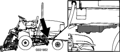
Raising the Machine
Note: Use jack stands to support the machine when required.
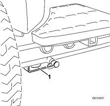
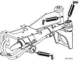
Use the following as points to jack up the machine:
-
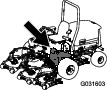
Front of the machine—rectangular pad, under the axle tube, inside each front tire (Figure 26).
-
Rear of the machine—rectangular axle tube on the rear axle.
Lubrication
Greasing the Bearings and Bushings
If you operate the machine under normal conditions, lubricate all grease fittings for the bearings and bushings after every 50 hours of operation with No. 2 lithium grease. Lubricate bearings and bushings immediately after every washing, regardless of the interval listed.
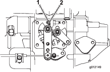
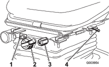
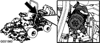
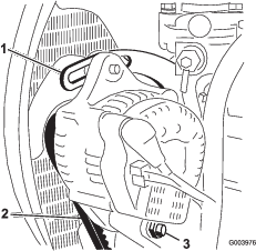
The grease fitting locations and quantities are as follows:
-
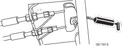
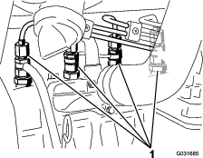
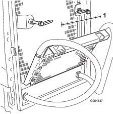
Pump driveshaft U-joint (3) (Figure 27)
-
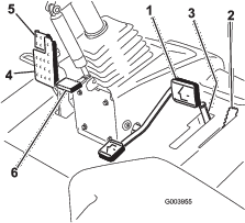
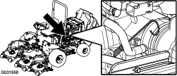
Cutting unit lift-arm cylinders (2 each) (Figure 28)
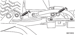
-
Lift-arm pivots (1 each) (Figure 28)
-
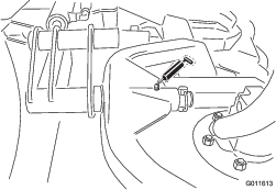
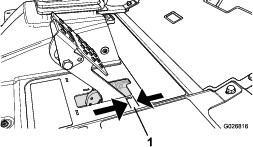
Cutting unit carrier-frame pivot (1 each) (Figure 29)
-
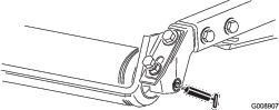
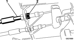
Lift-arm pivot shaft (1 each) (Figure 30)
-
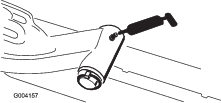
Rear axle tie rod (2) (Figure 31)
-
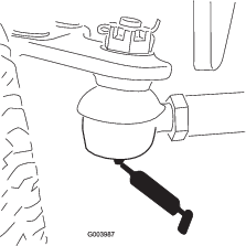
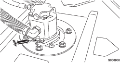
Axle-steering pivot (1) (Figure 32)

-
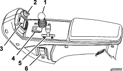
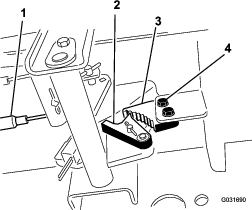
Steering-cylinder ball joints (2) and rear axle (1) (Figure 33)
-
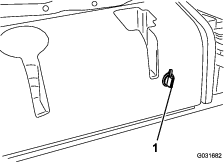
Brake pedal (1) (Figure 34)
-
Cutting unit spindle-shaft bearings (2 per cutting unit) (Figure 35)
Note: Either fitting can be used, which ever is more accessible. Pump grease into the fitting until a small amount appears at bottom of the spindle housing (under the deck).
-
Rear-roller bearings (2 per cutting unit) (Figure 36)
Note: Make sure that the grease groove in each roller mount aligns with the grease hole in each end of the roller shaft. To help align the groove and hole, there is also an alignment mark on 1 end of the roller shaft.
Engine Maintenance
Engine Safety
Shut off the engine before checking the oil or adding oil to the crankcase.
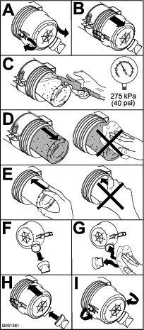
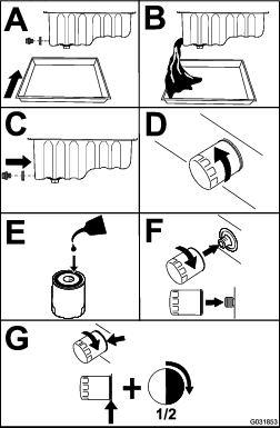
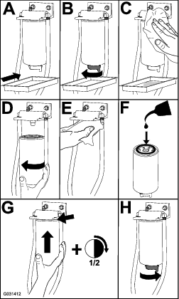
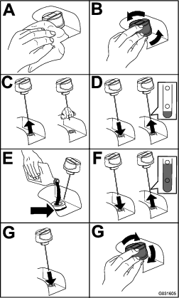
Servicing the Air Cleaner
Check the whole intake system for leaks, damage, or loose hose clamps. Do not use a damaged air filter.
Service the air-cleaner filter only when the service indicator requires it. Changing the air filter before it is necessary only increases the chance of dirt entering the engine when the filter is removed.
Important: Make sure that the cover is seated correctly, seals with the air-cleaner body, and the rubber outlet valve is in a downward position—between the 5 o’clock and 7 o’clock positions when viewed from the end.
Servicing the Engine Oil
Checking the Engine-Oil Level
The engine is shipped with oil in the crankcase; however, the oil level must be checked before and after the engine is first started.
Crankcase capacity is approximately 5.2 L (5.5 US qt) with the filter.
Use high-quality engine oil that meets the following specifications:
-
API Classification Level Required: CH-4, CI-4 or higher
-
Preferred oil: SAE 15W-40 (above -17.8°C (0°F))
-
Alternate oil: SAE 10W-30 or 5W-30 (all temperatures)
Toro Premium Engine oil is available from your distributor in either 15W-40 or 10W-30 viscosity.
-
Park the machine on a level surface, stop the engine, set the parking brake, and remove the key from the ignition switch.
-
Check the engine-oil level (Figure 38).
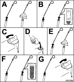
Important: Be sure to keep the engine-oil level between the upper and lower limits on the oil gauge. Engine failure may occur as a result of over filling or under filling the engine oil.
Servicing the Engine Oil and Filter
Important: Do not over-tighten the filter.
Add oil to the crankcase; refer to Checking the Engine-Oil Level.
Close sectionAdjusting the Throttle
-
Position the throttle lever forward so it is approximately 3 mm (1/8 inch) from the front of the control-arm slot.
-
Loosen the throttle cable connector, on the throttle cable, next to the injection-pump lever (Figure 40).
-
Hold the injection-pump lever arm against the high-idle stop (Figure 40).
-
While pulling the throttle cable, to remove any slack, tighten the throttle-cable connector.
Note: When tightened, the cable pivot must be free to swivel on the injection-pump lever arm.
-
If the throttle does not stay in position during operation, increase the torque on the locknut, used to set the friction device on the throttle lever.
Fuel System Maintenance
Servicing the Fuel System
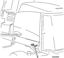
Draining the Fuel Tank
Drain and clean the fuel tank if the fuel system becomes contaminated or if the machine is to be stored for an extended period. Use clean fuel to flush out the tank.
Close sectionChecking the Fuel Lines and Connections
Inspect them for deterioration, damage, or loose connections.
Close sectionServicing the Water Separator
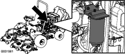
Servicing the Fuel-Pickup Tube
The fuel-pickup tube, located inside the fuel tank, is equipped with a screen to help prevent debris from entering the fuel system. Remove the fuel-pickup tube and clean screen as required.
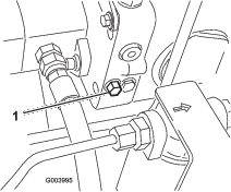
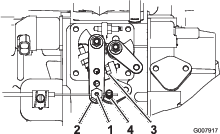
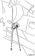
Close sectionBleeding Air from the Fuel Injectors
Note: This procedure should be used only if the fuel system has been purged of air through normal priming procedures and the engine does not start; refer to Bleeding the Fuel System.
-
Loosen the pipe connection to the No. 1 nozzle and holder assembly (Figure 42).
-
Turn the key in the ignition switch to the ON position and watch the fuel flow around the connector.
-
When you observe a solid flow of fuel, turn the key in the ignition switch to the OFF position.
-
Tighten the pipe connector securely.
-
Repeat steps 1 through 4 on the remaining nozzles.
Electrical System Maintenance
Electrical System Safety
-
Disconnect the battery before repairing the machine. Disconnect the negative terminal first and the positive last. Connect the positive terminal first and the negative last.
-
Battery acid is poisonous and can cause burns. Avoid contact with your skin, eyes, and clothing. Protect your face, eyes, and clothing when working with a battery.
-
Battery gases can explode. Keep cigarettes, sparks, and flames away from the battery.
-
Charge the batteries in an open, well-ventilated area, away from sparks and flames. Unplug the charger before connecting or disconnecting the battery. Wear protective clothing and use insulated tools.
-
Do not use a pressure washer near any electronic components.
Warning
Battery posts, terminals, and related accessories contain lead and lead compounds, chemicals known to the State of California to cause cancer and reproductive harm. Wash hands after handling.
Servicing the Battery
Note: To clean the battery, wash the entire case with a solution of baking soda and water. Rinse it with clear water.
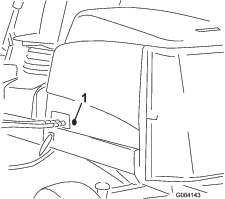
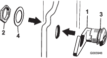
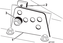
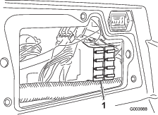
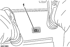
Close sectionReplacing the Fuses
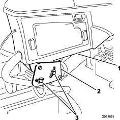
There are 8 fuses in the Electrical System. The fuse block (Figure 43) is located behind the control-arm access panel.

Drive System Maintenance
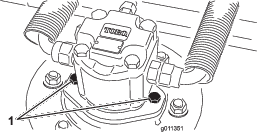
Adjusting the Traction Drive for Neutral
The machine must not creep when the traction pedal is released. If it does creep, adjust as follows:
-
Park the machine on a level surface, stop the engine, and lower the cutting decks to the ground.
-
Jack up the machine until all the tires are off the ground. Support the machine with jack stands to prevent it from falling accidentally.
-
On the right side of the hydrostat, loosen the locknut on the traction adjustment cam (Figure 45).
Warning
The engine must be running so the final adjustment of the traction adjustment cam can be performed. This could cause personal injury.
Keep your hands, feet, face, and other body parts away from the muffler, other hot parts of the engine, and any rotating parts.
-
Turn the key in the ignition switch to the ON position, start the engine, and rotate the cam hex in either direction until the wheels cease rotation.
-
Tighten the locknut to secure the adjustment.
-
Turn the key in the ignition switch to the OFF position, remove the jack stands, and lower the machine to the ground.
-
Test drive the machine to make sure that it does not creep.
Adjusting the Rear Wheel Toe-in
-
Rotate the steering wheel so that the rear wheels are straight ahead.
-
Loosen the jam nut on each end of the tie rod (Figure 46).
Note: The end of the tie rod with the external groove is a left thread.
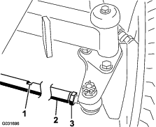
-
Using the wrench slot, rotate the tie rod.
-
Measure the distance at the front and rear of the rear wheels at axle height.
Note: The distance at the front of the rear wheels should be less than 6 mm (1/4 inch) of the distance measured at the rear of the wheels.
-
Repeat procedure as required.
Cooling System Maintenance
Checking the Cooling System
The cooling system is filled with a 50/50 solution of water and permanent ethylene glycol antifreeze. The capacity of the cooling system is 9.5 L (10 US qt).
Caution
If the engine has been running, the pressurized, hot coolant can escape and cause burns.
-
Do not open the radiator cap when the engine is running.
-
Use a rag when opening the radiator cap, and open the cap slowly to allow steam to escape.
-
Check the level of coolant in the expansion tank (Figure 47).
Note: The coolant level should be between the marks on the side of the tank.
-
If the coolant level is low, remove the expansion-tank cap and replenish the system. Do not overfill.
-
Install the expansion-tank cap.
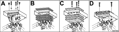
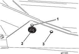
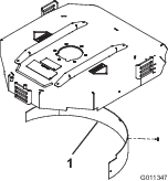
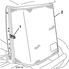
Removing Debris from the Cooling System
-
Turn the key in the ignition switch to the OFF position and remove the key.
-
Thoroughly clean all debris out of the engine area.
-
Unlatch the clamp and pivot open the rear screen (Figure 48).
-
Clean the screen thoroughly with compressed air.
-
Pivot the latches inward to release the oil cooler (Figure 49).
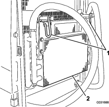
-
Thoroughly clean both sides of the oil cooler and the radiator (Figure 50) with compressed air.
-
Pivot the oil cooler back into position and secure the latches.
-
Close the screen and secure the latch.
Brake Maintenance
Adjusting the Parking Brakes
Adjust the brakes when there is more than 2.5 cm (1 inch) of free travel (Figure 51) of the brake pedal, or when more holding force is required. Free travel is the distance the brake pedal moves before you feel braking resistance.
Note: Use the wheel motor backlash to rock the drums back and forth to ensure that the drums are free prior to and after adjustment.
-
To reduce free travel of the brake pedals, tighten the brakes by loosening the front nut on the threaded end of the brake cable (Figure 52).
-
Tighten the rear nut to move the cable backward until brake pedals have 6.3 to 12.7 mm (1/4 to 1/2 inch) of free travel (Figure 51), before wheel lock up is achieved.
-
Tighten the front nuts, ensuring that both cables actuate the brakes simultaneously. Ensure that the cable conduit does not rotate during tightening procedure.
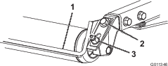
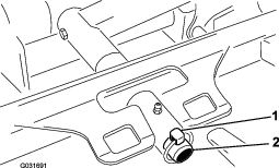
Adjusting the Parking-Brake Latch
If the parking brake fails to engage and latch, an adjustment to the brake pawl is required.
-
Loosen the 2 screws securing the parking-brake pawl to the frame (Figure 53).
-
Press the parking-brake pedal forward until the brake detent completely engages on the brake pawl (Figure 53).
-
Tighten the 2 screws locking the adjustment.
-
Press the brake pedal to release the parking brake.
-
Check the adjustment and adjust as required.
Belt Maintenance
Tensioning the Alternator Belt
-
Open the hood.
-
Check the tension of the alternator belt by depressing it (Figure 54) midway between the alternator and the crankshaft pulleys with 10 kg (22 lb) of force.
Note: The belt should deflect 11 mm (0.04 inch).
-
If the deflection is incorrect, proceed to step 4. If correct, continue operation.
-
Loosen the bolt securing the brace to the engine (Figure 54), the bolt securing the alternator to the brace and the pivot bolt.
-
Insert a pry bar between the alternator and the engine and pry out on the alternator.
-
When you achieve the proper tension, tighten the alternator, brace, and pivot bolts to secure the adjustment.
Hydraulic System Maintenance
Checking the Hydraulic Fluid Level
The machines reservoir is filled at the factory with approximately 56.7 L (15 US gallons) of high quality hydraulic fluid. The recommended replacement fluid is as follows:
| Toro Premium All Season Hydraulic Fluid (Available in 18.9 L (5 US gallon) pails or 208 L (55 US gallon) drums. See the Parts Catalog or your Toro Distributor for part numbers.) |
Alternate fluids: If the Toro fluid is not available, other fluids may be used provided they meet all the following material properties and industry specifications. We do not recommend the use of synthetic fluid. Consult with your lubricant distributor to identify a satisfactory product.
Note: Use products only from reputable manufactures. Toro does not take responsibility for damage caused by improper substitutions.
| High Viscosity Index/Low Pour Point Anti-wear Hydraulic Fluid, ISO VG 46 | |||
| Material Properties: | |||
| Viscosity, ASTM D445 | cSt @ 40°C 44 to 48cSt @ 100°C 7.9 to 8.5 | ||
| Viscosity Index ASTM D2270 | 140 to 160 | ||
| Pour Point, ASTM D97 | -34°F to -49°F | ||
| Industry Specifications: | |||
| Vickers I-286-S (Quality Level), Vickers M-2950-S (Quality Level), Denison HF-0 | |||
Important: The ISO VG 46 Multigrade fluid has been found to offer optimal performance in a wide-range of temperature conditions. For operation in consistently high ambient temperatures, 18°C (65°F) to 49°C (120°F), ISO VG 68 hydraulic fluid may offer improved performance.
Premium Biodegradable Hydraulic Fluid-Mobil EAL EnviroSyn 46H
Important: Mobil EAL EnviroSyn 46H is the only synthetic biodegradable fluid approved by Toro. This fluid is compatible with the elastomers used in Toro hydraulic systems and is suitable for a wide-range of temperature conditions. This fluid is compatible with conventional mineral oils, but for maximum biodegradability and performance the hydraulic system should be thoroughly flushed of conventional fluid. The oil is available in 19 L (5 US gallons) containers or 208 L (55 US gallons) drums from your Mobil Distributor.
Note: Many hydraulic fluids are almost colorless, making it difficult to spot leaks. A red dye additive for the hydraulic system oil is available in 20 ml (2/3 oz) bottles. 1 bottle is sufficient for 15 to 23 L (4 to 6 US gallons) of hydraulic oil. Order Part No. 44-2500 from your Toro Distributor.
-
Position the machine on a level surface, lower the cutting decks, and turn the key in the ignition switch to the OFF position.
-
Check the hydraulic-fluid level (Figure 55).
Changing the Hydraulic Fluid
If fluid becomes contaminated, contact your Toro Distributor because the system must be flushed. Contaminated fluid looks milky or black when compared to clean oil.
-
Turn the key in the ignition switch to the OFF position and raise the hood.
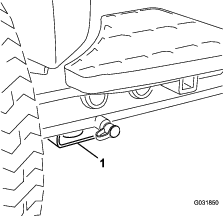
-
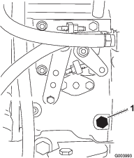
Place a large drain pan under the fitting secured to the bottom of the hydraulic-fluid reservoir (Figure 56).
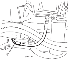
-
Disconnect the hose from the bottom of the fitting and let the hydraulic fluid flow into the drain pan.
-
Install the hose when hydraulic fluid stops draining.
-
Fill the reservoir with approximately 56.7 L (15 US gallons) of hydraulic fluid; refer to Changing the Hydraulic Fluid.
Important: Use only hydraulic fluids specified. Other fluids could cause system damage.
-
Install the reservoir cap.
-
Turn the key in the ignition switch to the ON position, start the engine, use all of the hydraulic controls to distribute hydraulic fluid throughout the system, and check for leaks.
-
Turn the key in the ignition switch to the OFF position.
-
Check the level of the hydraulic fluid and add enough to raise level to the Full mark on the dipstick.
Important: Do not over-fill.
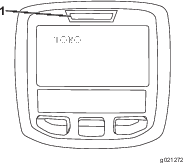
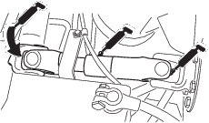
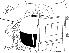
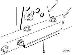
Replacing the Hydraulic Filters
The hydraulic system is equipped with a service-interval indicator (Figure 57). With the engine running, view the indicator, it should be in the green zone. When the indicator is in the red zone, change the hydraulic filters.
Important: Use of any other filters may void the warranty on some components.
-
Position the machine on a level surface, lower the cutting decks, turn the key in the ignition switch to the OFF position, engage the parking brake, and remove the key.
-
Replace both of the hydraulic filters (Figure 58).
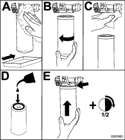
-
Turn the key in the ignition switch to the ON position, start the engine, and let it run for about 2 minutes to purge air from the system.
-
Turn the key in the ignition switch to the OFF position and check for leaks.
Checking the Hydraulic Lines and Hoses
Make all necessary repairs before operating.
Warning
Hydraulic fluid escaping under pressure can penetrate skin and cause injury.
-
Make sure that all hydraulic-fluid hoses and lines are in good condition and all hydraulic connections and fittings are tight before applying pressure to the hydraulic system.
-
Keep your body and hands away from pin hole leaks or nozzles that eject high-pressure hydraulic fluid.
-
Use cardboard or paper to find hydraulic leaks.
-
Safely relieve all pressure in the hydraulic system before performing any work on the hydraulic system.
-
Get immediate medical help if fluid is injected into skin.
Testing the Pressure in the Hydraulic System
Use the hydraulic system test ports to test the pressure in the hydraulic circuits. Contact your Toro Distributor for assistance.
Close sectionHydraulic Valve Solenoid Functions
Use the list below to identify and describe the different functions of the solenoids in the hydraulic manifold. Each solenoid must be energized to allow function to occur.
| Solenoid | Function |
|---|---|
| PRV2 | Front mower circuit |
| PRV1 | Rear mower circuit |
| PRV | Lift/lower cutting decks |
| S1 | Lower cutting decks |
| S2 | Lower cutting decks |
Separating the Cutting Decks from the Traction Unit
-
Position the machine on a level surface, lower the cutting decks to the floor, turn the key in the ignition switch to the OFF position, and engage the parking brake.
-
Disconnect and remove the hydraulic motor from the deck (Figure 59). Cover the top of the spindle to prevent contamination.
-
Remove the lynch pin securing the deck-carrier frame to the lift-arm pivot pin (Figure 60).
-
Roll the cutting deck away from the traction unit.
Mounting the Cutting Decks to the Traction Unit
-
Position the machine on a level surface and turn the key in the ignition switch to the OFF position.
-
Move the cutting deck into position in front of the traction unit.
-
Slide the deck-carrier frame onto the lift-arm pivot pin and secure it with the lynch pin (Figure 60).
-
Install the hydraulic motor to the deck (Figure 59). Make sure that the O-ring is in position and not damaged.
-
Grease the spindle.
Blade Safety
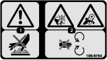
Danger
A worn or damaged blade can break, and a piece of the blade could be thrown at you or bystanders, resulting in serious personal injury or death. Trying to repair a damaged blade may result in discontinued safety certification of the product.
-
Inspect the blade periodically for wear or damage.
-
Never try to straighten a blade that is bent or weld a broken or cracked blade.
-
Replace a worn or damaged blade.
-
Use care when checking the blades. Wrap the blades or wear gloves, and use caution when servicing the blades. Only replace the blades; never straighten or weld them.
-
On multi-bladed machines, take care as rotating 1 blade can cause other blades to rotate.
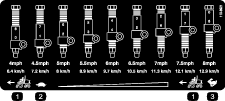
Servicing the Blade Plane
The rotary deck comes from the factory preset at 5 cm (2 inches) height of cut and blade rake of 7.9 mm (0.310 inch). The left and right heights are also preset to within 0.7 mm (0.030 inch) of the other.
The cutting deck is designed to withstand blade impacts without deformation of the chamber. If a solid object is struck, inspect the blade for damage and the blade plane for accuracy.
Inspecting the Blade Plane
-
Remove the hydraulic motor from the cutting deck and remove the cutting deck from the tractor.
-
Use a hoist (or minimum of 2 people) and place the cutting deck on a flat table.
-
Mark 1 end of the blade with a paint pen or marker. Use this end of the blade to check all heights.
-
Position the cutting edge of the marked end of the blade at 12 o’clock (straight ahead in the direction of mowing) (Figure 61) and measure height from table to cutting edge of blade.
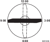
-
Rotate the marked end of the blade to the 3 and 9 o’clock positions (Figure 61) and measure the heights.
-
Compare the 12 o’clock measured height to the height-of-cut setting. It should be within 0.7 mm (0.030 inch). The 3 and 9 o’clock heights should be 1.6 to 6.0 mm (0.06 to 0.24 inch) higher than the 12 o’clock setting and within 1.6 to 6.0 mm (0.06 to 0.24 inch) of each other.
Note: If any of these measurements are not within specification, proceed to Adjusting the Blade Plane.
Close sectionAdjusting the Blade Plane
Start with the front adjustment (change 1 bracket at a time).
-
Remove the height-of-cut bracket (front, left, or right) from the deck frame (Figure 62).
-
Adjust 1.5 mm (0.060 inch) shims and/or 0.7 mm (0.030 inch) shim between the deck frame and bracket to achieve the desired height setting (Figure 62).
-
Install the height-of-cut bracket to the deck frame with the remaining shims assembled below the height-of-cut bracket.
-
Secure the socket-head bolt/spacer and flange nut.
Note: Socket-head bolt/spacer are held together with thread-locking adhesive to prevent the spacer from falling inside the deck frame.
-
Verify the 12 o’clock height and adjust if needed.
-
Determine if only 1 or both (right and left) height-of-cut brackets need to be adjusted. If the 3 or 9 o’clock side is 1.6 to 6.0 mm (0.06 to 0.24 inch) higher than the new front height then no adjustment is needed for that side. Adjust the other side to within 1.6 to 6.0 mm (0.06 to 0.24 inch) of the correct side.
-
Adjust the right and/or left height-of-cut brackets by repeating steps 1 through 3.
-
Secure the carriage bolts and flange nuts.
-
Again, verify the 12, 3, and 9 o’clock heights.
Removing and Installing a Blade
Replace the blade if a solid object is hit, the blade is out of balance, or if the blade is bent. Always use genuine Toro replacement blades to be sure of safety and optimum performance. Never use replacement blades made by other manufacturers because they could be dangerous.
-
Raise the cutting deck to the highest position, turn the key in the ignition switch to the OFF position, and engage the parking brake. Block the cutting deck to prevent it from falling accidentally.
-
Grasp the end of the blade using a rag or thickly padded glove. Remove the blade bolt, anti-scalp cup, and blade from the spindle shaft (Figure 63).

-
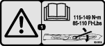
Install the blade, sail facing toward the cutting deck, with the anti-scalp cup and blade bolt (Figure 63). Tighten the blade bolt to 115 to 149 N∙m (85 to 110 ft-lb).
Inspecting and Sharpening the Blade
-
Raise the cutting deck to the highest position, turn the key in the ignition switch to the OFF position, and engage the parking brake.
-
Block the cutting deck to prevent it from falling accidentally.
-
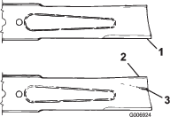
Examine the cutting ends of the blade carefully, especially where the flat and curved parts of the blade meet (Figure 64).
Note: Since sand and abrasive material can wear away the metal that connects the flat and curved parts of the blade, check the blade before using the machine.
-
If wear is noticed (Figure 64), replace the blade; refer to Servicing the Blade Plane.
Danger
If the blade is allowed to wear, a slot will form between the sail and flat part of the blade (Figure 63). Eventually a piece of the blade may break off and be thrown from under the housing, possibly resulting in serious injury to yourself or bystanders.
-
Inspect the blade periodically for wear or damage.
-
Always replace a worn or damaged blade.
-
-
Inspect the cutting edges of all blades. Sharpen the cutting edges if they are dull or nicked. Sharpen only the top of the cutting edge and maintain the original cutting angle to make sure that it is sharp (Figure 65).
-
If dull or nicked, sharpen only the top cutting edge while maintaining the original cutting angle (Figure 65).
Note: The blade will remain balanced if the same amount of metal is removed from both cutting edges.

-
To check the blade for being straight and parallel, lay the blade on a level surface and check its ends.
Note: Position the ends of the blade slightly lower than the center, and the cutting edge lower than the heel of the blade. This blade produces a good quality of cut and requires minimal power from the engine. By contrast a blade that is higher at the ends than the center, or if cutting edge is higher than the heel, the blade is bent or warped and must be replaced.
-
Install the blade, sail facing toward cutting deck, with the anti-scalp cup and blade bolt. Torque the blade bolt to 115 to 149 N∙m (85 to 110 ft-lb).
Servicing the Front Roller
Inspect the front roller for wear, excess wobble, or binding. Service or replace the roller or components if any of these conditions exist.
Disassembling the Front Roller
-
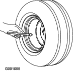
Remove the roller-mounting bolt (Figure 66).
-
Insert a punch through the end of the roller housing and drive the opposite bearing out by alternating taps to the opposite side of inner bearing race. There should be a 1.5 mm (0.060 inch) lip of inner race exposed.

-
Push the second bearing out in press.
-
Inspect the roller housing, bearings, and bearing spacer for damage (Figure 66).
-
Replace damaged components and assemble.
Assembling the Front Roller
-
Press the first bearing into the roller housing (Figure 66). Press on the outer race only or equally on the inner and outer race.
-
Insert the spacer (Figure 66).
-
Press the second bearing into the roller housing (Figure 66). Pressing equally on the inner and outer race until the inner race comes in contact with the spacer.
-
Install the roller assembly into the deck frame.
-
Verify that there is no more than a 1.5 mm (0.060 inch) gap between roller assembly and the roller-mount brackets of the deck frame.
-
If there is a gap over 1.5 mm (0.060 inch), install enough 5/8 inch diameter washers to take up the slop.
Important: Securing the roller assembly with a gap larger than 1.5 mm (0.060 inch) creates a side load on the bearing and can lead to premature bearing failure.
-
Torque the mounting bolt to 108 N∙m (80 ft-lb).