Installation
Preparing the Machine
Note: Retain all removed parts for later installation unless otherwise noted.
-
Park the machine on a level surface, shift the transmission into the NEUTRAL position (manual) or the PARK position (automatic) and engage the parking brake.
-
Shut off the engine, remove the key (if equipped), disconnect the battery, and allow the engine to cool.
-
Tilt the passenger seat forward and align the prop rod into the detent in the prop-rod-guide slot.
-
Drain the fuel tank; refer to your machine Operator’s Manual.
-
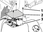
Remove the 4 screws securing the cover and remove it (Figure 1).
Note: You may discard the cover.
-
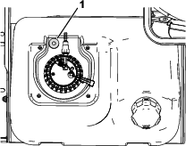
Under the cover, place the bushing as shown in Figure 2 and mark the center on the fuel tank.
-
Remove the fuel pump from the machine; refer to your machine Operator’s Manual .
-
Insert a rag inside the tank through the opening for the fuel pump to catch any debris.
-
Drill a 17/32 inch diameter hole in top of the fuel tank at the location marked in step 7 and clean up the opening and remove the rag and any debris.
Connecting the Canister to the Fuel Tank
Parts needed for this procedure:
| Canister bracket | 1 |
| Grommet (9/16 inch) | 2 |
| Carbon canister | 1 |
| Canister clamp | 1 |
| Bushing | 1 |
| Elbow fitting | 1 |
| Hose (10-1/2 inches) | 1 |
| Straight fitting (3/16 to 1/4 inch) | 1 |
| Hose (25 inches) | 1 |
| Hose clamp (13/32 inch) | 2 |
| Hose clamp (1/2 inch) | 2 |
-
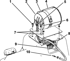
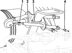
Assemble the carbon canister, canister clamp, and 2 grommets (9/16 inch) to the canister bracket (Figure 3)
Note: Ensure that the inlets on the canister face the front of the machine and point down.
-
Route a 10-1/2 inch hose through the bracket to the center canister inlet marked TANK and secure it with a hose clamp (1/2 inch).
-
Route the 25 inch hose through the bracket to the outer canister inlet marked PURGE and secure it with a hose clamp (13/32 inch).
-
Install the bushing to the hole drilled in Preparing the Machine.
-
Install the canister bracket assembly with the screws removed in Preparing the Machine
-
Connect the free end of the 25 inch hose to the small end of a straight fitting (3/16 to 1/4 inch) with a hose clamp (13/32 inch).
-
Connect the free end of the 10-1/2 inch hose from the canister to the small end of the elbow fitting with a hose clamp (1/2 inch).
-
Connect the large end of the elbow fitting to the bushing.
Connecting the Vacuum-Control Valve and Valve Bracket
Parts needed for this procedure:
| Valve bracket | 1 |
| Grommet (1/2 inch) | 4 |
| Vacuum-control valve | 1 |
| Hose (10-1/2 inches) | 2 |
| Straight fitting (3/16 to 1/4 inch) | 1 |
| Straight fitting (1/4 to 5/16 inch) | 1 |
| Hose (9 inches) | 1 |
| Hose clamp (13/32 inch) | 2 |
| Hose clamp (1/2 inch) | 4 |
| Cable tie | 1 |
-
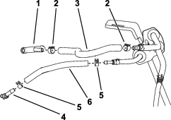
Assemble 4 grommets (1/2 inch) to the valve bracket.
-
Route 2 hoses (10-1/2 inches) through the 2-hole tab on the valve bracket to the 2 large inlets on the vacuum-control valve.
-
Secure the hoses to the vacuum-control valve with hose clamps (1/2 inch).
-
Connect the loose end of the lower hose on the vacuum-control valve to the straight fitting on the end of the 25 inch hose and secure it with a hose clamp (1/2 inch).
-
Connect the loose end of the upper hose on the vacuum-control valve to the small end of the straight fitting (1/4 to 5/16 inch) and secure it with a hose clamp (1/2 inch).
-
Route the 9 inch hose through the 1-hole tab on the valve bracket to the remaining inlet on the vacuum-control valve.
-
Secure the 9 inch hose to the vacuum-control valve with a hose clamp (13/32).
-
Connect the loose end of the 9 inch hose to the small end of a straight fitting (3/16 to 1/4 inch) with a hose clamp (13/32 inch).
-
Secure the valve bracket assembly to the support bar that extends from the frame with a cable tie (Figure 5).
Completing the Installation
Parts needed for this procedure:
| Hose (10-1/2 inches) | 1 |
| Hose (9-1/2 inches) | 1 |
| T-fitting (1/2 x 1/2 x 5/16 inch) | 1 |
| T-fitting (1/4 x 1/4 x 1/4 inch) | 1 |
| Hose clamp (1/2 inch) | 4 |
| Hose clamp (5/16 inch) | 2 |
| Hose clamp (13/16 inch) | 2 |
| Fuel cap | 1 |
-
Connect the 10-1/2 inch hose to the straight fitting on the 9 inch hose from the vacuum-control valve and secure it with a hose clamp (1/2 inch).
-
Connect the loose end of the 10-1/2 inch hose to the center branch of the 1/4 x 1/4 x 1/4 inch T-fitting and secure it with a hose clamp (1/2 inch).
-
Connect the 9-1/2 inch hose to the straight fitting on the upper hose from the vacuum-control valve and secure it with a hose clamp (5/16 inch).
-
Connect the loose end of the 9-1/2 inch hose to the center branch of the 1/2 x 1/2 x 5/16 inch T-fitting and secure it with a hose clamp (5/16 inch).
-
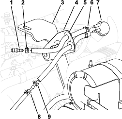
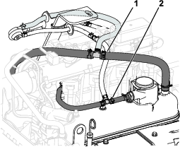
Position the 1/4 x 1/4 x 1/4 inch T-fitting along the short PCV hose extending from the top of the engine and cut the hose where appropriate to install the T-fitting.
Note: Cut the PCV hose about 3 inches away from its connection to the engine.
-
Connect the 1/4 inch branches of the T-fitting to the cut ends of the PCV hose with hose clamps (1/2 inch) as shown in Figure 7.
-
Position the 1/2 x 1/2 x 5/16 inch T-fitting along the long vacuum hose extending from the top of the engine and cut the hose where appropriate to install the T-fitting.
Note: Cut the PCV hose about 10-1/2 inches away from itsconnection to the engine.
-
Connect the 1/2 inch branches of the T-fitting to the cut ends of the vacuum hose with hose clamps (13/16 inch) as shown in Figure 7.
-
Install the new fuel cap to the fuel tank.
-
Connect the battery and fill the fuel tank; refer to your machine Operator’s Manual.