Introduction
Visit www.Toro.com for product safety and operation training materials, accessory information, help finding a dealer, or to register your product.
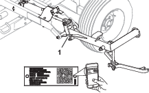
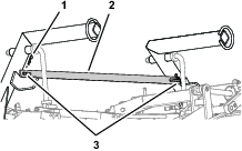
Whenever you need service, genuine Toro parts, or additional information, contact an Authorized Service Dealer or Toro Customer Service and have the model and serial numbers of your product ready. Figure 1 identifies the location of the model and serial numbers on the product. Write the numbers in the space provided.
Important: With your mobile device, you can scan the QR code (if equipped) on the serial number plate to access warranty, parts, and other product information.
Setup
Preparing the Machine
Parking the Machine
-
Park the reel frame on a level surface and lower the cutting units to the ground.
-
Engage the parking brake, shut off the engine, remove the key, and wait for all moving parts to stop.
-
Chock the wheels of the reel frame to ensure that the machine does not move.
Disconnecting the Hydraulic Hoses
Hydraulic System Safety
-
Seek immediate medical attention if fluid is injected into skin. Injected fluid must be surgically removed within a few hours by a doctor.
-
Ensure that all hydraulic-fluid hoses and lines are in good condition and all hydraulic connections and fittings are tight before applying pressure to the hydraulic system.
-
Keep your body and hands away from pinhole leaks or nozzles that eject high-pressure hydraulic fluid.
-
Use cardboard or paper to find hydraulic leaks.
-
Safely relieve all pressure in the hydraulic system before performing any work on the hydraulic system.
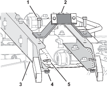
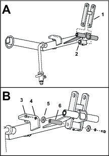
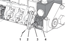
Installing the Fittings to the Control Valves
Parts needed for this procedure:
| Short 90° fitting | 2 |
| Tall 90° fitting | 2 |
-
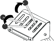
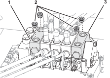
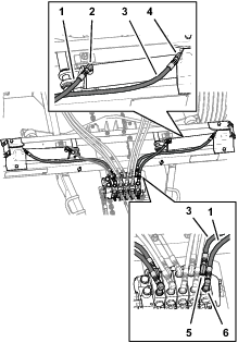
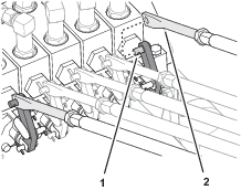
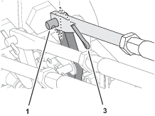
Remove the socket-head plugs from the cutting-unit 6 and the cutting-unit 7 control valves (Figure 4).
-
Lubricate the O-rings of the 4 90° hydraulic fittings with clean hydraulic fluid.
-
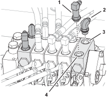
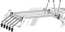
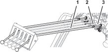
Assemble the short 90° fittings into the retract ports of the cutting-unit 6 and the cutting-unit 7 control valves (Figure 5).
-
Assemble the tall 90° fittings into the extend ports of the cutting-unit 6 and the cutting-unit 7 control valves (Figure 5).
-
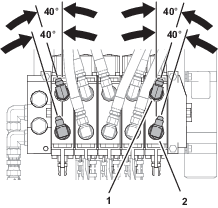
Align the 90° fittings as shown in Figure 6, and tighten the jam nuts.
Installing the Lift Cylinders
Parts needed for this procedure:
| 90° fitting (3/8 inch—tapered-pipe thread) | 4 |
| Lift cylinder | 2 |
| Cylinder rest | 2 |
| Capscrew (1/2 x 1-1/2 inches) | 4 |
| Tapered washer | 4 |
| Flange locknuts (1/2 inch) | 4 |
| Spacer tube | 4 |
| Cotter pin (3/16 x 1-3/4 inches) | 4 |
| Lift-arm stop | 2 |
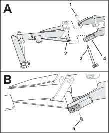
Preparing the Cylinders
Installer supplied material: #2 Permatex™ gasket sealant
-
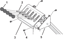
Apply a coat of No. 2 Permatex gasket sealant to the threads of the 4 90° fittings with 3/8 inch tapered-pipe threads.
-
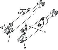
Assemble the 90° fittings into the extend and retract ports of the lift cylinders (Figure 7).
-
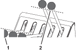
Tighten the 90° fittings at a 45° angel to the body of the cylinders as shown in Figure 7.
-
Use a piece of tape to mark the lift cylinders 6 and 7.
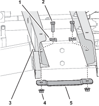
Installing the Cylinder Rest
-
Align the holes in the cylinder rest with the 12.7 mm (1/2 inch)–diameter holes in the bottom of the cross channels (Figure 8)
-
Secure the cylinder rest to the cross channels (Figure 8) with the 2 capscrews (1/2 x 1-1/2 inches), 2 tapered washers, and 2 flange locknuts (1/2 inch).
-
Repeat steps 1 and 2 for the other cylinder rest at the other side of the machine.
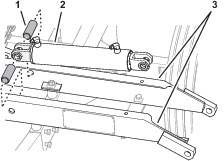
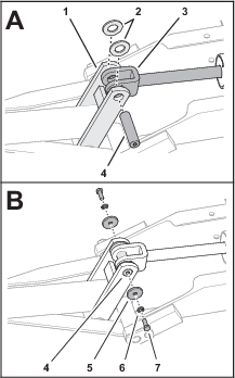
Assembling the Lift Cylinders to the Machine
-
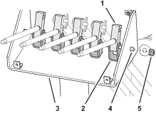
Align the holes in the 2 spacer tubes and the holes in the flanges of the cutting-unit 6 lift cylinder with the 25 mm (1 inch)-diameter holes in the top of cross channels (Figure 9).
-
Assemble the shaft—25 x 305 mm (1 x 12 inches) through the spacer tubes and the cylinder-body flanges (Figure 10).
-
Secure the shaft to the cross channels (Figure 10) with 2 cotter pins (3/16 x 1-3/4 inches).
-
Repeat steps 1 through 3 for the cutting-unit 7 lift cylinder at the other side of the machine.
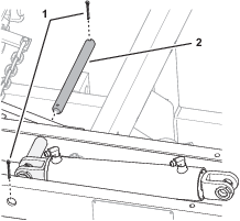
Installing the Lift-Arm Stop
-
Align the holes in the lift-arm stop with the 12.7 mm (1/2 inch)–diameter holes in the top of the cross channels as shown in Figure 11.
-
Secure the lift-arm stop to the cross channels (Figure 11) with the 2 capscrews (1/2 x 1-1/2 inches), 2 tapered washers, and 2 flange locknuts (1/2 inch).
-
Repeat steps 1 and 2 for the lift-arm stop at the other side of the machine.
Preparing the Lift Arms
Parts needed for this procedure:
| Link | 2 |
| Shaft—25 x 102 mm (1 x 4 inches) | 2 |
| Washer (3/8 x 1-5/8 inches) | 4 |
| Lock washer (3/8 inch) | 4 |
| Capscrew (3/8 x 1 inch) | 4 |
-
Align the holes in the link with the hole in the bushing housing of the lift arm as shown in Figure 12.
-
Assemble the shaft—25 x 102 mm (1 x 4 inches) through the holes in the link and the bushing housing (Figure 12).
-
Secure the shaft to the link with (Figure 12) 2 capscrews (3/8 x 1 inch), 2 lock washers (3/8 inch), and 2 washers (3/8 x 1-5/8 inches).
-
Repeat steps 1 through 3 for the other lift arm and link.
Installing the Lift Arms and Draw Bars
Parts needed for this procedure:
| Locknut (3/4 inch) | 2 |
| Lift-bail pin | 2 |
| Capscrew (5/16 x 3/4 inch) | 2 |
| Washer (1-1/8 x 2 inches) | 4 |
| Shaft—25 x 102 mm (1 x 4 inches) | 2 |
| Capscrew (3/8 x 1 inch) | 4 |
| Lock washer (3/8 inch) | 4 |
| Washer (3/8 x 1-5/8 inches) | 4 |
| Drawbar | 2 |
| Capscrew (1/2 x 4 inches) | 2 |
| Locknut (1/2 inch) | 2 |
Assembling the Lift Arm to the Machine
-
Align the hole in the lift-arm tube with the holes in the arm brackets of the cross channels (Figure 13).
-
Loosely assemble the lift arm to the cross channels with (Figure 13) the lift-bail pin and the locknut (3/4 inch).
-
Align the hole in the tab of the lift-bail pin with the threaded hole in the arm bracket (Figure 13), and secure the pin to the bracket with a capscrew (5/16 x 3/4 inch).
-
Torque the locknut (3/4 inch) to 91 to 113 N∙m (67 to 83 ft-lb).
-
Repeat steps 1 through 4 for the lift arm at the other side of the machine.
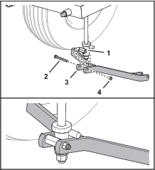
Assembling the Lift Cylinder to the Lift Arm
-
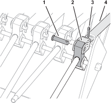
Align the holes in the link, washers (1-1/8 x 2 inches), and the fitting of the lift-cylinder rod (Figure 14).
-
Assemble the shaft—25 x 102 mm (1 x 4 inches) through the holes in the link washers, cylinder-rod fitting (Figure 14).
-
Secure the shaft to the link with (Figure 14) 2 capscrews (3/8 x 1 inch), 2 lock washers (3/8 inch), and 2 washers (3/8 x 1-5/8 inches).
-
Repeat steps 1 through 3 for the lift arm at the other side of the machine.
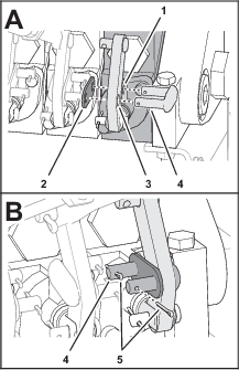
Installing the Drawbar
-
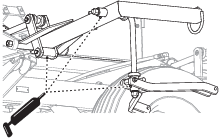
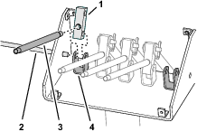
Align the holes in the drawbar with the holes on the pivot housing of the lift bail (Figure 15).
Note: When installing the drawbar, the offset hole in the drawbar should be positioned up and the lift bail stop should be on the top of the drawbar
-
Assemble the drawbar to the lift bail (Figure 15) with a capscrew (1/2 x 4 inches), and locknut (1/2 inch)
-
Tighten the locknut.
Note: Ensure that the drawbar can freely pivot.
-
Lubricate the 3 grease fittings for the lift arm and pivot housing (Figure 16).
-
Repeat steps 1 through 4 for the drawbar at the other side of the machine.
Adjusting the Transport Position for Cutting Units 6 and 7
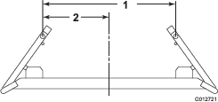
Important: If the transport frame is transported on a public road, the overall width of the frame and the mowers may not exceed 2.4 m (8 ft).
Adjust the mounting position of the clevis on the end of the lift cylinders and the mounting position of the arm stops to the desired width shown in Figure 17.
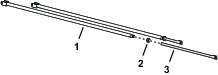
Installing the Hydraulic Hoses
Parts needed for this procedure:
| Hose (long) | 2 |
| Hose (short) | 2 |
-
Install the long hose between the short 90° fitting in the control valve and the 90° fitting in the retract port of the lift cylinder (
-
Install the short hose between the long 90° fitting in the control valve and the 90° fitting in the retract port of the lift cylinder (Figure 18).
-
Repeat steps 1 and 2 for the hoses of the other lift cylinder.
Assembling the Transport Strap to the Machine
Parts needed for this procedure:
| Transport strap | 1 |
| Hairpin | 2 |
-
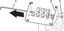
Remove the 2 hair pins that secure the transport strap for the cutting-unit 4 and the cutting-unit 5 lift arms (Figure 19).
-
Assemble the transport strap of the 5 to 7 conversion kit onto the pins of the center frame channel (Figure 19).
-
Insert the 2 hair pins that you removed in 1 and the 2 hair pins from the 5 to 7 conversion kit into the studs (Figure 19).
Assembling the Control Lever to the Control Valve
Parts needed for this procedure:
| Control lever | 2 |
| Clevis pin | 2 |
| Cotter pin | 6 |
| Link plate | 2 |
| Link plate | 2 |
-
Align the hole in the control lever with the holes in the fork of the control valve for cutting-unit 6 (Figure 20).
-
Assemble the lever to the fork with the clevis pin and cotter pin (Figure 20).
-
Assemble the link through the holes in the mounting tab of the control valve and the control lever (Figure 21).
-
Secure the link to the valve and lever with the link plate and 2 cotter pins (Figure 21).
-
Repeat steps 1 through 4 for the control valve of cutting-unit 7.
Preparing the Control Rods
Installing the Lever Blocks
Parts needed for this procedure:
| Lever | 2 |
| Lever block | 2 |
Removing the Control-Console Cover
Installing the Lever Blocks and Levers
-
Remove the locknut that secures the pivot pin to the control console, and remove the pin (Figure 24).
-
Assemble a lever into a lever block (Figure 25).
-
Align the hole in the lever block with the holes in the leftmost control-link bracket (Figure 25).
-
Insert the pivot pin through the holes in the 4 the control-link brackets and lever blocks.
-
Repeat steps 2 through 4 for the lever and lever block for the rightmost control-link bracket.
-
Insert the pivot pin through the holes in the rightmost control-link bracket, lever blocks, and the control console (Figure 26).
-
Secure the pivot pin to the console with the locknut (Figure 26).
Installing the Control Rods
Parts needed for this procedure:
| Clevis pin | 2 |
| Cotter pin | 4 |
Assembling the Control Rod to the Machine
-
At the control console, align the holes in the fork of the control rod with the hole in the lever block (Figure 27).
-
Secure the rod to the block with a clevis pin and cotter pin (Figure 27).
-
At the control valve, assemble the control-rod link onto the clevis pin that is pressed into the control lever (Figure 28).
Note: Do not install the cotter pin.
-
Compare the alignment of the lever for the control rod that you are installing with the levers for cutting-unit 4, cutting-unit 1, 2, and 3, and cutting-unit 5 (Figure 29).
-
If the lever for the control rod is not aligned with the rest of the levers, separate the control-rod link from the control lever clevis pin, rotate the control-rod link to align the lever (Figure 29), and assemble the control-rod link to the control lever clevis pin (Figure 28).
-
Repeat steps 1 through 5 for the other control rod.
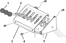
Installing the Control-Console Cover
-
Align the cover over the levers (Figure 30).
-
Align the holes in the cover with the hole in the weld nuts of the control console.
-
Secure the cover to the console (Figure 30) with the 4 flange-head screws that you removed in Removing the Control-Console Cover.
-
Thread the 3 knobs that you removed in Removing the Control-Console Cover and the 2 knobs from the 5 to 7 conversion kit onto the levers (Figure 30).
-
Check the control levers by moving them to the raise and lower positions. Ensure that all levers move freely. Readjust control-rod link if necessary.
-
At the control valve, secure the control-rod link to the control lever with a cotter pin (Figure 32).
-
Tighten the nut (7/16 inch) on the control rod and link; refer to (Figure 33).
-
Repeat steps 6 and 7 for the other side of the machine.
Installing the Reelmaster Cutting Units
-
Align the holes in the drawbar with the holes in the brackets on the cross-tubes of the cutting units.
-
Secure each side (Figure 34) with a bolt (1/2 x 3-1/2 inch), spacer tube, and locknut (1/2 inch).
Important: Position the head of the bolt inboard.
Note: If you are installing Spartan mowers to the transport frame, use drawbar clamp Part No. 5-1090. Mounting fasteners are needed to mount the drawbar to the front of the mower cross tube. Contact your local authorized Toro distributor for assistance.
-
If you installed 18-inch wheels on the cutting units, use Toro Conversion Kit, Part No. 51-3060 to allow the cutting units to raise to the transport position. Contact your local authorized Toro distributor for assistance.
-
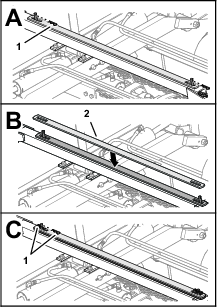
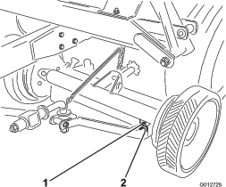
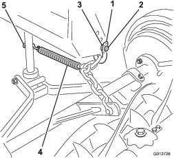
Secure the lift chain to the lift arm and the cutting unit mounting bracket with the long shackles, clevis pins and cotter pins (Figure 35).
Note: Ensure that there are no kinks or twists in the chain.
-
Hook the spring to the fifth link in the chain from the cutting unit, and secure the other end of the spring to the lift bail with the S-hook (Figure 35).
-
Repeat steps 1 through 5 at the other side of the machine.
Connecting the Transport Frame Hoses to the Tow Vehicle
-
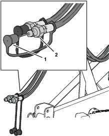
Remove the dust caps from the transport frame hydraulic hoses.
-
Attach the hydraulic hose couplers to the tow vehicle.
-
Start the engine.
-
Raise and lower the cutting units.
Important: Do not operate the transport frame-lift system and deplete the hydraulic fluid of the of the tow vehicle; pump cavitation may occur.
-
Lower the cutting units, shut off the engine, remove the key, and wait for all moving parts to stop.
-
If needed, refill the hydraulic reservoir with fluid recommended for tow vehicle, or use ISO 68 or hydraulic fluid like Mobil 424.
Operation
Securing Cutting-Unit Arms for Transport
-
Fully raise all mowers are to the transport position before moving to the next mowing area.
-
Remove the hairpins securing the transport straps to the pins of the center frame channel and remove the straps.
-
Assemble the transport strap onto the lift-arm pins and secure the straps with the 2 hairpins.
-
Repeat step 3 for the other pair of lift arms.
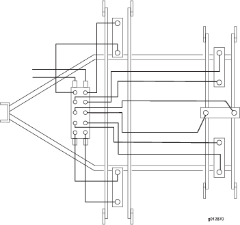
Schematics
Hydraulic Schematic