
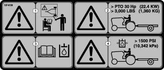
 ), which means Caution,
Warning, or Danger—personal safety instruction. Failure to comply
with these instructions may result in personal injury or death.
), which means Caution,
Warning, or Danger—personal safety instruction. Failure to comply
with these instructions may result in personal injury or death.

Maintenance
Recommended Maintenance Schedule(s)
| Maintenance Service Interval | Maintenance Procedure |
|---|---|
| Every 50 hours |
|
Maintenance Safety
-
Before cleaning, servicing, or adjusting the machine, do the following:
-
Park the tow vehicle and machine on a level surface.
-
Shut off the tow vehicle engine, remove the key, and wait for all moving parts to stop.
-
Chock the wheels.
-
Remove the machine from the tow vehicle.
-
-
Perform only those maintenance instructions described in this manual. If major repairs are ever needed or you need assistance, contact an authorized Toro distributor.
-
Support the machine with blocks or jack stands when working beneath it.
-
Ensure that all guards are installed securely after maintaining or adjusting the machine.
-
Do not allow untrained personnel to service the machine.
-
Keep all parts in good working condition and all fasteners tightened. Replace all damaged or missing decals.
-
Do not interfere with the intended function of a safety device or reduce the protection provided by a safety device. Check their proper operation regularly.
-
Altering this machine in any manner may affect the operation of the machine, performance, durability, or its use may result in injury or death. Such use could void the product warranty of The Toro® Company.
Lubrication
| Maintenance Service Interval | Maintenance Procedure |
|---|---|
| Every 50 hours |
|
Grease Specification
| Grease Type | Use |
| No. 2 lithium base grease | Hydraulic frame fittings |
| SAE 30 engine oil | Wear or friction points |
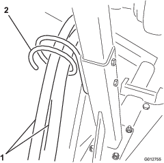
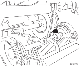
Greasing the Hydraulic Frame Fittings
There are 27 grease fittings on the transport frame. Clean the grease fittings with a clean rag prior to greasing to ensure that no foreign matter is forced into the bushings with the lubricant. While applying grease, ensure that the bushings are taking grease. Apply lubricant to the fitting until some of the grease comes out from the sides of the bushings.
Oiling the Wear and Friction Points
Lightly oil wear or friction points whenever grease fittings are being serviced.
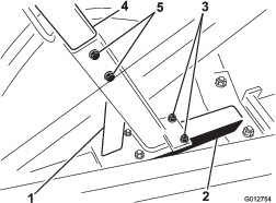
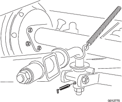
Changing the Hydraulic Fluid
Drain and replace the transport frame hydraulic fluid whenever the tow vehicle fluid is changed, if the fluid is not compatible with the tow vehicle fluid, or if the fluid becomes contaminated.
-
Start the tow vehicle, remove all cutting units, raise the lift arms until all lift cylinders are fully retracted, and then shut off the tow vehicle.
-
Disconnect the supply and return hose couplers from the tow vehicle couplers.
-
Disconnect the supply and return hoses from the transport frame control valve and drain the hoses into a drain pan.
-
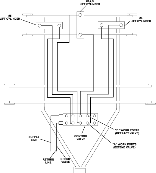
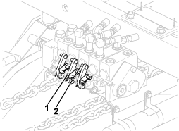
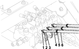
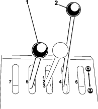
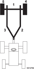
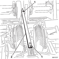
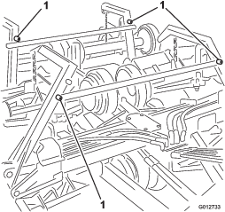
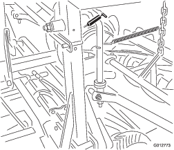
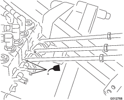
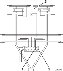
Disconnect the hydraulic hoses connected to the front row of the control valve, Row "A" (Figure 34). Drain each hose into a drain pan and reconnect them to the corresponding valves.
-
Disconnect the hydraulic hoses that are connected to the back row of the control valve, Row "B" (Figure 34). Drain each line and cylinder by carefully pulling down the lift arms until all fluid is pumped out of the hoses and cylinders and into a drain pan. Reconnect the hoses to the control valve.
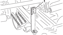
Note: #1 cylinder is not connected to a lift arm to aid in draining the cylinder. Extend the cylinder by using a winch or other pulling device.
-
Connect the supply and return hoses to the transport frame control valve.
-
Fill the tow vehicle hydraulic-fluid reservoir to the appropriate level using the correct fluid; refer to the Operator’s Manual for your tow vehicle.
-
Connect the supply and return hose couplers to the tow vehicle valve couplers.
-
Start the tow vehicle, raise the lift arms until all lift cylinders are fully retracted, and then shut off the tow vehicle.
Note: Do not manually pry the lift arms up to retract the cylinders as cylinder damage may occur.
-
Check the hydraulic-fluid level in the tow vehicle. Add approximately 7,571 ml (2 gallons) of the appropriate hydraulic fluid to raise fluid to the proper level; ; refer to the Operator’s Manual for your tow vehicle.
-
Start the tow vehicle and cycle the lift arms up and down at least 2 full cycles. Check the hydraulic-fluid level with the lift arms raised and add fluid if needed.
-
Install the cutting units.
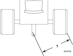
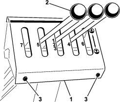
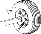
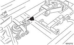
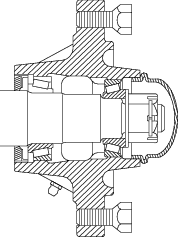
Replacing the Wheel Bearings
-
Jack up the wheel being serviced. Support with jack stand to prevent it from falling.
-
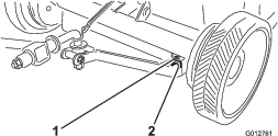
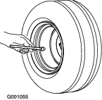
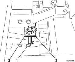
Remove the hub cap, cotter key, slotted nut, and washer (Figure 35).
-
Pull off the wheel and outer bearing cone. Remove the inner bearing cone and seal from the hub. A slot in the hub is provided so the cone and seal can be removed with the bearing cup. Drive against bearing cup.
-
Clean the hub with a solvent.
-
Press the new cups in the hub, being certain they are fully seated.
-
Pack the new cones with wheel bearing grease. Coat bearing journal and adjacent bearings in hub.
-
Grease the sealing lip and slip the new seal on the extended race of the inner bearing cone.
-
Reassemble in reverse order of disassembly.
-
Tighten the slotted nut until the bearings bind slightly when rotating the wheel by hand. Back off the slotted nut to the nearest cotter pin hole and secure with a new cotter pin.
-
Reinstall the hub caps.
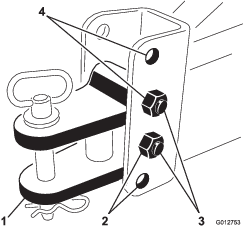
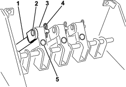
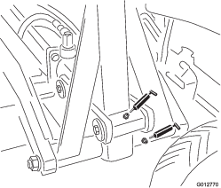
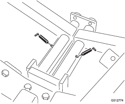
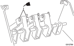
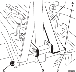
Replacing the Lift-Arm Bushing
-
Position lift arm in the down position.
-
Remove the cutting unit.
-
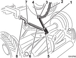
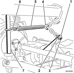
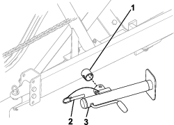
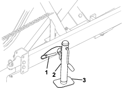
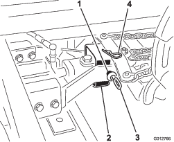
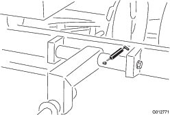
Remove the nut from the end of the pin (Figure 36).
-
Remove the capscrew from the pin assembly.
-
Remove the link between the hydraulic cylinder and the lift arm.
-
Remove the pin assembly.
-
Remove the bushings in the lift arm.
-
Insert and size the new bushings and replace the pin.
-
Replace the capscrew and nut.
-
Install the link.
-
Grease the bushing with Mobilux #2 grease or equivalent.
Important: It may be necessary to drive the pin assembly out of the lift arm. Be careful not to damage the threads.