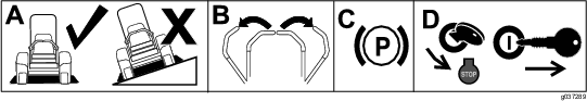
Note: Determine the left and right sides of the machine from the normal operating position.
Installation
Preparing the Machine
-
Park the machine on a level surface.
-
Move the motion-control levers to the NEUTRAL-LOCK position.
-
Engage the parking brake.
-
Shut off the engine and remove the key.
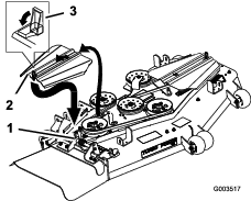
Removing the Existing Belt Cover and Bracket
Note: Clean the area around the belt cover before removing it.
-
Lower the mower deck to the lowest height-of-cut position.
-
Unlatch and remove the right belt cover (Figure 2).
Retain the hardware.
-
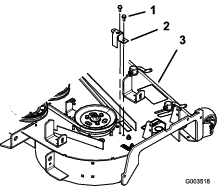
Remove the outside right belt cover bracket (Figure 3).
-
Store the right belt cover, bracket, and hardware for later use if you remove the bagger blower and pulley.
-
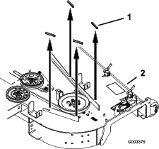
For 72-inch mower decks only—remove the 4 rubber stops from the mower deck (Figure 4).
Installing the Pulley Assembly and Belt
Parts needed for this procedure:
| Pulley assembly | 1 |
| Pulley-plate mount—for machines with an aluminum spindle only | 1 |
| Flange nut (3/8 inch)—for machines with an aluminum spindle only | 3 |
For Machines with an Aluminum Spindle
-
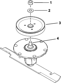
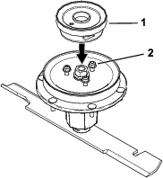
Remove the top nut, washer, and sheave from the spindle (Figure 5).
Note: Note the orientation of the sheave when you remove it from the spindle to ensure that you install it properly later in the process.
-
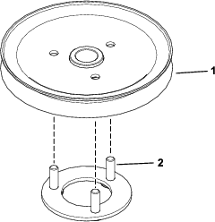
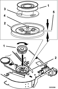
Insert the pulley-plate mount studs into the holes in the sheave (Figure 6).
-
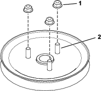
Loosely install the 3 nuts to the studs (Figure 7).
Leave a clearance of 5 mm (3/16 inch) between the nut and sheave.
-
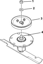
Install the sheave assembly to the spindle using the washer and top nut (Figure 8).
-
Torque the top nut to 176 to 217 N∙m (130 to 160 ft-lb).
Note: Ensure that the sheave spins freely.
-
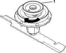
Align the new pulley assembly so that the openings fit over the nuts (Figure 9).
-
Turn the pulley to lock it into position (Figure 10).
Note: If the pulley does not turn, loosen the nuts more to raise the nuts and allow the pulley to lock into position.
-
After the new pulley assembly is in position, tighten the nuts to secure new pulley assembly.
Torque the 3 nuts to 28 to 34 N∙m (21 to 25 ft-lb).
-
Install the deck belt.
For Machines with Bolts
-
Loosen, but do not remove, the tapping bolts on the existing mower-deck pulley (Figure 11).
Note: There should be a 5 mm (3/16 inch) clearance between the bolt head and pulley.
-
Align the new pulley assembly so that the openings fit over the pulley bolt heads (Figure 11).
-
Turn the pulley to lock it into position (Figure 11).
Note: If the pulley does not turn, loosen the bolts more to raise the bolt heads and allow the pulley to lock into position.
-
After the new pulley assembly is in position, tighten the existing bolts to secure new pulley assembly.
Note: Torque the bolts to 28 to 34 N∙m (21 to 25 ft-lb).
-
Install the deck belt.
Removing the Existing Anti-Scalp Roller and Bracket
Note: Do not perform this procedure if a pivot is installed.
-
Clean the area around the right, rear anti-scalp roller.
-
Remove the anti-scalp roller from the bracket by loosening and removing the flange nut (3/8 inch) and axle bolt (3/8 x 4-1/2 inches) as shown in Figure 12.
Save all hardware for later use.
-
Remove the 3 carriage bolts (3/8 x 3/4 inch) and 3 flange nuts (3/8 inch) securing the bracket to the mower (Figure 12).
Save all hardware for later use.
Installing the Blower Pivot
Parts needed for this procedure:
| Blower pivot | 1 |
| Metal template | 1 |
| Bolt (3/8 x 1 inch) | 3 |
| Locknut (3/8 inch) | 3 |
Note: Do not perform this procedure if a pivot is installed.
-
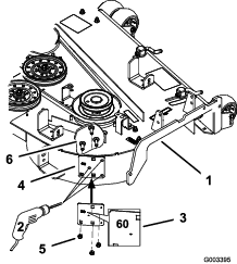
Install the metal template with the number 60 in it to the mower deck with the previously removed carriage bolts and nuts using the existing holes in the mower deck (Figure 13).
Ensure that the carriage bolts and nuts are tight and the template is tight against the mower deck.
-
Center-punch the new mower deck hole locations using the 3 holes in the template (Figure 13).
-
Remove the metal template and drill 3 pilot holes (1/8-inch diameter) with a sharp drill bit (Figure 13).
-
Drill 3 holes (13/32-inch diameter) into the pilot holes with a sharp drill bit (Figure 13).
-
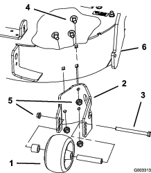
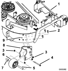
Install the new blower pivot using 3 bolts (3/8 x 1 inch) and 3 locknuts (3/8 inch) using the drilled holes (Figure 14).
-
Install the anti-scalp roller to the blower pivot using the previously removed axle bolt (3/8 x 4-1/2 inches), spacer, bushing, and flange nut (3/8 inch) as shown in Figure 14.
Installing the Blower Pivot
Parts needed for this procedure:
| Blower pivot | 1 |
| Metal template | 1 |
| Bolt (3/8 x 1 inch) | 4 |
| Locknut (3/8 inch) | 4 |
Note: Do not perform this procedure if a pivot is installed.
-
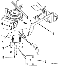
Install the metal template with the number 72 in it to the mower deck with the previously removed carriage bolts and nuts using the existing holes in the mower deck (Figure 15).
Ensure that the carriage bolts and nuts are tight and the template is tight against the mower deck.
-
Center-punch the new mower deck hole locations using the 4 holes in the template (Figure 15).
-
Remove the metal template and drill 4 pilot holes (1/8-inch diameter) with a sharp drill bit (Figure 15).
-
Drill 4 pilot holes (13/32-inch diameter) into the pilot holes with a sharp drill bit (Figure 15).
-
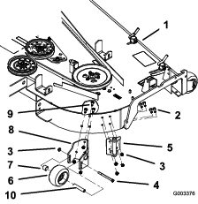
Install the new blower pivot using 4 bolts (3/8 x 1 inch) and 4 locknuts (3/8 inch) using the drilled holes (Figure 16).
-
Install the anti-scalp roller bracket using the previously removed carriage bolts and nuts to the mower deck (Figure 16).
-
Install the anti-scalp roller to the bracket using the previously removed axle bolt (3/8 x 4-1/2 inches), bushings, and flange nut (3/8 inch) as shown in Figure 16.
Installing the Blower Assembly, Bagger Belt, Spring and Blower-Belt Cover
Parts needed for this procedure:
| Blower assembly | 1 |
| Bagger belt | 1 |
| Blower belt cover | 1 |
| Spring | 1 |
Refer to the bagger Operator's Manual for the correct procedure to install the blower, bagger belt, spring, and blower-belt cover.