Installation
Note: Determine the left and right sides of the machine from the normal operating position.
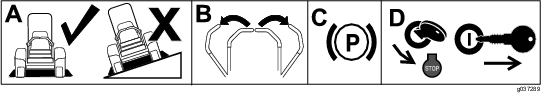
Preparing the Machine
-
Park the machine on a level surface.
-
Move the motion-control levers to the NEUTRAL-LOCK position.
-
Engage the parking brake.
-
Shut off the engine and remove the key.
Removing the Existing Belt Cover, Belt, and Bracket
Installing the Pulley Assembly and Belt
Parts needed for this procedure:
| Pulley assembly | 1 |
-
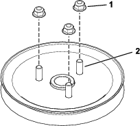
Remove the flange nuts from the existing mower deck pulley (Figure 4).
-
Align the new pulley assembly so that the openings fit over the pulley studs (Figure 5).
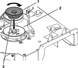
-
Turn the pulley to lock it into position and install the flange nuts (Figure 6).
-
After the new pulley assembly is in position, tighten the flange nuts to secure new pulley assembly.
-
Torque the nuts to 28 to 34 N∙m (21 to 25 ft-lb).
-
Install the deck belt.
Installing the Pulley Assembly and Belt
Parts needed for this procedure:
| Pulley assembly | 1 |
| Pulley-plate mount | 1 |
| Flange nut (3/8 inch) | 3 |
-
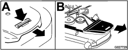
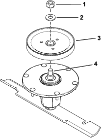
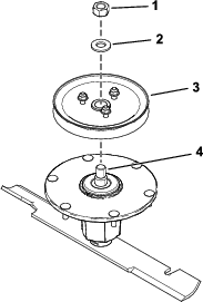
Remove the top nut, washer, and sheave from the spindle (Figure 7).
Note: Note the orientation of the sheave when you remove it from the spindle to ensure that you install it properly later in the process.
-
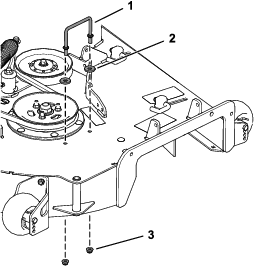
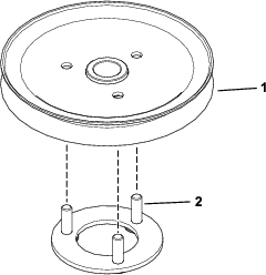
Insert the pulley-plate mount studs into the holes in the sheave (Figure 8).
-
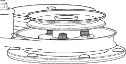
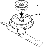
Loosely install the 3 nuts to the studs (Figure 9).
Leave a clearance of 5 mm (3/16 inch) between the nut and sheave.
-
Install the sheave assembly to the spindle using the washer and top nut (Figure 10).
-
Torque the top nut to 176 to 217 N∙m (130 to 160 ft-lb).
Note: Ensure that the sheave spins freely.
-
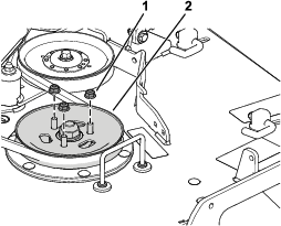
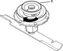
Align the new pulley assembly so that the openings fit over the nuts (Figure 11).
-
Turn the pulley to lock it into position (Figure 12).
Note: If the pulley does not turn, loosen the nuts more to raise the nuts and allow the pulley to lock into position.
-
After the new pulley assembly is in position, tighten the nuts to secure new pulley assembly.
Torque the 3 nuts to 28 to 34 N∙m (21 to 25 ft-lb).
-
Install the deck belt.
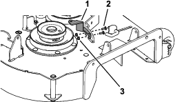
Installing the New Belt-Cover Bracket
Parts needed for this procedure:
| Belt-cover bracket | 1 |
| Carriage bolt (1/4 x 3/4 inch) | 2 |
| Locknut (1/4 inch) | 2 |
Install the belt-cover bracket using the 2 carriage bolts (1/4 x 3/4 inch) and 2 locknuts (1/4 inch) as shown in Figure 13.
Installing the Blower Assembly, Bagger Belt, Spring and Blower-Belt Cover
Parts needed for this procedure:
| Blower assembly | 1 |
| Bagger belt | 1 |
| Blower belt cover | 1 |
| Spring | 1 |
| Knob | 1 |
Refer to the bagger Operator's Manual for the correct procedure to install the blower, bagger belt, spring, and blower belt cover.