Safety
Safety and Instructional Decals
 |
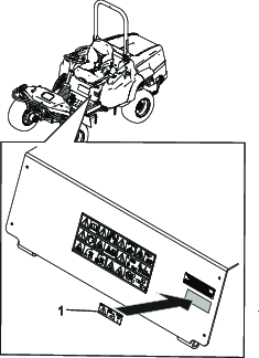
Safety decals and instructions are easily visible to the operator and are located near any area of potential danger. Replace any decal that is damaged or missing. |
Installation
Determine the left and right sides of the machine from the normal operating position.
Preparing the Machine
-
Park the machine on a level surface.
-
Disengage the power takeoff and lower the attachments.
-
Engage the parking brake.
-
Shut off the engine and remove the key.
-
Wait for all movement to stop.
-
Allow machine components to cool.
Updating the Machine Software
Update the machine software to the latest version in ToroDiag.
Note: This ensures the software is updated for calibration and use of the slope sensor.
Installing the Kit
Parts needed for this procedure:
| Sensor module | 1 |
| Bolt (1/2 x 1 inch) | 2 |
| Nut (1/4 inch) | 2 |
| Bolt (1/4 x 1-1/4 inch) | 2 |
| Mounting bracket | 1 |
| Wire harness | 1 |
| Alarm | 1 |
| Cable tie | 4 |
Installing the Sensor Module
-
Disconnect the battery. Refer to the Operator’s Manual for the procedure.
-
Move the seat forward.
-
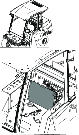
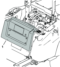
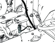
Tilt the back cover forward or remove to gain access to the wires (Figure 1 or Figure 2).
-
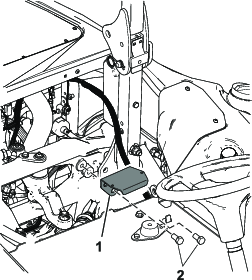
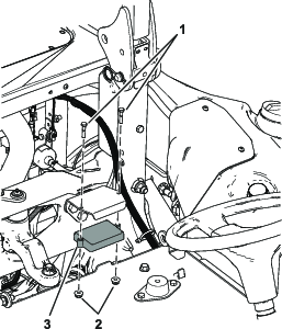
Install the sensor bracket to the frame with 2 bolts (1/2 x 1 inch); refer to Figure 3.
Note: The holes in the frame are threaded.
-
Install the sensor to the sensor bracket with 2 bolts (1/4 x 1-1/4 inch) and 2 nuts (1/4 inch); refer to Figure 4.
-
Plug the 90° connector into the sensor (Figure 5 and Figure 8).
-
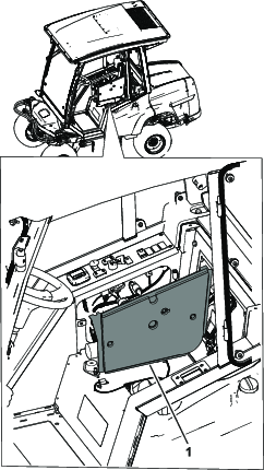
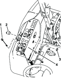
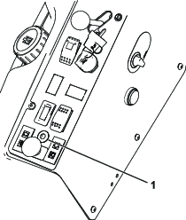
Remove the control panel on the console or loosen and raise up the control panel (Figure 6 or Figure 7).
-
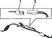
Remove the knockout for the alarm.
-
Install the alarm (Figure 7).
Note: Installing the light and removing the decal area is for machines without an InfoCenter only.
-
Remove the area in the console decal for the light.
-
Install the light from the top of the console (Figure 7).
Routing the Wire Harness
-
Route the wire harness under the seat pan and along the along the existing wire harness in the cross channel (Figure 8).
-
Route the wire harness to the controls.
-
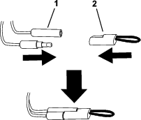
Install the middle connector to the machine wire harness connector labled TELEMATICS port or EXPANSION port (Figure 8).
-
Connect the wire harness to the light and the alarm (Figure 8).
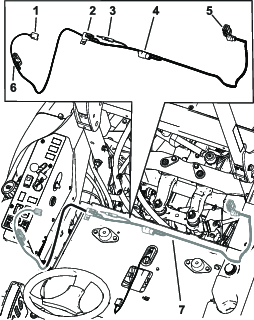
-
Secure the harness away from any hot or moving parts with cable ties.
-
Install the control panel to the console for machines with a cab or install the control panel for machines with a rollbar (Figure 6 or Figure 7).
-
Connect the battery. Refer to the Operator’s Manual for the procedure.
Calibrating the Sensor
-
While on a flat surface, remove the plug from the calibration connectors (Figure 9).
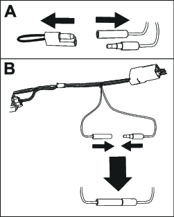
-
Plug the calibration connectors together as shown in Figure 9.
-
Turn the ignition key to the ON position, but do not start the engine.
-
Use the following processes depending what your machine has installed.
-
Infocenter display:
-
The InfoCenter shows advisory 195, Slope Sensor Calibrating.
Note: The LED light at the top of the display screen (Figure 10) blinks as the sensor calibrates.
-
When the InfoCenter shows advisory 196, Slope Sensor Calibrated, the light no longer blinks, and the alarm beeps once, turn the ignition key to the OFF position.
-
-
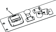
Console light:
-
The LED light (Figure 11) blinks as the sensor calibrates.
-
When the LED light turns off and the alarm beeps once, the sensor is calibrated.
-
Turn the ignition key to the OFF position.
-
-
-
Disconnect the calibration connectors and install the plug onto the connectors (Figure 12).
Installing the Decal
Operation
Use the following procedures depending what your machine has installed.
Warning
Slopes are a major factor related to loss-of-control and tip-over accidents, which can result in severe injury or death.
Use extreme caution when operating the machine on a slope.
Using the Slope Sensor with an InfoCenter
The light and alarm indicates the severity of the slope (Figure 10):
-
No light—normal operating conditions
-
Slow, flashing red light and Advisory 196 displaying on the screen—moderate slope

-
Fast, flashing red light, audible alarm, and Advisory 197 displaying on the screen—steep slope; proceed to a more shallow slope.

Using the Slope Sensor with the LED Light
The light and alarm indicates the severity of the slope(Figure 11):
-
No light—normal operating conditions
-
Slow, flashing red light—moderate slope
-
Fast, flashing red light and audible alarm—steep slope; proceed to a more shallow slope.