Safety
Autosteer Safety
The GeoLink Autosteer system provides steering guidance control, when the proper conditions are met, but you are responsible for driving the machine and must remain alert and in complete control of the machine at all times.
When using the control console for assisted steering during spraying operation, ensure that you operate the machine with attention to the following:
-
The control console does not detect obstacles or hazards, keep the machine away from people, animals, buildings, and other structures.
-
Do not operate the machine near high-voltage power lines or other overhead obstacles.
-
Ensure that the operating area is clear of obstacles.
-
Know the position of the machine and the ground (field) conditions at all times.
-
Respond if the satellite signal or the RTK correction signal is lost momentarily.
Note: When fallback mode is enabled, the system remains engaged if the RTK correction is lost and momentarily drops to float, estimated, or GPS. The system only disengages if the GPS signal is lost.
Take manual control of the machine if an obstacle appears in the path of the machine or if the machine moves off of the guideline.
Product Overview
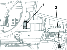
Enable/Transport Switch
Use the Autosteer enable/transport switch to enable the steering assist (Spray Mode) function or put the machine in transport mode.
Engage/Disengage Switch
Use the Autosteer engage/disengage switch to engage or disengage the steering assist function.
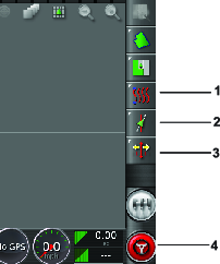
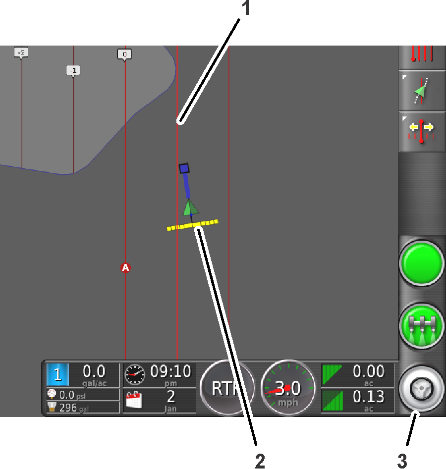
Figure 1 shows the engage/disengage switch displayed in the control console.
Operation
Understanding the Icons
The color of the icon changes with the state of the system.
| Icon color | Auto Steer State | Description |
|---|---|---|
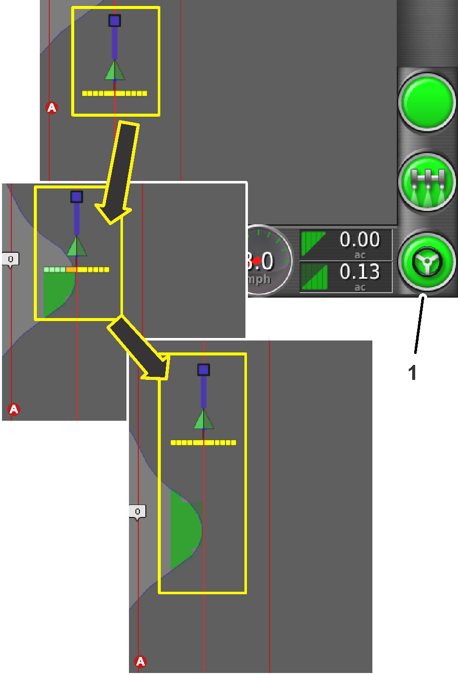
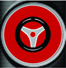 | Not engaged | Autosteer is not engaged and not active. Push the Autosteer steering wheel icon (Figure 1) to see the condition(s) preventing the system from engaging. |
| Red | ||
 | Standby | The steering assist function is ready to use. |
| White | ||
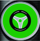 | Engaged | Autosteer is engaged and active. Select the Autosteer steering wheel icon to return to manual steering mode. Note: The icon may briefly flash blue before turning green. |
| Green |
Understanding the Alarms
Visual alarms
-
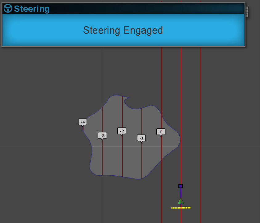
STEERING ENGAGED—a visual alarm displays when the steering assist function engages (Figure 3).
-
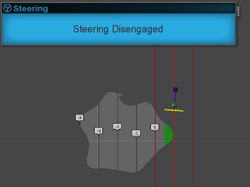
STEERING DISENGAGED—a visual alarm displays when the steering assist function disengages (Figure 4). The system may disengage because of the following causes:
-
Weak satellite signal.
-
The GPS system loses the guideline or a degradation of the RTK connection.
-
You manually turn the steering wheel.
-
Audible alarm
The audible alarm sounds when you disengage or engage the steering assist function.
Understanding the Steering Options Menu
Using the Status Screen
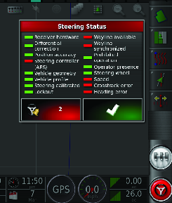
The status screen displays the conditions required for operating the machine with Autosteer.
-
The conditions marked with a green indicator are ready for operation.
-
The conditions marked with a red indicator show that the steering assist function is not ready for operation.
-
Navigate to the guidance toolbar and press the Autosteer icon (Figure 5).
-
Review the status of each condition in the list. Perform 1 of the following:
-
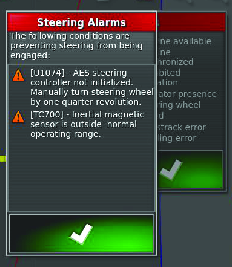
Press the Steering Alarm Icon at the bottom left of the screen to display the list of steering alarms.
-
Press the Steering Alarm information icon, the red button next to the confirm icon, to see detailed information regarding the steering alarms.
-
Press the Confirm icon to return to the main screen.
Important: Before using the steering assist function, complete the conditions with red indicators, working through the conditions from top to bottom in the status screen.
Steering Status Table
Condition Description when the condition displays in red: Receiver hardware Check that the receiver is connected and getting electrical power. Differential corrections The control console may not match the correction source requirements. Position accuracy The satellite receiver needs time for signal convergence. Check the number and color of the satellite icons on the control console. Drive the machine to a clearing with no overhead power lines. Steering controller Check that the controller is connected and getting electrical power. Vehicle geometry The vehicle geometry is incorrect. Select a new vehicle profile. Vehicle profile Check which vehicle is selected in the controller and check the geometry settings. Steering calibrated The steering needs to be calibrated; refer to your Toro Distributor or Toro’s NSN Service Center. Lockout The steering system is in transport mode. Guideline (wayline) available The machine is too far from the guideline—drive closer to the guideline. Check that the guideline is created and selected. Guideline (wayline) synchronized The guideline is not loaded. Check that the satellite receiver has a satellite signal and the receiver loads the guideline. It may take time to upload guidelines to a satellite receiver, particularly for large curved guidelines. Prohibited operation The system cannot engage when certain actions are performed, such as steering calibration, changing GPS settings, or exporting a job. Operator presence Sit in the operator’s seat. Steering wheel Loosely hold the steering wheel when engaging the steering assist function. Speed Drive the machine between 1 to 12.9 kph (0.7 to 8 mph). The required speed may vary by machine. Crosstrack error Drive the machine closer to the guideline before engaging the steering assist function. Heading error Check the angle or vehicle speed that the machine is traveling when approaching a guideline. Check the compass calibration. -
Creating Guidelines
| Guideline Icon | Description |
|---|---|
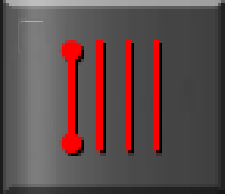 | AB Line Guidance |
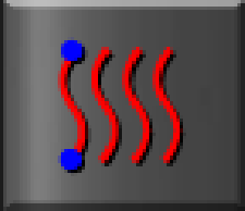 | Identical Curve Guidance |
 | Guidelock Guidance |
 | Boundary Curve Guidance |
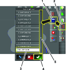
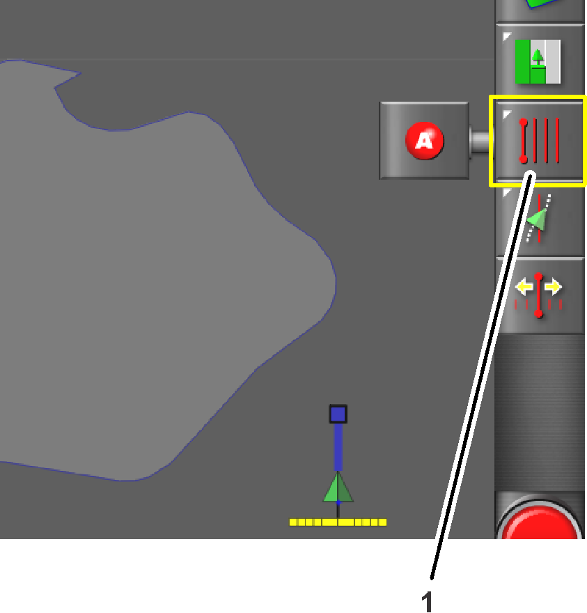
Displaying Programmed Guidelines
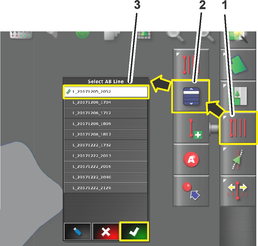
-
Press the guideline menu icon (Figure 7).
Note: If needed, change between the AB guideline or the curved guideline.
-
Press the select guideline menu (Figure 7).
Then select the AB line menu or the select curve menu appears.
-
For longer lists of guidelines, swipe the scroll bar to navigate the full list of guidelines (Figure 7).
-
Press the AB line icon for the guideline that is created for your job (Figure 7).
-
Press the Confirm icon (Figure 7).
The control console displays the field with the selected guidelines.
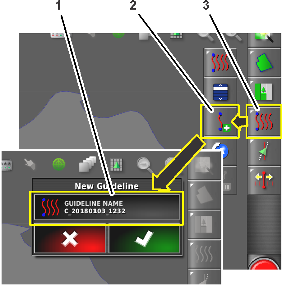
Creating a Guideline Entry

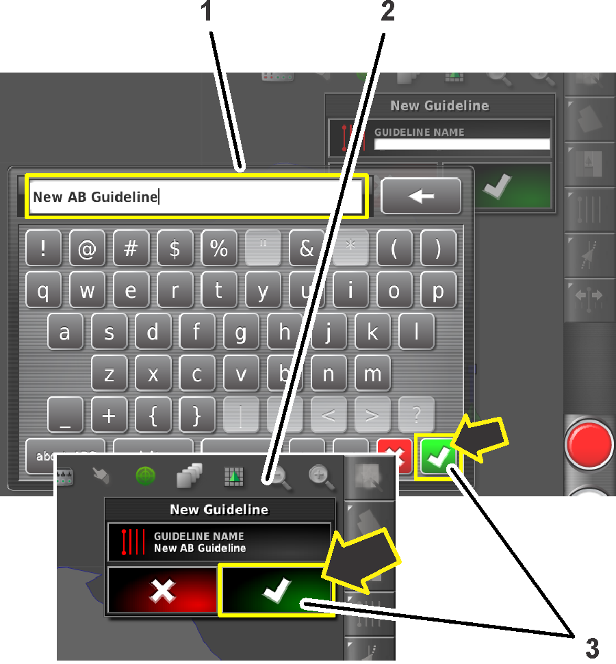
Creating a Straight Guideline
To create a guideline start by defining the starting point (point A) and the end point (point B). This AB line is used to establish the parallel guidelines to cover the whole field or a boundary.
-
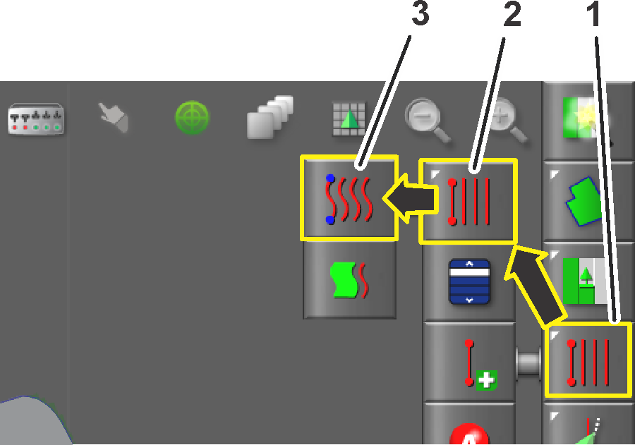
Switch the guideline type to an AB (straight) guideline (Figure 10).
-
Create a new guideline entry in the select guideline menu, refer to Creating a Guideline Entry.
-
Drive the machine to the starting point of a guideline.
-
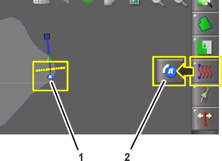
Press the guideline menu icon (Figure 11).
-
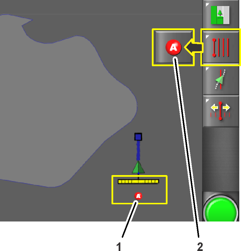
Press the set point A icon (Figure 12).
-
Drive the machine to the other side of the field boundary to the location where you want the AB guideline to reference (Figure 13).
-
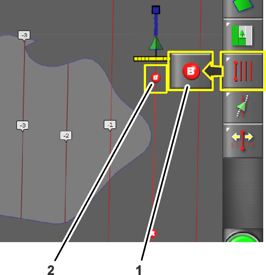
Press the set point B icon (Figure 13).
The AB guidelines appear in the control console.
-
The machine will drive straight at the end of a guide line.
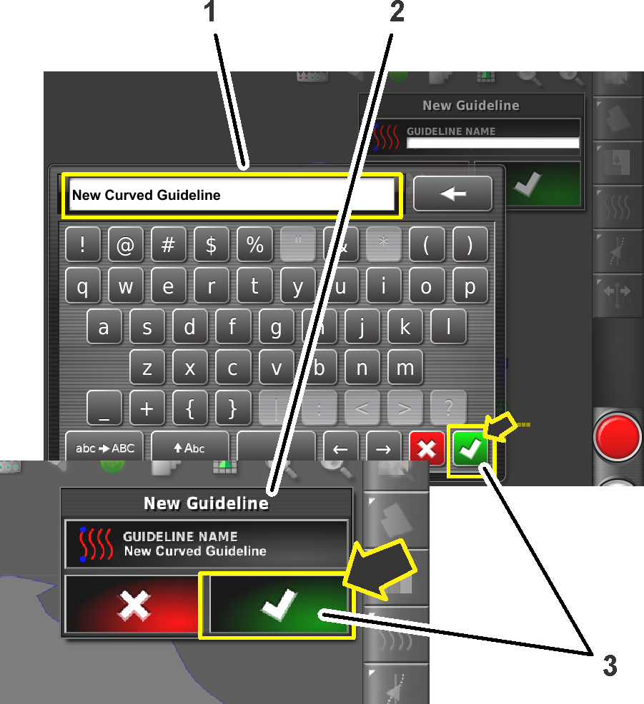
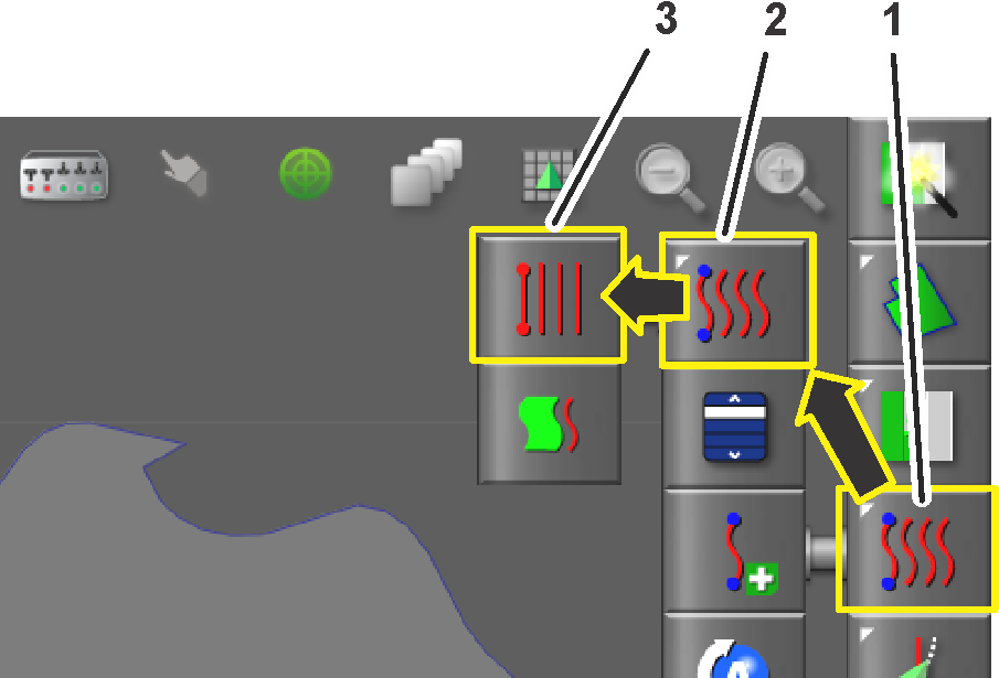
Creating a Curve Guideline
-
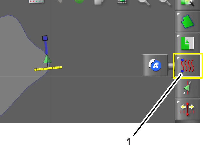
Switch the guideline type to a curve guideline (Figure 14).
-
Create a new guideline entry in the select guideline menu, refer to Creating a Guideline Entry.
-
Drive the machine to the starting point of a guideline.
-
Press the guideline menu icon (Figure 15).
-
Press the Set Point A icon (Figure 16).
Point B will display in the control console.
-
Drive the machine along the contour path of the field boundary (Figure 17).
The control console displays the path with a red line.
Note: Press the pause/resume recording icon to temporarily stop and start the recording of the path.
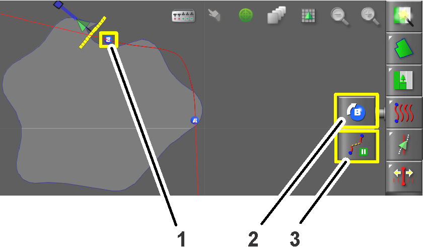
-
Press the Set Point B icon (Figure 17).
Point A will display in the control console.
-
The machine will drive straight at the end of a guide line.
Nudging the Guideline Position
Use the nudge icon creates a new guideline identical to the created guideline in a new location.
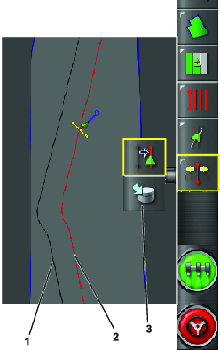
-
Drive to the area where you want to create the nudged guideline. You will see red lines showing you where the nudged guideline will be placed.
-
Push the nudge icon when you are in the location where you want the new guideline (Figure 18).
-
Press the Save Nudged Guideline icon to store the new guideline in the control console.
Driving the Machine with Autosteer
Selecting a Guideline
Note: Refer to Creating Guidelines when a new guideline is needed.
-
Press the guideline menu icon (Figure 19).
-
Press the select guideline icon (Figure 19).
-
Press the icon for the type of guideline you need.
-
For straight or curved guidelines, press the select guidance icon (Figure 19) for an AB or the curved guideline.
A Select menu displays a list of programmed guidelines.
-
Press the desired guideline name box and press the confirm icon (Figure 19).
Using Autosteer to Drive the Machine
-
Confirm that all steering status items, except for the speed status, are OK (colored green); refer to Using the Status Screen.
-
Zoom and pan the control console until the machine icon is sized and centered in the screen.
-
Set the enable/transport switch of the machine to the SPRAY position.
-
Drive the machine to the desired starting point of the active boundary that you intend to spray.
-
Confirm that the Autosteer icon in the lower right corner of the control console is colored white (standby)
 .
.Note: If the steering icon is red, correct the condition not met from the status screen (Figure 5).
-
Press the Autosteer icon in the lower, right corner of the control console (Figure 22) or press the engage/disengage switch of the machine (Figure 20).
The Autosteer icon turns green and the machine steers toward the nearest guideline.
Important: The system is tuned to provide smooth engagement and transitions while operating; if you believe your system engages or transitions too abuptly, stop using the auto guidance function and contact NSN support.
-
When the machine drives outside the boundary, disengage the auto guidance function by performing 1 of the following actions:
-
Select the Autosteer icon at the lower right corner of the control console.
-
Rotate the steering wheel left or right.
-
Press the Autosteer engage/disengage switch on the machine.
-
Stop the machine.
-
-
Align the machine for the next spraying pass with the next guideline displayed in the control console.