Note: Install this kit to use with the E-Z Vac Twin Bagger; refer to the Operator’s Manual for the bagger for safety, operation, and maintenance procedures.
Important: For Grandstand machines with the serial ranges listed below, engage the clutch at least 50 times before installing and operating the Blower and Drive Kit.• Model 74513—Serial number 405291650 and before• Model 79518—Serial number 405291708 and before• All other models—Serial number 405453838 and beforeEnsure to engage the clutch at least 45 seconds and disengage it at least 15 seconds each time. This can be accomplished through normal use of the machine before installing the kit.
Warning
CALIFORNIA
Proposition 65 Warning
Use of this product may cause exposure to chemicals known to the State of California to cause cancer, birth defects, or other reproductive harm.
Safety
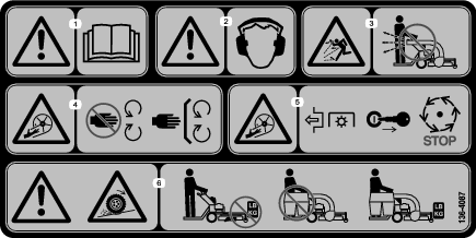
Safety and Instructional Decals
 |
Safety decals and instructions are easily visible to the operator and are located near any area of potential danger. Replace any decal that is damaged or missing. |

Installation
Note: Determine the left and right sides of the machine from the normal operating position.
Preparing the Machine
Perform the following procedure to prepare the machine for attaching the blower and finishing kit.
-
Disengage the PTO, move the motion-control levers to the NEUTRAL-LOCK position, and engage the parking brake.
-
Shut off the engine, remove the key, and wait for all moving parts to stop before leaving the operating position.
-
Repair all bent or damaged areas of mower deck and replace any missing parts.
-
Clean the machine of any debris on the deck or rear part of the machine to ease installation.
Removing the Discharge Chute and Existing Belt Cover
Note: Retain all parts and install them on the machine whenever you remove the bagger.
Installing the Pulley and Idler Assemblies
Parts needed for this procedure:
| Blower mount | 1 |
| Bolt (1/2 x 1-1/2 inches) | 1 |
| Lock washer | 1 |
| Nut (1/2 inch) | 1 |
| Bolt (3/8 x 1-1/4 inches) | 1 |
| Nut (3/8 inch) | 1 |
| Carriage bolt (3/8 x 1-1/4 inches) | 1 |
| Carriage bolt (3/8 x 1 inch) | 1 |
| Idler assembly | 1 |
| Pulley assembly | 1 |
-
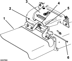
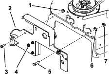
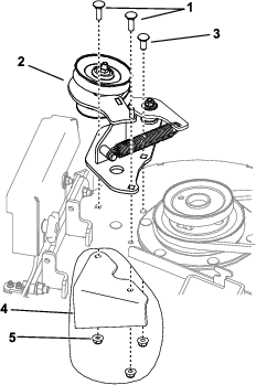
Install the blower mount to the deck using 1 bolt (1/2 x 1-1/2 inches), 1 lock washer, 1 nut (1/2 inch), 1 bolt (3/8 x 1-1/4 inches), and 1 nut (3/8 inch) as shown in Figure 3.
Note: You may need to loosen the 3 baffle bolts when you install the blower mount to align the assembly with the deck. Tighten the bolts after installing the mount.
-
Remove the nuts from the spindle in the right deck pulley and use them to attach the pulley assembly to the deck pulley (Figure 4).
Note: You may need to remove the mower belt to relieve the tension off the deck pulley when you install the pulley assembly. Refer to the Operator’s Manual for the machine.
-
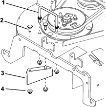
Using the 3 nuts that you removed previously, 1 carriage bolt (3/8 x 1-1/4 inches), and 2 carriage bolts (3/8 x 1 inch), install the idler assembly to the mower deck (Figure 5).
Installing the Pulley Assembly and Belt
Parts needed for this procedure:
| Pulley assembly | 1 |
| Bolt (1/2 x 1-1/2 inches) | 1 |
| Lock washer | 1 |
| Nut (1/2 inch) | 1 |
| Bolt (3/8 x 1-1/4 inches) | 1 |
| Nut (3/8 inch) | 1 |
| Carriage bolt (3/8 x 1-1/4 inches) | 1 |
| Carriage bolt (3/8 x 1 inch) | 1 |
| Pulley-plate mount | 1 |
| Flange nut (3/8 inch) | 3 |
-
Install the blower mount to the deck using 1 bolt (1/2 x 1-1/2 inches), 1 lock washer, 1 nut (1/2 inch), 1 bolt (3/8 x 1-1/4 inches), and 1 nut (3/8 inch) as shown in Figure 3.
Note: You may need to loosen the 3 baffle bolts when you install the blower mount to align the assembly with the deck. Tighten the bolts after installing the mount.
-
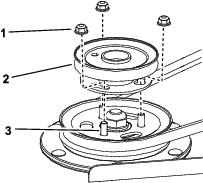
Remove the top nut, washer, and sheave from the spindle (Figure 6).
Note: Note the orientation of the sheave when you remove it from the spindle to ensure that you install it properly later in the process.
-
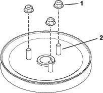
Insert the pulley-plate mount studs into the holes in the sheave (Figure 7).
-
Loosely install the 3 nuts to the studs (Figure 8).
Leave a clearance of 5 mm (3/16 inch) between the nut and sheave.
-
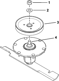
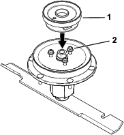
Install the sheave assembly to the spindle using the washer and top nut (Figure 9).
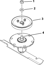
-
Torque the top nut to 176 to 217 N∙m (130 to 160 ft-lb).
Note: Ensure that the sheave spins freely.
-
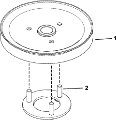
Align the new pulley assembly so that the openings fit over the nuts (Figure 10).
-
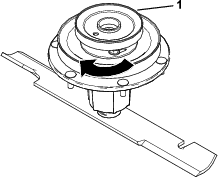
Turn the pulley to lock it into position (Figure 11).
Note: If the pulley does not turn, loosen the nuts more to raise the nuts and allow the pulley to lock into position.
-
After the new pulley assembly is in position, tighten the nuts to secure new pulley assembly.
Torque the 3 nuts to 28 to 34 N∙m (21 to 25 ft-lb).
-
Using the 3 nuts that you removed previously, 1 carriage bolt (3/8 x 1-1/4 inches), and 2 carriage bolts (3/8 x 1 inch), install the idler assembly to the mower deck (Figure 5).
-
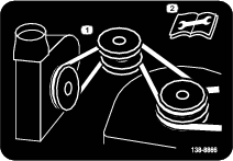
Install the deck belt.
Installing the Blower Assembly, Belt, and Belt Cover
Parts needed for this procedure:
| Blower assembly | 1 |
| Belt | 1 |
| Belt cover | 1 |
| Knob | 1 |
| Hose | 1 |
| Hose clamp | 1 |
Refer to the bagger Operator’s Manual for the correct procedure to install the blower assembly, belt, and belt covers.