| Maintenance Service Interval | Maintenance Procedure |
|---|---|
| Before each use or daily |
|
Introduction
This stand-on spreader sprayer is intended for use by trained operators in residential and commercial applications. The machine is primarily designed for chemical distribution used for turf care or snow/ice removal at residential grounds, parks, sports fields, and on commercial grounds. Using this product for purposes other than its intended use could prove dangerous to you and bystanders.
Read this information carefully to learn how to operate and maintain your product properly and to avoid injury and product damage. You are responsible for operating the product properly and safely.
Visit www.Toro.com for product safety and operation training materials, accessory information, help finding a dealer, or to register your product.
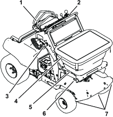
Whenever you need service, genuine Toro parts, or additional information, contact an Authorized Service Dealer or Toro Customer Service and have the model and serial numbers of your product ready. Figure 1 identifies the location of the model and serial numbers on the product. Write the numbers in the space provided.
Important: With your mobile device, you can scan the QR code (if equipped) on the serial number plate to access warranty, parts, and other product information.
It is a violation of California Public Resource Code Section 4442 or 4443 to use or operate the engine on any forest-covered, brush-covered, or grass-covered land unless the engine is equipped with a spark arrester, as defined in Section 4442, maintained in effective working order or the engine is constructed, equipped, and maintained for the prevention of fire.
The enclosed engine owner's manual is supplied for information regarding the US Environmental Protection Agency (EPA) and the California Emission Control Regulation of emission systems, maintenance, and warranty. Replacements may be ordered through the engine manufacturer.
Warning
CALIFORNIA
Proposition 65 Warning
The engine exhaust from this product contains chemicals known to the State of California to cause cancer, birth defects, or other reproductive harm.
Battery posts, terminals, and related accessories contain lead and lead compounds, chemicals known to the State of California to cause cancer and reproductive harm. Wash hands after handling.
Use of this product may cause exposure to chemicals known to the State of California to cause cancer, birth defects, or other reproductive harm.
Safety
The following instructions are from ANSI standard B71.4-2017.
Safety-Alert Symbol
The safety-alert symbol (Figure 2) is used both in this manual and on the machine to identify important safety messages that you must follow to avoid an accident.
This symbol means Attention! Become Alert! Your Safety Is Involved!

The safety-alert symbol appears above information which alerts you to unsafe actions or situations and is followed by the word Danger, Warning, or Caution.
Danger indicates an imminently hazardous situation which, if not avoided, will result in death or serious injury.
Warning indicates a potentially hazardous situation which, if not avoided, could result in death or serious injury.
Caution indicates a potentially hazardous situation which, if not avoided, may result in minor or moderate injury.
This manual uses 2 other words to highlight information. Important calls attention to special mechanical information and Note emphasizes general information worthy of special attention.
General Safety
This machine is capable of amputating hands and feet and of throwing objects. Toro designed and tested this machine to offer reasonably safe service; however, failure to comply with safety instructions may result in injury or death.
-
Read, understand, and follow all instructions and warnings in the Operator’s Manual and other training materials, on the machine, the engine, and attachments. All operators and mechanics should be trained. If the operator(s) or mechanic(s) cannot read this manual, it is the owner’s responsibility to explain this material to them; other languages may be available on our website.
-
Only allow trained, responsible, and physically capable operators who are familiar with the safe operation, operator controls, and safety signs and instructions to operate the machine. Never allow children or untrained people operate or service the equipment. Local regulations may restrict the age of the operator.
-
Always use appropriate personal protective equipment (PPE) to guard against contact with chemicals.
-
Do not operate the machine near drop-offs, ditches, embankments, water, or other hazards.
-
Do not put your hands or feet near moving components of the machine.
-
Never operate the machine with damaged guards, shields, or covers. Always have safety shields, guards, switches and other devices in place and in proper working condition.
-
Stop the machine, shut off the engine, and remove the key before servicing, fueling, or unclogging the machine.
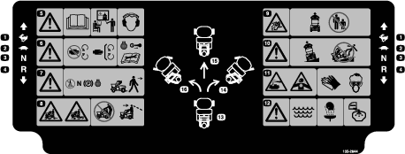
Safety and Instructional Decals
-
Keep all safety signs legible. Remove all grease, dirt, and debris from safety signs and instructional labels.
-
Replace all worn, damaged, or missing safety signs.
-
When you install replacement components, ensure that current safety signs are affixed to those components.
-
If you have installed an attachment or accessory, ensure that current safety signs are visible.
-
Familiarize yourself with the following safety signs and instruction labels. They are critical to the safe operation of your machine.


Setup
Checking the Tire Air Pressure
Check the air pressure in the front and rear tires, and if necessary, add air to the appropriate pressure; refer to Checking the Air Pressure in the Tires.
Checking the Engine-Oil Level
The engine comes with oil; check the engine-oil level and, if necessary, add to the appropriate level; refer to Engine Oil Specification and Checking the Engine-Oil Level.
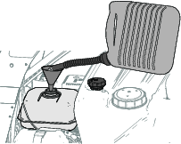
Checking the Transaxle-Fluid Level
The transaxle comes with fluid; check transaxle-fluid level in the expansion tank, and if necessary, add to the appropriate level; refer to Servicing the Transaxle.
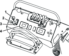
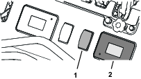
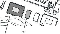
Connecting the Battery
-
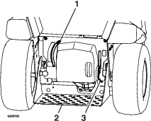
Remove the battery cover from the battery box (Figure 3).
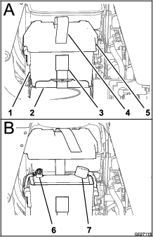
-
Install the positive battery cable to the positive (+) battery terminal with a flanged bolt and flanged nut (Figure 3).
-
Install the negative battery cable to the negative (–) battery terminal with a flanged bolt and flanged nut (Figure 3).
-
Install the cover on the battery box and secure the cover and box to the battery tray with the battery strap (Figure 3).
Product Overview
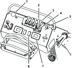
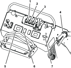
Machine Controls
Steering Control
The steering control is located behind the control console (see Figure 6).
-
Move the steering control to the right or left to steer the machine to the right or left respectively.
-
Moving the steering control to the center allows the machine to steer straight.
Motion-Control Lever
The motion-control lever, located in the center of the steering control, controls the forward and reverse motion of the machine (see Figure 6).
-
Move the motion-control lever forward or backward to drive the machine respectively.
Note: The machine speed is proportional to the amount that you move the motion-control lever.
-
When you move the motion-control lever to the center position, the machine should stop.
Note: When you release the motion-control lever, it should return to the NEUTRAL position.
Important: If the motion-control lever does not return to the NEUTRAL position when you release it, contact an Authorized Service Dealer.
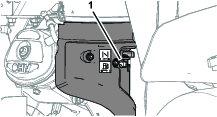
Parking-Brake Lever
The parking-brake lever is located above the platform on the right side (Figure 7).
-
To engage the parking brake, push the parking-brake lever down.
Note: The brake lever engages a parking brake in the transaxle.
-
To release the parking brake, pull the lever up.
Note: When parking on a steep slope, chock or block the wheels in addition to engaging the parking brake. When transporting the machine, engage the parking brake and bind the machine to the transport vehicle.
Drive-Wheel-Release Lever
The drive-wheel-release lever is located above the platform on the left side (Figure 7).
Use the drive-wheel-release lever to disengage the hydrostatic-drive system to move the machine by hand.
-
To push or pull the machine, move the drive-wheel-release lever up.
-
To operate the machine, move the drive-wheel-release lever down.
Engine Controls
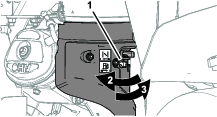
Ignition Switch
The ignition switch is located at the left side of the control console (Figure 8).
Use the ignition switch to start and run, or shut off the engine. The ignition switch has 3 positions: STOP, RUN and START.
Note: You must engage the parking brake to start the engine.
Choke Control
The choke control is located at the left side of the control console; you use it to help start a cold engine (Figure 8).
Note: Do not start or run a warm engine with the choke in the ON position.
-
Pull up on the choke control to set the choke to the ON position.
-
Push down on the choke control to set the choke to the OFF position.
Throttle Control
The throttle control (the red lever) is located at the left side of the control console (Figure 8).
Hour Meter (Sprayer and Information Display)
The hour meter displays in the sprayer and information display is located to the right of the throttle, at the bottom of the control console (Figure 8).
The hour meter records the number of hours that the machine has operated. Hour meter time displays when the key is in the run position and the sprayer control switch is shut off.
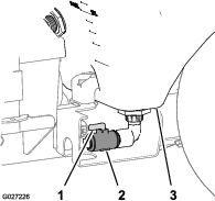
Fuel-Shutoff Valve
The fuel-shutoff valve is located at the front, right side of the engine below the fuel tank (Figure 9).
Note: Close the fuel-shutoff valve when you do not use the machine for a few days, transport the machine to and from the job site, or park the machine inside a building.
Spreader Controls
Deflector Gate Control
The deflector-gate control is located to the above the throttle on the control console (Figure 10).
Use the deflector-gate control to temporarily stop the discharge of granular materials at the left side of the spreader. Close the deflector gate with the control when it is not desirable to broadcast granular materials onto sidewalks, parking lots, or patios.
-
Push the knob for the deflector-gate control down to close the gate and temporarily deflect the granular materials.
-
Pull the knob up to open the deflector gate for full granular broadcasting.
Heavy Distribution Granular-Gate Lever
The heavy distribution granular-gate lever is the fourth lever located at the top center of the control console (Figure 10).
-
To broadcast a wide pattern of granular material, pull the heavy distribution granular-gate lever rearward to the full open position.
-
To close the impeller gate, push the heavy distribution granular-gate lever forward full closed position.
Light Distribution Granular-Gate Lever
The light distribution granular-gate lever is the fifth lever located at the top center of the control console (Figure 10).
-
To broadcast a narrow pattern of granular material, pull the light distribution granular-gate lever rearward fully to the limited OPEN position.
-
To close the impeller gate, push the heavy distribution granular-gate lever forward fully.
Note: Only the heavy distribution granular-gate lever closes the impeller gate. Pushing the heavy distribution granular-gate lever forward also resets the light distribution granular-gate lever to the forward position.
Spreader-Pattern Control
The spreader-pattern control is located to the right of the deflector-gate control at the control console (Figure 10).
Use the spreader-pattern control to broadcast a heavier pattern of granular material to the left or right side of the machine.
-
To broadcast a heavier pattern to the left, unlock the spreader-pattern control, pull the control up slightly, and lock the control.
-
To broadcast a heavier pattern to the right, unlock the spreader-pattern control, push the control down slightly, and lock the control.
Flow-Rate Adjustment Knob—light Distribution Granular Gate
The flow-rate adjustment knob is located below the heavy distribution- and light distribution impeller-gate levers (Figure 10).
Use the flow-rate adjustment knob to control the discharge rate of granular material from the hopper onto the impeller when the light distribution granular-gate lever is in the OPEN position (limited).
-
Rotate the narrow-spreader distribution-flow-rate knob clockwise to decrease the discharge rate of granular material from the hopper.
-
Rotate the distribution flow-rate-knob counterclockwise to increase the discharge rate of granular material from the hopper.
Impeller Control Switch
The impeller control switch is located to the left of the Impeller-speed display, at the bottom of the control console (Figure 10).
Use the impeller control switch to run the electric motor that drives the impeller.
Spreader and Information Display
The spreader and information display is located below the distribution impeller-gate levers at the bottom of the control console (Figure 10).
The spreader and information display shows the following information:
-
The spreader controller firmware version
-
An hour meter for the spreader-impeller motor
-
The speed of the impeller motor as a percent of motor-rotation speed
-
Fault codes
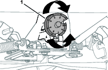
Drop-rate Cam and Linkage
The drop-rate cam and linkage are located at the front of the machine and below the hopper on the spreader (Figure 11).
Use the drop-rate cam to set the maximum amount of material to be dispensed through the impeller gate and onto the impeller.
The slot in the cam, after setting 9 on the cam, allows you to open the impeller gate to the maximum position. You can use this setting for dry sand, ice melt, or other materials that are difficult to spread.
Note: Use cam setting 9 may when you are cleaning out the hopper.
Sprayer Controls
Tank-Agitation Lever
The tank-agitation lever is located on the control console (Figure 12).
Setting the tank-agitation lever to the ON position allows the sprayer pump to circulate the content in the spray tank to keep the chemical solution mixed.
-
Pull the tank-agitation lever to circulate the content in the spray tank.
-
Push the lever to stop circulating the content in the spray tank.
Note: Do not use agitation while spraying. Shut off the tank agitation to ensure proper spray distribution.
Note: Run the engine speed above idle and run the sprayer pump for the tank agitation to work effectively.
Narrow-Spray Pattern Lever
The narrow-spray pattern lever is located on the control console (Figure 12).
-
To turn ON the sprayer in a narrow-spray pattern (the center nozzle only), pull the narrow-spray pattern lever toward you.
-
To turn OFF the sprayer, push the narrow-spray pattern lever away from you.
Wide-Spray Pattern Lever
The wide-spray pattern lever is located on the control console (Figure 12).
-
To turn ON the sprayer in a wide-spray pattern (the right and left nozzles), pull the wide-spray pattern lever toward you.
-
To turn OFF the sprayer, push the wide-spray pattern lever away from you.
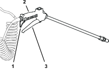
Spray-Wand Trigger and Trigger Lock
The spray-wand trigger and trigger lock are located on the bottom of the spray-wand handle (Figure 12 and Figure 13).
-
To use the spray wand, hold the handle of the wand squeeze the trigger.
-
To lock the trigger to the ON position, fully squeeze the trigger against the handle and then latch the trigger lock over the trigger; to unlock the trigger, unlatch the trigger lock from the trigger.
-
Release the trigger to stop the spray.
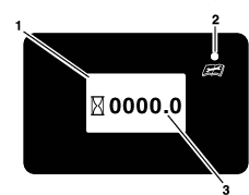
Sprayer and Information Display
The sprayer and information display is located to the right of the throttle, at the bottom of the control console (Figure 12).
The sprayer and information display shows the following information:
-
Sprayer controller firmware version
-
Hour meter for the engine
-
Hour meter for the sprayer-pump motor
-
Battery voltage
-
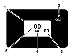
Spray-system pressure
-
Fault codes
Sprayer-Pump Switch
The sprayer-pump switch is located to the left of the hour meter and spray pressure display, on the control console (Figure 12).
Use the sprayer-pump switch to start the electric motor that drives the sprayer pump and recirculation pump, adjust the sprayer system pressure, and shut off sprayer pump and recirculation pump motors.
Spray-Wand Pressure Control
The spray-wand pressure control is located to the right of the impeller-speed display, at the right side of the control console (Figure 12).
Use the spray-wand pressure control the spray-system pressure at the spray wand.
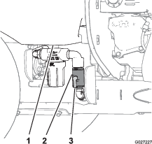
Tank Drain Valve
The tank drain valve is located at the left side and under the sprayer tank (Figure 15).
Use the tank drain valve to empty the sprayer tank of liquid chemicals.
-
To open the valve, rotate the handle of the tank drain valve 90° clockwise (lever in-line with valve).
-
To close the valve, rotate the handle 90° counterclockwise.
Sprayer-Pump-Supply Valve
The sprayer-pump-supply valve is located at the right side of the machine and under the sprayer tank (Figure 15).
Use the sprayer-pump-supply valve to shut off the flow of liquid chemicals to the pump.
-
To open the valve, rotate the handle valve 90° clockwise (lever in-line with valve).
-
To close the valve, rotate the handle 90° counterclockwise.
| Overall width | 90 cm (35.5 inches) | |
| Overall length | 171 cm (67.5 inches) | |
| Overall height | 131 cm (51.5 inches) | |
| Weight | sprayer tank and hopper empty | 227 kg (500 lb) |
| only hopper full | 307 kg (676 lb) | |
| only sprayer tank full | 309 kg (682 lb) | |
| sprayer tank and hopper empty and 1 extra bag of granular material in the tank | 412 kg (909 lb) | |
| Maximum machine weight | loaded machine + operator | ≤ 513 kg (1130 lb) |
| Hopper capacity | 79 kg (175 lb) | |
| Spreader Cast | 1.2 m (4 ft) through 6.7 (22 ft) | |
| Sprayer tank capacity | 76 L (20 US gallon) | |
| Maximum Spray Width | Narrow pattern | 1.5 m (5 ft) |
| Wide pattern | 3.4 m (11 ft) | |
| Maximum ground speed | forward | 9 kph (5.5 mph) |
Operation
Note: Determine the left and right sides of the machine from the normal operating position.
Before Operation
Before Operation Safety
General Safety
-
Evaluate the terrain to determine what accessories and attachments are needed to properly and safely perform the job. Use only accessories and attachments approved by Toro.
-
Inspect the area where you will use the equipment, and remove all rocks, toys, sticks, wires, bones, and other foreign objects that may be contaminated by chemicals and/or affect the stability of the machine.
-
Wear appropriate clothing, including safety glasses, substantial slip-resistant footwear, and hearing protection. Tie back long hair and avoid loose clothing or jewelry that may get tangled in moving parts.
-
Do not operate the machine while people, especially children, or pets are in the area. Stop the machine and the attachment(s) if anyone enters the area.
-
Do not fill, calibrate, or clean the machine while people, especially children, or pets are in the area.
-
Check all sprayer components for wear and leaks before applying pressure to the system. Do not use the machine if it is leaking or damaged.
-
Ensure that the operator platform is clean and free from chemical residue and debris buildup.
-
Check that the operator-presence controls, safety switches, and shields are attached and functioning properly. Do not operate the machine unless they are functioning properly. Frequently check for worn or deteriorating components and replace them with the manufacturer’s recommended parts when necessary.
Chemical Safety
Chemical substances used in the spreader-sprayer system may be hazardous and toxic to you, bystanders, animals, plants, soils or other property.
-
Carefully read and follow the chemical warning labels and Safety Data Sheets (SDS) for all chemicals used and protect yourself according to the chemical manufacturer's recommendations. Ensure that as little skin as possible is exposed while using chemicals. Use appropriate personal protective equipment (PPE) to guard against personal contact with chemicals, such as the following:
– safety glasses, goggles, and/or face shield
– chemical-resistant gloves
– rubber boots or other substantial footwear
– hearing protection
– respirator or filter mask
– clean change of clothes, soap, and disposable towels, to be kept on-hand in the event of a chemical spill
-
If you are using more than 1 chemical, read the information about each chemical. Refuse to operate or work on the spreader-sprayer if this information is not available.
-
Before working on a spreader-sprayer system, ensure that the system has been triple rinsed and neutralized according to the recommendations of the chemical manufacturer(s) and that all the valves have been cycled three times.
-
Verify there is an adequate supply of clean water and soap nearby, and immediately wash off any chemicals that contact you.
-
Obtain proper training before using or handling chemicals.
-
Use the correct chemical for the job.
-
Follow the chemical manufacturer's instructions for the safe application of the chemical and do not exceed the recommended system application pressure.
-
Handle chemicals in a well-ventilated area.
-
Have clean water available, especially when filling the spray tank.
-
Do not eat, drink, or smoke while working with chemicals.
-
Do not clean spray nozzles by blowing through them or placing them in your mouth.
-
Always wash your hands and other exposed areas as soon as possible after finishing the work.
-
Keep chemicals in their original packages and in a safe location.
-
Properly dispose of unused chemicals and chemical containers as instructed by the chemical manufacturer and your local codes.
-
Chemicals and fumes are dangerous; never enter the tank or hopper, and do not place your head over or in the opening.
-
Follow all local, state, and federal requirements for spreading and spraying chemicals.
Fuel Safety
Use extreme care when handling fuel.
In certain conditions gasoline is extremely flammable and its vapors are explosive. A fire or explosion from gasoline can burn you, others, and cause property damage.
-
Fill the fuel tank outdoors on level ground, in an open area, when the engine is cold. Wipe up any gasoline that spills.
-
Never refill the fuel tank or drain the machine indoors or inside an enclosed trailer.
-
Do not fill the fuel tank completely full. Fill the fuel tank to the bottom of the filler neck. The empty space in the tank allows the gasoline to expand.
-
Never smoke when handling gasoline, and stay away from an open flame or where gasoline fumes may be ignited by a spark.
-
Store gasoline in an approved container and keep it out of the reach of children.
-
Add fuel before starting the engine. Never remove the cap of the fuel tank or add fuel when engine is running or when the engine is hot.
-
If you spill fuel, do not attempt to start the engine. Move away from the area of the spill and avoid creating any source of ignition until the fuel vapors have dissipated.
-
Do not operate the machine without the entire exhaust system in place and in proper working condition.
-
In certain conditions during fueling, static electricity can be released, causing a spark, which can ignite gasoline vapors. A fire or explosion from gasoline can burn you and others and cause property damage.
-
Always place gasoline containers on the ground away from your vehicle before filling.
-
Do not fill gasoline containers inside a vehicle or on a truck or trailer bed, because interior carpets or plastic truck bed liners may insulate the container and slow the loss of any static charge.
-
When practical, remove gasoline-powered equipment from the truck or trailer and refuel the equipment with its wheels on the ground.
-
If this is not possible, then refuel such equipment on a truck or trailer from a portable container rather than from a gasoline-dispenser nozzle.
-
If you must use a gasoline-dispenser nozzle, keep the nozzle in contact with the rim of the fuel tank or container opening at all times until fueling is complete. Do not use a nozzle lock-open device.
-
-
Gasoline is harmful or fatal if swallowed. Long-term exposure to vapors has caused cancer in laboratory animals. Failure to use caution may cause serious injury or illness.
-
Avoid prolonged breathing of vapors.
-
Keep your face away from the nozzle and gasoline tank or container opening.
-
Keep gasoline away from your eyes and skin.
-
Never siphon gasoline by mouth.
-
-
To help prevent fires, do the following:
-
Keep the engine and the engine area free from accumulation of grass, leaves, excessive grease or oil, and other debris that can accumulate in these areas.
-
Clean up oil and fuel spills and remove fuel-soaked debris.
-
Allow the machine to cool before storing the machine in any enclosure. Do not store the machine near a flame or any enclosed area where open pilot lights or heat appliances are present.
-
Performing Daily Maintenance
Before starting the machine each day, perform the following daily-check procedures:
Checking the Safety Interlock System
Caution
If interlock switch is disconnected or damaged the machine could operate unexpectedly causing personal injury.
-
Do not tamper with the interlock switch.
-
Check the operation of the interlock switch daily and replace damaged switch before operating the machine.
Important: Ensure that the safety mechanisms on your machine are connected and in proper operating condition prior to operating your machine.
The safety interlock system is designed to prevent the engine from starting unless you engage the parking brake.
Testing the Starter Interlock
| Maintenance Service Interval | Maintenance Procedure |
|---|---|
| Before each use or daily |
|
-
Move the machine to a level surface.
-
Chock the wheels of the machine.
-
Disconnect the spark-plug wires.
-
Release the parking brake.
-
With the motion-control lever in the NEUTRAL position turn the key to the START position.
Note: The starter must not rotate the engine.
-
If the starter rotates the engine of your machine—the machine does not pass this test, do not operate it. Contact your authorized Toro distributor.
-
If the starter does not rotate the engine—the machine does pass the test: engage the parking brake, connect the spark-plug wire to the spark plug, and remove the chock(s) from the wheels.
-
Fuel Specification
| Petroleum fuel | Use unleaded gasoline with an octane rating of 87 or higher ((R+M)/2 rating method). |
| Ethanol blended fuel | Use an unleaded-gasoline blend with up to 10% ethanol (gasohol) or 15% MTBE (methyl tertiary butyl ether) by volume is acceptable. Ethanol and MTBE are not the same. |
| Gasoline with 15% ethanol (E15) by volume is not approved for use. Never use gasoline that contains more than 10% ethanol by volume, such as E15 (contains 15% ethanol), E20 (contains 20% ethanol), or E85 (contains up to 85% ethanol). Using unapproved gasoline may cause performance problems and/or engine damage which may not be covered under warranty. |
Important: For best results, use only clean, fresh fuel (less than 30 days old).
-
Do not use gasoline containing methanol.
-
Do not store fuel either in the fuel tank or fuel containers over the winter unless you use a fuel stabilizer.
-
Do not add oil to gasoline.
Using Stabilizer/Conditioner
Use a fuel stabilizer/conditioner in the machine to provide the following benefits:
Important: Do not use fuel additives containing methanol or ethanol.
Add the correct amount of fuel stabilizer/conditioner to the gasoline.
Note: A fuel stabilizer/conditioner is most effective when mixed with fresh gasoline. To minimize the chance of varnish deposits in the fuel system, always use fuel stabilizer.
Filling the Fuel Tank
Fuel tank capacity: 6.8 L (1.8 US gallons)
Note: Refueling the engine is difficult when using a larger refueling container such as a container with a 19 L (5 US gal) capacity.To make fueling the machine easier, use a 4 to 8 L (1 to 2 US gal) fuel container and a funnel.
-
Park the machine on a level surface and shut off the engine.
-
Allow the engine to cool.
-
Clean around the fuel-tank cap and remove it (Figure 16).
-
Fill the tank with fuel (Figure 16) to within 6 to 13 mm (1/4 to 1/2 inch) from the top of the tank. Do not fill into the filler neck of the tank.
Important: Do not fill the tank more than 6 mm (1/4 inch) from the top of the tank because the fuel needs room to expand.
-
Install the fuel-tank cap securely.
-
Wipe up any spilled fuel.
During Operation
During Operation Safety
General Safety
Use your full attention when operating the machine. Do not engage in any activity that causes distractions; otherwise, injury or property damage may occur.
-
Running the engine will cause engine parts, especially the muffler, to become extremely hot. Severe burns can occur on contact, and debris, such as leaves, grass, and brush, can catch fire.
-
Allow engine parts, especially the muffler, to cool before touching them.
-
Remove accumulated debris from the muffler and engine area.
-
-
Engine exhaust contains carbon monoxide, which is an odorless, deadly poison that can kill you. Do not run the engine indoors or in a small, confined area where carbon monoxide fumes can collect.
-
Chemicals are hazardous and can cause personal injury.
-
Read the directions on the chemical labels before handling the chemicals and follow all manufacturer recommendations and precautions.
-
Keep chemicals away from your skin. Should contact occur, wash the affected area thoroughly with soap and clean water.
-
Wear goggles, gloves, and any other protective equipment recommended by the chemical manufacturer.
-
The owner/user can prevent and is responsible for accidents that may cause personal injury or property damage.
-
This machine was designed for 1 operator only. Do not carry passengers and keep all others away from machine during operation.
-
Do not operate the machine under the influence of alcohol or drugs.
-
Operate only in daylight or good artificial light.
-
Do not operate the machine when there is the risk of lightning.
-
Be aware of weather conditions and check that spray nozzles, patterns, and volume are suitable.
-
Keep away from holes, ruts, bumps, rocks, and other hidden hazards. Use care when approaching blind corners, shrubs, trees, tall grass or other objects that may hide obstacles or obscure vision. Uneven terrain could overturn the machine or cause you to lose your balance or footing.
-
Do not operate the machine with damaged guards, shields, or covers. Always have safety shields, guards, switches and other devices in place and working properly.
-
Keep clear of the discharge area at all times.
-
Keep your hands and feet away from moving parts. If possible, Do not make any adjustments while engine is running.
-
-
Your hands, feet, hair, clothing, or accessories can become entangled in rotating parts and cause serious injury.
-
Do not operate the machine without guards, shields, and safety devices in place and working properly.
-
Keep your hands, feet, hair, jewelry, or clothing away from rotating parts.
-
-
Be aware of the spreading/spraying path and direct the discharge away from others. Avoid discharging material against a wall or obstruction as the material may ricochet back toward you.
-
Be alert, slow down, and use caution when making turns. Look behind you and to the side before changing directions. Do not spread or spray in reverse unless it is absolutely necessary.
-
Stop spreading or spraying while making tight turns to minimize uneven distribution pattern, application rate, and chemical drift.
-
Chemicals may drift and cause injury to people and animals; it may also damage plants, soil, or other property.
-
Do not change the engine governor setting or overspeed the engine.
-
Ensure that all drives are in neutral and engage the parking brake before starting the engine.
-
Park the machine on level ground. Shut off the engine, wait for all moving parts to stop, remove key, and engage the parking brake before doing the following:
-
Checking, cleaning, or working on the machine
-
Clearing blockages
-
Leaving the machine; do not leave a running machine unattended.
-
-
Shut off the engine, wait for all moving parts to stop, and engage parking brake before refueling.
-
Tragic accidents can occur if you are not alert to the presence of children. Children are often attracted to the machine and the spreader-spraying activity. Never assume that children will remain where you last saw them.
-
Keep children out of the working area and under the watchful care of another responsible adult.
-
Be alert and shut off the machine if children enter the area.
-
Before and while backing or changing direction, look behind you, down, and side-to-side for small children.
-
Never allow children to operate the machine.
-
Do not carry children, even if the machine is not in use. Children could fall off and be seriously injured or interfere with the safe operation of the machine. Children wanting a ride could appear in the working area without warning and be run over or backed over by the machine.
-
-
Reduce the weight of the load when operating the machine on hills and rough terrain to avoid tipping or overturning of the machine.
-
Liquid loads and granular materials can shift. This shifting happens most often while turning; going up or down hills; suddenly changing speeds; or while driving over rough surfaces. Shifting loads can cause the machine to tip over.
-
When operating with a heavy load, reduce your speed and allow for sufficient stopping distance.
-
Reduce the speed and load while operating the machine on rough terrain, uneven ground, and near curbs, holes, and other sudden changes in terrain. Loads may shift, causing the sprayer to become unstable.
-
Sudden changes in terrain may cause abrupt steering wheel movement, possibly resulting in hand and arm injuries. Reduce the speed when operating on rough terrain or near curbs.
-
Safely relieve liquid from the spray wand every time you shut off the engine.
-
The spray wand traps liquids under high pressure, even when engine is not running. High-pressure spray discharge could cause serious injury or death.
-
Keep clear of the nozzle and do not direct spray or stream at people, pets, or non-work area property.
-
Do not direct the spray on or near electrical power components or source.
-
Do not repair the spray wand, hoses, seals, nozzle, or other wand components; replace them.
-
Do not attach hoses or other components to the end of the spray wand nozzle.
-
Do not attempt to disconnect the spray wand from the machine while the system is pressurized.
-
Do not use the spray wand if the trigger lock is damaged or missing.
-
Do not keep the spray wand in the locked-open position after you complete the job.
-
When draining or relieving the system, Do not allow anyone to stand in front of the nozzles and do not drain on a person’s feet.
-
Slope Safety
Slopes are a major factor related to loss of control and rollover accidents, which can result in severe injury or death. You are responsible for safe slope operation. Operating the machine on any slope requires extra caution.
-
Review the slope instructions listed below for operating the machine on slopes and to determine whether you can operate the machine in the conditions on that day and at that job site. Changes in the terrain can result in a change in slope operation for the machine.
-
Operate across slopes, never up and down. Avoid operation on excessively steep or wet slopes.
-
Identify hazards at the base of the slope. Determine if the slope is safe for machine operation, including surveying the site. Always use common sense and good judgment when performing this survey.
-
Avoid starting, stopping, or turning the machine on slopes. Travel up and down on slopes. Avoid making sudden changes in speed or direction. If you must turn the machine, turn it slowly and gradually downhill, if possible. Use care when reversing the machine.
-
Do not operate a machine when you are uncertain about the traction, steering, or stability.
-
Remove or mark obstructions such as ditches, holes, ruts, bumps, rocks, or other hidden hazards. Tall grass can hide obstructions. Uneven terrain could overturn the machine.
-
Be aware that operating the machine on wet surfaces, across slopes, or downhill may cause the machine to lose traction. Loss of traction to the wheels may result in sliding and a loss of braking and steering.
-
Use extreme caution when operating the machine near drop-offs, ditches, embankments, water hazards, or other hazards. The machine could suddenly roll over if a wheel goes over the edge or the edge caves in. Establish a safety area between the machine and any hazard.
-
Use extra care while operating the machine with attachments; they can affect the stability of the machine.
-
If the engine stalls or you begin to lose momentum while climbing a hill, gradually apply the brakes and slowly back straight down the hill.
-
Always keep the transmission in gear (if applicable) when you drive the machine down a slope.
-
Do not park the machine on an incline.
-
The weight of the material in the tank can change the handling of the machine. To avoid loss of control and personal injury, follow these guidelines:
-
When operating with a heavy load, reduce your speed and allow for sufficient braking distance. Do not suddenly apply the brakes. Use extra caution on slopes.
-
Liquid loads shift, especially while turning, going up or down slopes, suddenly changing speeds, or while driving over rough surfaces. Shifting loads can cause the machine to tip over.
-
Operating the Machine
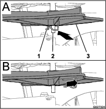
Extending and Retracting the Operator’s Platform
Extending the Operator’s Platform
-
Pull the platform-lock knob inward until the pin of clears the upper hole in the chassis (Figure 18).
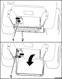
-
Rotate the operator’s platform down until the pin of the platform lock aligns with the lower hole in the chassis (Figure 18).
-
Move the platform-lock knob outward until the pin protrudes through the lower hole (Figure 18).
Retracting the Operator’s Platform
-
Pull the platform-lock knob inward until the pin clears the upper hole in the chassis (Figure 18).
-
Rotate the operator’s platform up until the pin of the platform lock aligns with the upper hole in the chassis (Figure 18).
-
Move the platform-lock knob outward until the pin protrudes through the upper hole (Figure 18).
Opening and Closing the Fuel Shutoff Valve
Control fuel flow to the engine with the fuel shutoff valve as follows:
-
To open the fuel-shutoff valve, fully rotate the handle for the valve left.
-
To close the fuel-shutoff valve, fully rotate the handle of the valve right.
Starting the Engine
Caution
The machine produces sound levels in excess of 85 dBA at the operator’s ear, and may cause hearing loss through extended periods of exposure.
Wear hearing protection while operating the machine.
-
Ensure that the fuel-shutoff valve is open; refer to Opening and Closing the Fuel Shutoff Valve.
-
Move the steering-control/motion-control lever in NEUTRAL position and engage the parking brake; refer to Steering Control, Motion-Control Lever, and Parking-Brake Lever.
Note: To start the engine, you must engage the parking brake. (You can start the engine while you are off the platform.)
-
Move the throttle lever midway between the SLOW and FAST positions; refer to Throttle Control.
-
If the engine is cold, pull up the choke control to the ON position; refer to Choke Control.
Note: If the engine is warm , push down the choke lever to the OFF position.
-
Rotate the ignition switch to the START position; refer to Ignition Switch.
Note: When the engine starts, release the switch.
Important: Do not crank the engine continuously for more than 10 seconds at a time. If the engine does not start, allow a 60 second cool-down period between starting attempts. Failure to follow these guidelines can overheat the starter motor
-
If the choke control is in the ON position, gradually move the lever down, toward the OFF position as the engine warms up.
Shutting Off the Engine
-
Move the steering-control/motion-control lever to the NEUTRAL position and bring the machine to a full stop; refer to Steering Control and Motion-Control Lever.
-
Move the throttle in the midway between the SLOW and FAST positions; refer to Throttle Control.
-
Run the engine for a minimum of 15 seconds, then turn the ignition switch to the OFF position; refer to Ignition Switch.
-
Engage the parking brake; refer to Parking-Brake Lever.
-
Remove the key; refer to Ignition Switch.
-
Close the fuel-shutoff valve when you are not using the machine for a few days, when transporting it, or when it is parked inside a building; refer to Opening and Closing the Fuel Shutoff Valve.
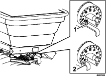
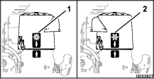
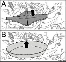
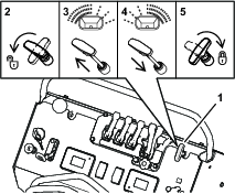
Positioning the Air-Cleaner Cover for Cold or Warm Air Temperature
Important: Running the engine with the air-cleaner cover positioned for cold-weather operation in normal conditions can damage the engine.
The air-cleaner cover has 2 positions: the cold or normal, ambient air positions:
Adjust the air-cleaner cover as follows:
-
When operating in a cold ambient air condition (cold air temperature and humidity), position the air-cleaner cover with snowflake decal facing out (Figure 20).
Note: Use this position during carburetor icing conditions: low outside air temperature with high relative humidity. Symptoms include the engine runs rough at idle or low speed, and it discharges black or white smoke in the exhaust.
-
When operating in a normal ambient air condition, position the air-cleaner cover with sun decal facing out (Figure 20).
Note: Use this position during high outside air temperature with low relative humidity.
Driving the Machine
Caution
The machine can turn rapidly by moving the steering control to the far right or left. You may lose control of the machine, which may injure you and others, and damage the machine.
-
Use caution when making turns.
-
Slow down the machine before making sharp turns.
Important: If the motion-control lever does not return to the NEUTRAL position when you release it, contact an Authorized Service Dealer.
Important: To begin moving the machine (forward or backward), the parking-brake lever must be released (pulled up) before you move the motion-control lever.
Driving the Machine Forward
-
Move the motion-control lever to the NEUTRAL position.
-
Release the parking brake.
-
To drive the machine, perform the following:
-
To move the machine forward in a straight line, center the steering control and move the motion-control lever forward.
Note: The machine moves faster the farther you move the motion-control lever away from the NEUTRAL position.
-
To turn left or right, move the steering control toward the desired turn direction.
-
To stop the machine, move the motion-control lever in the NEUTRAL position.
Note: The stopping distance may vary depending on the spreader-sprayer load.
Note: When you release the motion-control lever, it automatically returns to the NEUTRAL position.
-
Driving the Machine in Reverse
-
Move the motion-control lever to the NEUTRAL position.
-
To move the machine rearward in a straight line, slowly move the motion-control lever rearward.

To turn left or right, move the steering control toward the desired turn direction.
-
To stop the machine, move the motion-control lever to the NEUTRAL position.
Note: Stopping distance may vary depending on the spreader-sprayer load.
Operating the Spreader
Caution
Chemicals are hazardous and can cause personal injury.
-
Read the chemical manufacturer’s directions on the label before handling the chemicals; follow all manufacturer recommendations and precautions.
-
Keep chemicals away from your skin. Should contact occur, wash the affected area thoroughly with soap and clean water.
-
Wear eye protection, gloves, and any other protective equipment recommended by the chemical manufacturer.
Use the spreader to disperses free-flowing granular substances such as grass seed, fertilizer, ice melt, etc. When you use the spreader, first fill the granular hopper, then apply the granular materials to the work site, and finally clean the hopper.
Important: When you use your spreader, thoroughly clean it at the end of the day.
Using the Spreader and Information Display
 Spreader |  Off |
 Motor Overcurrent Error |  Voltage Measurement Error |
 Motor Wire Fault |  Motor Open Error |
 Percent of Full Speed |
Spreader Information Screens
Spreader Start-Up Screens
When the key is switched to the RUN position, the spreader and information display shows the following screens, each for 2 seconds:
Note: The LED status light changes from red, to orange, and to green.


Default Spreader Screen
The default screen appears after the initial start-up screens.

Spreader Motor Screen
The spreader motor screen appears if the impeller control switch is tapped.
Note: If the motor is run for eight seconds, the default screen displays.

Using the Impeller Control Switch
Use the impeller control switch (Figure 27) to start the electric motor that drives the impeller, adjust the impeller-motor speed, and shut off the impeller motor.
-
Tap the top of the impeller control switch to run the impeller motor.
-
Tap the top of the impeller control switch to raise the impeller rotation speed.
-
Tap the bottom of the impeller control switch to lower the impeller rotation speed.
-
Push the bottom of the impeller control switch for 1-second to shut off the impeller motor.
Before Operating the Spreader
Before you start using the spreader, calibrate the spreader for the material that you will disperse; refer to Calibrating the Spreader.
Important: Prior to filling the hopper, verify that you have set the proper spreader-application rate.
Calibrating the Spreader
Calibrate the spreader each time you use a new material. The spreader broadcasts material in a pattern 1.5 to 6.7 m (5 to 22 ft) wide depending on the material particle size, volume/density, rate of travel, and wind conditions.
Use the Spreading Charts along with information from Determining the Distribution Pattern, Determining the Effective Spreading Width, and Calculating the Application Rate when calibrating the spreader.
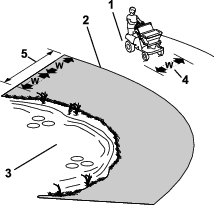
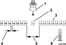
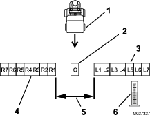
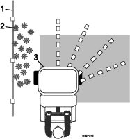
Preparing the Test Site and Machine
Operator supplied equipment: 15 shallow collection pans and 15 graduated measuring cylinders
Note: The most accurate method to measure the distribution uses shallow collection pans and graduated measuring cylinders. In the example below, the 15 shallow collection pans approximately 30 cm (12 inches) wide, 91 cm (36 inches) long, and 5 cm (2 inches) tall.
-
Place one pan in the center of the drive path. Arrange the next two pans, one on each side, far enough apart to allow adequate room for the drive tires of the machine to pass around the center pan.
-
Place the remaining pans in a straight line as shown in Figure 28 or Figure 29.
-
Move the machine far enough away from the test area (where the collection pans are located) to ensure that the machine travels at the desired spreading speed before reaching the site.
-
Determine the application rate and the related drop-rate cam setting; refer to Spreading Charts.
-
Rotate the drop rate cam (Figure 30) to the cam setting you determined in step 4.
-
Fill the hopper approximately half-full with the desired material; refer to Filling the Spreader Hopper.
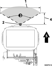
Determining the Distribution Pattern
-
Set the spreader pattern control to the middle of its travel; refer to .
-
Tap the impeller control switch up or down to adjust the broadcasting pattern.
Record the motor-rotation speed here: %.
-
Drive the machine toward the test site at the appropriate speed.
-
As you approach the center pan, pull the wide distribution granular gate control to the open position, and drive over the center pan.
-
Close the gate control, move motion-control lever to the NEUTRAL position, shut off the engine, wait for all moving parts to stop, remove key, and engage parking brake.
-
Label each graduated measuring cylinder to correspond with the distribution pans (such as L2, L1, Center, R1, R2); refer to Figure 28 and Figure 29.
-
One at a time, take a collection pan and dump the contents into the corresponding graduated cylinder. Record the amount of material collected and return the pan to its location. Repeat this until all pan contents have been emptied.
Note: Repeat broadcasting over the test site several times, moving in the same direction each time, until enough material is dispensed to the collection pan to half fill a graduated cylinder.
-
With the graduated measuring cylinder in the same straight line as the pans, evaluate the volume of material in each cylinder to determine the quality of the distribution from the spreader.
-
To adjust the spreader pattern, refer to the Adjusting the Spreader Pattern.
-
Fill the hopper half-full of the desired material and repeat steps 1 through 9 until you achieve a uniform pattern.
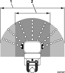
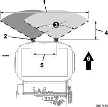
Determining the Effective Spreading Width
Use the effective width to determine the uniform distribution of the material.
Note: The spreading width range is 6 to 8 m (20 to 25 ft).
-
After the spreader pattern is correctly adjusted, evaluate the amount of material in the center graduated measuring cylinder.
-
Locate the 2 graduated cylinder, one each side of center, that contain 1/2 the measured amount of the material that you observed in the center graduated cylinder.
-
Go to the two corresponding pans. Starting from the outer edge, measure the distance between left pan, across the center pan, to the outer edge of the right pan, and record the measurement.
Record the effective spreading width here: .
Preparing the Calibration Course for Calculating the Application Rate
-
Determine a course length by dividing 93 m2 (1,000 ft2) by the effective spread width that you determined in Determining the Effective Spreading Width; use the course length formula. Record the course length here: .
Calibration Course Length Formula
Formula 93 m2 (1,000 ft2) / Effective width measurement = Calibration course length Example 93 m2 (1,000 ft2) / 1.8 m (6 ft) = 51 m (167 ft) Note: In this example the effective width measures 1.8 m (6 ft).
-
Measure and visibly mark the course length. Ensure that you allow enough distance before the starting marker so that the spreader moving forward at full speed when crossing the first mark of the course.
Calculating the Application Rate
-
Determine the area and amount of material that you are applying to the job site and record those amounts in the area and materials worksheet.
Record the job site area here: .
Record the amount of job site material here: .
-
Initially, use the recommended application rate indicated in theSpreading Charts section or use the rate recommended listed on the product manufacturer’s label as a guide to help determine the amount of material that you would spread over a 93 m2 (1,000 ft2) area.
Note: In this example the calibration course is 1.8 m (6 ft) by 51m (167 ft).
-
Set the appropriate drop-rate cam setting; refer to the Spreading Charts as a starting point.
-
Add material to the hopper.
Note: In this example we added 11.3 kg (25 lb) of material.
-
Drive the spreader over the calibration course while applying the material.
-
Empty the remaining material of the hopper into a clean bucket; refer to Emptying the Spreader.
-
Weigh the bucket containing the material and record the weight. Pour the contents back into the hopper and then weigh the empty bucket. Calculate the remaining material weight using the remaining material weight formula. Record the remaining material weight here: .
Remaining Material Weight Formula
Formula (Remaining material and bucket weight) - (Bucket weight) = Remaining material weight Example 10 kg (22 lb) - 1 kg (2 lb) = 9 kg (20 lb) Note: In this example, 9 kg (20 lb) of material remain in the hopper after applying the material to the test course.
-
Calculate applies material weigh using the applied material formula that follows. Record the applied material weight here: .
Applied Material Weight Formula
Formula (Original material weight) - (Remaining material weight) = Applied material weight Example 11.3 kg (25 lb) - 9 kg (20 lb) = 2.3 kg (5 lb) 3 Note: This calculation means that at the selected motor-rotation speed, 2.3 kg (5 lb) of material was applied to the 93 m2 (1,000 ft2) test course.
-
If necessary, adjust the drop-rate cam to achieve the recommended application rate. Once you achieve the correct application rate, repeat this procedure an additional time to verify your results.
Important: Designate a new calibration course each time, so that the turf is not damaged by excessive application of material.
Filling the Spreader Hopper
Maximum hopper weight capacity: 79 kg (175 lb)
-
Drive the machine to the work site.
-
Move the machine to a level surface, move motion-control lever to the NEUTRAL position, shut off the engine, wait for all moving parts to stop, remove key, and engage parking brake.
-
Ensure that the heavy distribution granular-gate lever is in the fully forward (closed) position; refer to Heavy Distribution Granular-Gate Lever.
-
Use the Spreading Charts to determine the setting for the drop-rate cam (Figure 31).
Note: If the setting is not listed for the type of material that you are using, set the cam to the setting with a lower value then adjust as needed.
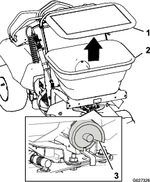
-
Remove the cover from the hopper, add the material that you are spreading, and install the cover onto the hopper (Figure 31).
Note: Do not overload the hopper; the maximum weight capacity of the hopper is 79 kg (175 lb).
Note: You may place 1 extra bag of granular product on top of the sprayer tank if necessary.
Emptying the Spreader
Removing the Impeller
-
Move the machine to a level surface, move motion-control lever to the NEUTRAL position, shut off the engine, wait for all moving parts to stop, remove key, and engage parking brake.
-
Empty the hopper by scooping out as much of the material as possible.
-
Remove the 4 thumbscrews that secure the front cover ( below the impeller) to the chassis, and remove the cover (Figure 32).
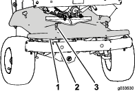
-
Remove the drive pin that secure the impeller to the shaft of the impeller motor, and remove the impeller from the shaft (Figure 33 and Figure 34).
-
Place a shallow pan under the shaft of the impeller motor (Figure 34).
Disconnecting the Rate-Gate Linkage
-
Push the locking sleeve for the gate cable rearward and lift the cable up from the ball stud of the rate-gate linkage (Figure 35).
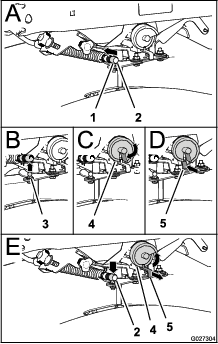
-
Pull the cable off the ball stud (Figure 35).
-
Rotate the drop-rate cam past position-9 so that the slot in the cam aligns with the linkage (Figure 35).
-
Fully push the rate-gate linkage rearward (Figure 35).
-
If there is material in the hopper allow the material to pour into a shallow pan; when the hopper is empty, remove the pan.
Connecting the Rate-Gate Linkage
Assembling the Impeller
-
Assemble impeller onto the impeller shaft and secure the impeller with the drive pin.
-
Align the holes in the front cover with the clip nuts in the chassis and secure the cover with the 4 thumbscrews that you removed in step 3 of Removing the Impeller.
Using the Spreader
Spreading Charts
Note: The cam setting tables for pellet material and the grass seed are provided with permission from the Brinly-Hardy Company; reference the Brinly-Hardy Company website for more information.
Use these charts as an approximate guideline only. Other factors, such as weather conditions, spreader operation, and the condition of material affects spreader performance.
| Type | kg per 93 m2 (lb per 1,000 ft2) | Cam Setting — One Pass | Cam Setting — Two Passes |
| Fine Pellets | 0.5 (1) | 3.6 | 3.1 |
| 0.9 (2) | 4.0 | 3.5 | |
| 1.4 (3) | 4.2 | 3.7 | |
| Mixed Fine Pellets | 0.9 (2) | 3.7 | 3.2 |
| 1.8 (4) | 4.7 | 4.1 | |
| 2.7 (6) | 5.2 | 4.5 | |
| Small Pellets | 0.9 (2) | 3 | 2.2 |
| 1.8 (4) | 4.2 | 3.7 | |
| 2.7 (6) | 4.5 | 4 | |
| Nitrogen Pellets Medium Size | 0.5 (1) | 3.5 | 3 |
| 0.9 (2) | 4.2 | 3.7 | |
| 1.4 (3) | 4.7 | 4 | |
| Medium Pellets and Granules | 0.9 (2) | 3.5 | 3 |
| 1.8 (4) | 4.2 | 3.8 | |
| 2.7 (6) | 5.2 | 4.5 | |
| Large Heavy Pellets | 0.9 (2) | 3.8 | 3.3 |
| 1.8 (4) | 4.9 | 4.1 | |
| 2.7 (6) | 5.9 | 4.9 |
Use the chart below for reference only. When spraying and spreading at the same time, set the spread pattern to twice the width of the spray; this will help avoid striping and streaking. For example, standard spray width = 2.7 m (9 ft) and spread width = 5.4 m (18 ft).
| Type | Bag Weight | Coverage - m2 (ft2) | Cam Setting – Full Rate | Cam Setting – Half Rate | Spreader Width |
|---|---|---|---|---|---|
| Blue Grass or Red Top | 0.23 kg (0.5 lb) | 93 (1,000) | 1.25 | 4 | |
| 0.45 kg (1 lb) | 93 (1,000) | 2.0 | 4 | ||
| 0.9 kg (2 lb) | 93 (1,000) | 2.5 | 4 | ||
| Park, Merion, Delta, or Kentucky Bluegrass | 2.27 kg (.5 lb) | 93 (1,000) | 2.5 | 4 | |
| 0.45 kg (1 lb) | 93 (1,000) | 3.0 | 4 | ||
| 0.9 kg (2 lb) | 93 (1,000) | 3.5 | 4 | ||
| Hulled Bermuda | 0.9 kg (2 lb) | 93 (1,000) | 2.75 | 2.25 | 6 |
| 1.36 kg (3 lb) | 93 (1,000) | 3.0 | 2.5 | 6 | |
| 1.81 kg (4 lb) | 93 (1,000) | 3.25 | 2.75 | 6 | |
| Mixtures Including Coarse Seeds | 0.9 kg (2 lb) | 93 (1,000) | 6.0 | 6 | |
| 1.81 kg (4 lb) | 93 (1,000) | 7.0 | 6 | ||
| 2.72 kg (6 lb) | 93 (1,000) | 7.0 | 6 | ||
| Rye Grasses or Tall Fescue | 0.9 kg (2 lb) | 93 (1,000) | 6.0 | 6 | |
| 1.81 kg (4 lb) | 93 (1,000) | 7.0 | 6 | ||
| 2.72 kg (6 lb) | 93 (1,000) | 7.75 | 6 | ||
| Dichondra | 113 kg (4 oz) | 93 (1,000) | 1.9 | 8 | |
| 227 g (8 oz) | 93 (1,000) | 2.1 | 8 | ||
| 340 g (12 oz) | 93 (1,000) | 2.5 | 8 | ||
| Pensacola Bahia | 1.81 kg (4 lb) | 93 (1,000) | 4.5 | 3.75 | 7 |
| 2.27 kg (.5 lb) | 93 (1,000) | 4.75 | 4.0 | 7 | |
| 2.72 kg (6 lb) | 93 (1,000) | 5.0 | 4.25 | 7 |
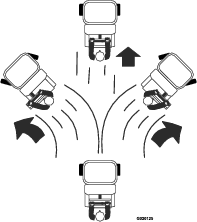
Adjusting the Spreader Pattern
If the spreader casts material unequally side-to side—too light/heavy to one side—(see Figure 36 and Figure 37), adjust the spreader-pattern.
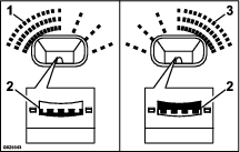
Note: Do not adjust the ramps that split the product flow. Adjust only the front or rear ramp positions.
Using the Deflector Gate
Use the deflector-gate control to temporarily stop or deflect granular material away from sidewalks, parking lots, patios, or anywhere the granular chemicals are not desired.
Note: The deflector gate changes the discharged of materials from the left side of the spreader only.
-
Push the knob for the deflector-gate control down to lower the deflector and temporarily block the granular material.
-
Pull the knob to raise the deflector to cast materials normally at the left side of the machine.
Spreading Material
-
Start the engine, and adjust the throttle midway between the SLOW and the FAST positions (Figure 39).
-
Tap the top of the impeller control switch to run the impeller motor (Figure 39).
Note: The spreader controller runs the impeller motor at the last speed setting to which you adjusted it.
-
Move the throttle to the FAST position, and drive the machine forward.
-
Open the either the narrow or wide impeller-gate lever to begin spreading (Figure 40).
Note: Use the flow-rate adjustment knob to control the discharge rate of the granular material from the hopper onto the impeller when the light distribution granular-gate lever is in the OPEN position.
-
Evaluate the spread pattern.
Note: If you need to adjustment the spreading pattern, refer to Adjusting the Spreader Pattern.
-
When you are finished spreading, close the heavy distribution granular-gate lever.
Note: Only the heavy distribution granular-gate lever closes the impeller gate. Pushing the heavy distribution granular-gate lever forward also resets the light distribution granular-gate lever to the forward position.
-
Clean the hopper after each spreading session; refer to Cleaning and Lubricating the Spreader.
Important: Always empty and clean the spreader immediately after each use. Failure to do so may cause the chemicals to corrode the spreader and other components.
Spreading Tips
Important: Ensure that you calibrate the spreader before you start using it.
-
To ensure uniform application, broadcast the material in an overlapping pattern as shown in Figure 41.
Note: The highest amount of material will dispense from the front of the hopper and less material from each side. You can adjust the distribution pattern to achieve the desired results.
-
Watch for changes in the distribution pattern; unequal distribution may lead to striping.
Operating the Sprayer
Caution
Chemicals are hazardous and can cause personal injury.
-
Read the chemical manufacturer’s directions on the label before handling the chemicals; follow all manufacturer recommendations and precautions.
-
Keep chemicals away from your skin. Should contact occur, wash the affected area thoroughly with soap and clean water.
-
Wear eye protection, gloves, and any other protective equipment recommended by the chemical manufacturer.
Use the sprayer to disperse liquid herbicides, pesticides, fertilizers, and other substances. Before using the sprayer ensure that you have cleaned the tank, plumbing, and nozzles before adding any chemicals. When you use the sprayer, you first fill the spray tank, then apply the chemical solution to the work site, and then when you are finished spraying, clean the tank. It is important to complete all 3 of these steps to avoid damaging the sprayer. For example, Do not mix and add chemicals in the spray tank the night before and then spray in the morning. This could lead to separation of the chemicals and possible cause damage to components of the sprayer.
Important: When you use your sprayer, thoroughly clean it at the end of the day.
Using the Sprayer and Information Display
 Sprayer |  Hour meter |
 Battery Voltage |  Voltage Error |
Motor Overcurrent Error | Motor Wire Fault |
Motor Open Error |
Sprayer Information Screens
LED Lights
The LED is multi-colored to indicate the system status and is located on the right side of the panel.
-
Solid Green — indicates normal operating activity.
-
Solid Red — indicates a fault is active.
Sprayer Start-Up Screens
When the key is switched to the RUN position, the sprayer and information display shows the following screens, each for 2 seconds:
Note: As each screen displays, the LED status light changes to green.


Default Sprayer Screen
The default sprayer screen (Figure 46) displays after the start-up screens display.
The hour meter records engine hours when the hourglass symbol flashes. After you turn the key to the OFF position, the display shuts off after 3 seconds.
Sprayer Operation Screen
The sprayer operation screen (Figure 47) displays when you tap the sprayer-pump switch.
Using the Sprayer-Pump Switch
Use the sprayer-pump switch (Figure 48) to start the electric motor that drives the sprayer pump and recirculation pump, adjust the sprayer system pressure, and shut off sprayer pump and recirculation pump motors.
-
Tap the top of the sprayer-pump switch to start the spray pump.
-
Tap the top of the sprayer-pump switch to raise the spray-system pressure.
-
Tap the bottom of the sprayer-pump switch to lower spray-system pressure.
-
Push the bottom of the sprayer-pump switch for 1-second to shutoff the spray pump.
Calibrating the Sprayer
Note: Before you use the sprayer for the first time or change the nozzles or when the sprayer is out of adjustment—calibrate the sprayer for ground speed and flow rate.
Note: The left and right sprayer boom nozzles are wide pattern (white) nozzles and the center nozzle is a narrow pattern (red) nozzle.
Note: Refer to the chemical product label for application rate recommendations.
The method to calibrate the sprayer flow involves driving a preset distance, recording the time, and then measuring the amount of liquid applied during that time.
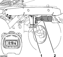
Calculating the Ground Speed
Operator supplied equipment: Stop watch capable of measuring ± 1/10 second.
-
Measure and visibly mark a course length used to calculate the average ground speed. Record the course length here: .
Note: In this example the course length is 45.7 m (150 ft).
-
Add clean water into the spray tank until it is 1/2 full; refer to Filling the Spray Tank.
-
Drive the machine to an area far enough away from the course so that when you are driving it into the course, the machine travels at the desired ground speed before reaching the first marker.
-
Use a stop watch to measure the time (in seconds) that it takes the machine to travel the marked course (45.7 m (150 ft) in this example) while maintaining the desired ground speed. Record your course time in the course time worksheet.
Course Time Worksheet
Time Test 1 seconds Test 2 seconds Test 3 seconds -
Repeat steps 2 through 4 an additional 2 times.
-
Move the sprayer to a level surface, move the motion-control lever in the NEUTRAL position, shut off the engine, wait for all moving parts to stop, remove key, and engage parking brake.
-
Average the 3 test run times (in seconds); use the average course time formula. Record the average course speed here: .
Average Course Time Formula
Formula (time 1) + (time 2) + (time 3) seconds = The average time to drive the course 3 Example 21.6 + 19.1+ 18.4 seconds = 19.7 seconds 3 -
Calculate the average ground speed; use the ground speed formula. Record the average ground speed here: .
Note: 1 kph = 16.6 m/minute (1 mph = 88 ft/minute)
Ground Speed Formula
Formula Course lengthm (ft) x 60 seconds = Ground speed kph (mph) Course time (seconds) x16.7 m/minute (88 ft/minute) Example 45.7 m (150 ft) x 60 seconds = 8.4 kph(5.2 mph) 19.7 seconds x 16.6 m/minute (88 ft/minute)
Understanding the Effective Spray Pattern Width
Testing the Sprayer Nozzle Discharge
Operator supplied equipment: Have a stop watch capable of measuring ± 1/10 second and a container graduated in 50 ml (1 fl oz) increments.
Note: Ensure that the spray system is clean and there is 1/2 tank of clean water.
-
Engage the parking brake and start the engine.
-
Set the sprayer-pump switch to the ON position.
-
Pull the tank-agitation lever to start the tank agitation.
-
Move the throttle to the FAST position.
-
Push the tank-agitation lever to the OFF position.
Note: Shut off the agitation to ensure proper spray pressure and distribution.
-
Use the sprayer—pump switch to adjust the sprayer-system pressure to 40 psi (2.8 bar).
Note: The red and white nozzles installed on this sprayer have a normal operating pressure of 40 psi (2.8 bar).
-
Align the graduated container under each nozzle for 19.7 seconds.
Note: Record the amount of water collected from each nozzle in the collection worksheet.
Collection Worksheet
Left sprayer nozzle Center sprayer nozzle Right sprayer nozzle Test 1 ml (fl oz) ml (fl oz) ml (fl oz) Test 2 ml (fl oz) ml (fl oz) ml (fl oz) Test 3 ml (fl oz) ml (fl oz) ml (fl oz) -
Repeat test step 7 for each nozzle an additional 2 times.
-
Set the sprayer-pump switch to the OFF position.
-
Calculate the average quantity of water discharged for each nozzle; use average discharge formula.
Average Discharge Formula
Formula test 1 + test 2 + test 3 = The average spray nozzle discharge in 19.7 seconds 3 Example center nozzle—narrow pattern (red) 475 ml (16.05 fl oz) + 507 ml (17.15 fl oz) + 504 ml (17.05 fl oz) = 0.49 L (16.75 fl oz) 3 -
Right nozzle—record the average discharge quantity here: .
-
Center nozzle—record the average discharge quantity here: .
-
Left nozzle—record the average discharge quantity here: .
-
Converting the Time and Collection Results to Flow Rate
-
Convert the milliliters (fluid ounce) quantities that you calculated in step 10 of Testing the Sprayer Nozzle Discharge to liters (US gallons) using the quantity conversion formula.
Note: 1 L = 1000 ml1 US gallon = 128 fl oz
Quantity Conversion Formula
Formula Result (X) ml (fl oz) = (X) L (US gallon) 0.1 L (128 fl oz) Example center nozzle—narrow pattern (red) 490 ml (16.75 fl oz) = 0.49 L (0.13 US gallon) 0.1 L (128 fl oz) -
Right nozzle—record the converted collected-water quantity here: .
-
Center nozzle—record the converted collected-water quantity here: .
-
Left nozzle—record the converted collected-water quantity here: .
-
-
Calculate the flow rate of each nozzle using the calculated flow-rate formula.
-
Calculated Flow-Rate Formula
Formula Result (X) L (US gallon) x 60 seconds = (X) L (US gallon) 19.7 seconds Example center nozzle—narrow pattern (red) .49 L (0.13 US gallon) x 60 seconds = 3.07 L (0.40 US gallon) per minute 19.7 seconds -
Right nozzle—record the calculated flow rate here: .
-
Center nozzle—record the calculated flow rate here: .
-
Left nozzle—record the calculated flow rate here: .
Note: If the collected nozzle spray does not meet the quantity in the Nozzle Application Rate Tables, check the nozzles, hoses, and fittings for leaks, damage, or wear; clean or replace the spray nozzles if needed.
-
Nozzle Application Rate Tables
Use the nozzle tables determine sprayer performance:
-
Nozzle flow rates at different spray-system pressures
-
Worn or damaged spray nozzles
The tables that follow include application rate information for TeeJet Turbo FloodJet® wide angle fat spray tips:
The table excerpt is provided with permission from TeeJet® Technologies; reference theTeeJet® Technologies website for more information.
Important: Do not use the green and black nozzles (not listed) with this machine because the nozzles exceed the spray pump capacity.
The nozzle application rate information is based on water sprayed at 21°C (70°F).
|
Spray Pressure |
Single Nozzle Rate |
||
|---|---|---|---|
|
0.7 Bar |
0.77 L/min |
0.20 gpm |
26 oz/min |
|
(10 psi) |
|||
|
1.4 Bar |
1.06 L/min |
0.28 gpm |
36 oz/min |
|
(20 psi) |
|||
|
2.1 Bar |
1.33 L/min |
0.35 gpm |
45 oz/min |
|
(30 psi) |
|||
|
2.8 Bar |
1.51 L/min |
0.40 gpm |
51 oz/min |
|
(40 psi) |
|||
|
Spray Pressure |
Single Nozzle Rate |
||
|---|---|---|---|
|
0.7 Bar |
0.95 L/min |
0.25 gpmgpm |
32 oz/min |
|
(10 psi) |
|||
|
1.4 Bar |
1.33 L/min |
0.35 gpm |
45 oz/min |
|
(20 psi) |
|||
|
2.1 Bar |
1.63 L/min |
0.43 gpm |
55 oz/min |
|
(30 psi) |
|||
|
2.8 Bar |
1.89 L/min |
0.50 gpm |
64 oz/min |
|
(40 psi) |
|||
|
Spray Pressure |
Single Nozzle Rate |
||
|---|---|---|---|
|
0.7 Bar |
1.12 L/min |
0.30 gpm |
38 oz/min |
|
(10 psi) |
|||
|
1.4 Bar |
1.60 L/min |
0.42 gpm |
54 oz/min |
|
(20 psi) |
|||
|
2.1 Bar |
1.98 L/min |
0.52 gpm |
67 oz/min |
|
(30 psi) |
|||
|
2.8 Bar |
2.28 L/min |
0.60 gpm |
77 oz/min |
|
(40 psi) |
|||
|
Spray Pressure |
Single Nozzle Rate |
||
|---|---|---|---|
|
0.7 Bar |
1.51 L/min |
0.40 gpm |
51 oz/min |
|
(10 psi) |
|||
|
1.4 Bar |
2.16 L/min |
0.57 gpm |
73 oz/min |
|
(20 psi) |
|||
|
2.1 Bar |
2.61 L/min |
0.69 gpm |
88 oz/min |
|
(30 psi) |
|||
|
2.8 Bar |
3.02 L/min |
0.80 gpm |
102 oz/min |
|
(40 psi) |
|||
|
Spray Pressure |
Single Nozzle Rate |
||
|---|---|---|---|
|
0.7 Bar |
1.89 L/min |
0.50 gpm |
64 oz/min |
|
(10 psi) |
|||
|
1.4 Bar |
2.69 L/min |
0.71 gpm |
91 oz/min |
|
(20 psi) |
|||
|
2.1 Bar |
3.28 L/min |
0.87 gpm |
111 oz/min |
|
(30 psi) |
|||
|
2.8 Bar |
3.79 L/min |
1.00 gpm |
128 oz/min |
|
(40 psi) |
|||
Determining Application Rate
Use the example results of the calculated speed, spray width, and nozzle capacity to determine the application rate.
Note: The application rate may also be determined by using the Nozzle Application Rate Tables, along with the chemical manufacturer’s label of recommendation.
The examples below are based on the following information:
-
Average ground speed = 8.4 kph (5.2 mph)
-
Spray width = 2.7 m (108 inches)
-
Number of nozzles = 2
-
Nozzle capacity = 3.0 L/min (0.8 gpm)
Note: The numbers 6 and 600 are constants used in the formulas shown below.
| Single nozzle capacity (Lpm) x Number of nozzles x 6 | = | L |
| Speed (kph) x Spray width (m) | 100 m2 |
| 2.99 Lpm x 2 x 6 | = | 1.563 L/100 m2(1.5 qt/1,000 ft2) |
| 8.369 kph x 2.743 m |
| Single nozzle capacity (Lpm) x Number of nozzles x 600 | = | L |
| Speed (kph) x Spray width (m) | hectar |
| 2.99 Lpm x 2 x 600 | = | 156 L/hectar(16.7 gal/acre) |
| 8.369 kph x 2.743 m |
Note: The numbers 544; 136; and 5,940 are constants used in the formulas shown below.
| Single nozzle capacity (gpm) x Number of nozzles x 544 | = | qt |
| Speed (mph) x Spray width (inches) | 1,000 ft2 |
| 0.79 gpm x 2 x 544 | = | 1.5 qt/1,000 ft2(1.5 L/100 macre2) |
| 5.2 mph x 108 inches |
| Single nozzle capacity (gpm) x Number of nozzles x 136 | = | gal |
| Speed (mph) x Spray width (inches) | 1,000 ft2 |
| 0.79 gpm x 2 x 136 | = | 0.38 gal/1,000 ft2(1.5 L/100 m2) |
| 5.2 mph x 108 inches |
| Single nozzle capacity (gpm) x Number of nozzles x 5,940 | = | gal |
| Speed (mph) x Spray width (inches) | acre |
| 0.79 gpm x 2 x 5,940 | = | 16.7 gal/acre(156.1 L/ha) |
| 5.2 mph x 108 inches |
Using the Sprayer
Before Operating the Sprayer
Some chemicals are more aggressive than others and each chemical interacts differently with various materials. Some consistencies of sprayer chemicals (e.g. wettable powders, charcoal) are more abrasive and lead to higher-wear rates. If a chemical is available in a formulation that would provide increased life to the sprayer, use this alternative formulation.
Calibrate the sprayer before you start the spray application; refer to Calibrating the Sprayer.
Filling the Spray Tank
Important: Ensure that the chemicals that you are using in the sprayer are compatible for use with O-rings and seals made from fluoroelastomer material (refer to the chemical manufacturer's label; it should indicate if it is not compatible). If you use a chemical that is not compatible with fluoroelastomer material, the O-rings and seals in the sprayer can degrade and leak.
Important: Do not use brackish or reclaimed water in the spray system.
Important: Before applying chemicals to the job site, verify that you have set the proper application rate prior to filling the tank.
-
Move the machine to a level surface, move motion-control lever to the NEUTRAL position, shut off the engine, wait for all moving parts to stop, remove key, and engage parking brake.
-
Ensure that the narrow-spray pattern and wide-spray pattern levers are in the OFF position and the handle for the drain valve for the tank rotated 90° counterclockwise to the is CLOSED position (Figure 52).
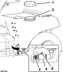
-
Determine the amount of water needed to mix the amount of chemical needed as specified by the chemical manufacturer.
-
Open the tank cap on the spray tank (Figure 52).
-
Add 3/4 of the required water to the sprayer tank through the filler neck.
Important: Always use fresh, clean water in the spray tank. Do not pour chemical concentrate into an empty tank.
-
Rotate the pump-shutoff valve clockwise to the OPEN position (Figure 53).
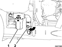
-
Start the engine and set the throttle midway between the SLOW and FAST positions.
-
Set the sprayer-pump switch to the ON position (Figure 54).
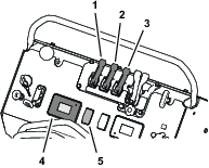
-
Move the throttle to the FAST position.
-
Pull the tank-agitation lever to the ON position.
Note: The water in the tank will circulate.
-
Add the specified amount of chemical concentrate to the tank as directed by the chemical manufacturer.
Important: If you are using a wettable-powder chemical, mix the powder with a small amount of water to form a liquid slurry before adding the chemical mixture to the tank.
-
Add remaining water to the tank and install cap onto the filler neck of the tank.
Note: Allow the content of the sprayer tank to mix thoroughly.
Emptying the Sprayer Tank
Operator supplied equipment:
-
A drain hose with a 1/2–14 inch NPT male coupling
-
A drain container (capacity varies with remaining sprayer tank content)
-
PTFE thread sealant
-
Move the machine to a level surface at the designated area for emptying and cleaning the sprayer tank, move motion-control lever to the NEUTRAL position, shut off the engine, wait for all moving parts to stop, remove key, and engage parking brake.
-
Remove the plug from the drain valve for the sprayer tank (Figure 55).
Note: The drain valve is located at the left side of the machine.
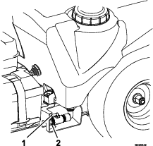
-
Thread a drain hose (operator provided) into the end of the drain valve.
-
Put the free end of the drain hose into a container with enough capacity to hold the remaining content of the sprayer tank.
Note: Use the quantity marks at the front, left side of the sprayer tank for determine the quantity of chemical solution in the tank.
-
Rotate the handle for the drain valve clockwise 90° to drain the tank (Figure 55).
Allow the sprayer tank to drain completely.
-
Apply PTFE thread sealant to the threads of the plug.
-
Close the tank-drain valve, remove the drain hose, and install the drain plug into the valve (Figure 55).
Note: Dispose of the sprayer chemicals according to local codes and the chemical manufacturer's instructions.
Spraying with the Sprayer Boom
Important: To ensure that your chemical solution remains well mixed, use the agitation feature whenever you have solution in the tank. For the agitation feature to work, set the sprayer-pump switch to the ON position, pull back the tank-agitation lever, and run the engine at high idle. If you shut off the machine and agitation is needed, leave the motion-control lever in the NEUTRAL position, engage the parking brake, increase the throttle to the FAST position, start the sprayer pump and run tank agitation.
Note: Calibrate the sprayer before you start the spray application; refer to Calibrating the Sprayer.
-
Tap the sprayer-pump switch to the ON position.
-
Drive the machine to the job site.
-
Push the tank-agitation lever to the OFF position.
Note: There is some agitation effect even while the tank-agitation lever is in the OFF position.
-
Use the sprayer-pump switch to adjust the spray pressure to the setting that you determined in Nozzle Application Rate Tables.
-
Move the narrow or wide-spray pattern lever to the ON position and begin spraying.
Important: Do not use both the narrow and wide controls at the same time.
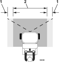
-
When you finish spraying, push forward the spray-pattern levers and set the sprayer-pump switch to the OFF position.
Note: If you need to continue to mix the sprayer tank contents, leave the sprayer-pump switch in the ON position, and pull the tank-agitation lever.
Spraying Tips
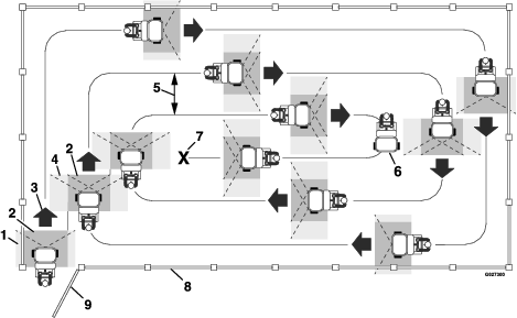
-
Do not overlap the effective spray area that you have previously sprayed (see Figure 58).
-
Watch for plugged sprayer nozzles.
-
Move the narrow-and wide-spray pattern levers to the OFF position to stop the spray flow before stopping the motion of the machine. Once stopped, leave the motion-control lever in NEUTRAL and leave the sprayer-pump switch in the ON position.
-
You obtain better results if the machine is moving when spray controls are turned ON.
-
Ensure adequate pump pressure for proper spray distribution by push the tank-agitation lever to the OFF position.
-
Watch for changes in the application rate. Changes in the application rate indicate that your ground speed has changed beyond the operating range of the nozzles or there is a problem with the sprayer system.
Note: When the tank is nearly empty, the tank agitation may cause foaming of the chemical solution in the tank. In this case, push the tank-agitation lever to the OFF position. Alternatively, if an anti-foaming agent compatible with the existing chemical—add the anti-foaming agent according to the manufacturer’s instructions.
Spraying with the Spray Wand
Warning
The spray wand traps liquids under high pressure, even when engine is off. High-pressure spray discharge could cause serious injury or death.
-
Keep clear of the nozzle and do not direct the spray or stream from the wand at people, pets, or non-work area property.
-
Do not direct the spray at or near electrical-power components or source.
-
Do not repair the spray wand, hoses, seals, nozzle, or other wand components; always replace them.
-
Do not attach the hoses or other components to the nozzle at the end of the spray wand.
-
Do not attempt to disconnect the spray wand from the machine while the sprayer system is pressurized.
-
Do not use the spray wand if trigger lock is damaged or missing.
-
Rotate the spray-wand lock to the OFF position when job is complete.
-
Remove the wand from the holder at the right side of the machine (Figure 59).
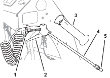
-
Firmly grip the spray wand and point it in the direction that you will spray.
Note: The wand may recoil; ensure that you hold it securely.
-
Adjust the pump pressure to the spray wand perform the following:
-
To increase the pump pressure to the wand, rotate the wand-pressure control counterclockwise (Figure 60).
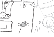
-
To decrease pressure to the wand, rotate the wand-pressure control clockwise direction (Figure 60).
-
Fully open the wand-pressure control, and use the sprayer-pump switch to adjust pressure to the wand.
-
To shut off the pressure to the wand, rotate the wand-pressure control clockwise until the valve for the control is closed (Figure 60).
-
-
Squeeze the trigger to the spray-wand handle to begin spraying; lock the trigger in place if desired (Figure 59).
-
When finished spraying, if you locked the trigger of the spray-wand—unlock it, and release the trigger (Figure 59)
-
Rotate the sprayer-wand pressure control clockwise to the OFF position (Figure 60).
-
Insert the wand into the wand holder (Figure 59).
After Operation
After Operation Safety
General Safety
-
Park the machine on level ground and allow it to cool. Never allow untrained personnel to service the machine.
-
Disengage the spray or close the spreader gate, set the parking brake, shut off the engine, and remove the key or disconnect the spark-plug wire. Wait for all movement to stop before adjusting, cleaning or repairing the machine.
-
Clean the machine as stated in Cleaning and Lubricating the Spreader and Cleaning the Sprayer
-
Frequently check for worn or deteriorating components that could create a hazard. Tighten loose hardware.
-
Shut off the fuel when storing or transporting the machine. Do not store fuel near flames or drain fuel indoors.
Cleaning and Lubricating the Spreader
| Maintenance Service Interval | Maintenance Procedure |
|---|---|
| After each use |
|
Important: Do not use brackish or reclaimed water to clean the machine.
-
Drive the machine to a designated cleaning area with a level surface.
-
Move the motion-control lever in the NEUTRAL position, shut off the engine, wait for all moving parts to stop, remove key, and engage parking brake.
-
Empty the hopper; refer to Emptying the Spreader.
-
Using a hose to spray the inside and outside of the entire spreader with clean water.
Note: Do not use a power washer to clean the machine. The high-pressure water can force residual-corrosive materials into sprayer-spreader components.
-
Tilt the screen at the bottom of the hopper forward to clean the bottom hopper components (Figure 61).
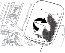
-
Rotate the hopper screen down.
-
Disconnect the hopper rate-gate cable, place the rate gate dial to a setting lower than the maximum open position, and allow the spreader-sprayer to empty completely; refer to Emptying the Spreader.
-
Connect the hopper rate-gate cable; refer to Connecting the Rate-Gate Linkage.
-
Apply water-displacing lubricant to the components as shown in Figure 62.
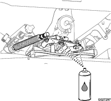
Cleaning the Sprayer
| Maintenance Service Interval | Maintenance Procedure |
|---|---|
| After each use |
|
Warning
Swallowing or inhaling chemicals could cause serious injury or death.
-
Do not clean sprayer nozzles using your mouth or blowing through the nozzles.
-
Replace all worn and damaged sprayer nozzles.
-
Ensure that the nozzles are installed correctly.
Important: Do not use brackish or reclaimed water to clean the machine.
Preparing the Machine
-
Empty the sprayer tank; refer to Emptying the Sprayer Tank.
-
Fill the sprayer tank with 19 L (5 US gallons) or more of clean water and install the cap; refer to Filling the Spray Tank.
-
Engage the parking brake, move the steering-control/motion-control lever to the NEUTRAL position, and start the engine (Figure 63); refer to Starting the Engine.
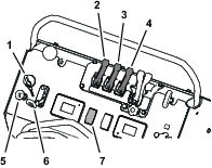
-
Tap the sprayer-pump switch to the ON position, and set the engine throttle to FAST position (Figure 63).
-
Pull the tank-agitation lever to the ON position (Figure 63).
Cleaning the Sprayer System and Wand
Important: Always empty and clean the sprayer immediately after each use. Failure to do so may cause the chemicals to dry or thicken in the lines, clogging the pump and other components.
-
Pull back both narrow and wide-spray pattern levers to the ON position (Figure 63).
The sprayer nozzles begin spraying.
-
Allow the rinse water in the tank to spray through the nozzles.
-
Check that all 3 nozzles are spraying correctly.
-
Remove the sprayer wand from the holder, point the wand in a safe direction, and squeeze the trigger; refer to Spray-Wand Trigger and Trigger Lock.
Note: Allow the rinse water to discharge from the wand for 1 to 2 minutes.
-
Release the trigger for the wand and return it to the holder on the machine (Figure 8).
-
Move the spray-pattern levers forward to the OFF position, set the sprayer-pump switch to the OFF position, and shut off the engine (Figure 63).
-
Clean the strainer; refer to Cleaning the Strainer.
-
Repeat steps 2 through 7 using cleaners and neutralizers recommended by the chemical manufacturers; refer to Filling the Spray Tank.
-
Repeat steps 2 through 7 using clean water only.
Cleaning the External Components
-
Using a hose to wash off the outside of the sprayer tank with clean water.
Note: Do not use a power washer to clean the machine. The high-pressure water may force residual corrosive materials into spreader-spreader components.
-
Remove and clean the sprayer nozzles; refer to Cleaning the Sprayer Nozzle.
Note: Replace damaged or worn nozzles.
-
Allow the spreader-sprayer to completely dry before the next use.
Cleaning the Strainer
| Maintenance Service Interval | Maintenance Procedure |
|---|---|
| After each use |
|
Important: If you used wettable-powder chemicals, clean the strainer after each time that you rinse the sprayer tank.
-
Empty the sprayer tank; refer to Emptying the Sprayer Tank.
-
Rotate the handle of the pump-shutoff valve 90° counterclockwise to the CLOSE position (Figure 64).
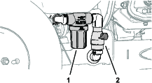
-
Align a drain pan under the strainer (Figure 64).
-
Rotate the strainer bowl counterclockwise and remove the bowl and screen from the body of the strainer (Figure 65).
Note: Remove the strainer bowl by hand.
Note: Replace the gasket or screen or both if these parts are worn or damaged.
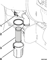
-
Allow any residual chemical solution to drain from the strainer body.
Note: Dispose of the waste solution according to local codes and the chemical manufacturer's instructions.
-
Use a soft-bristle brush and clean water to clean the screen and bowl.
-
Install the screen into the strainer body (Figure 65).
-
Install the gasket and strainer bowl onto the strainer body, and hand tighten the bowl (Figure 65).
-
Rotate the handle of the pump-shutoff valve 90° clockwise to the OPEN position (Figure 64).
Cleaning the Sprayer Nozzle
| Maintenance Service Interval | Maintenance Procedure |
|---|---|
| After each use |
|
-
Rotate the nozzle cap 90° counterclockwise and remove the cap from the nozzle body (Figure 66).
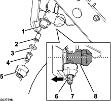
-
Remove the sprayer tip, gasket, and strainer from the nozzle body (Figure 66).
Note: Replace any worn or damaged nozzle parts.
-
Use a soft-bristle brush and clean water to clean the nozzle tip, gasket, and strainer.
-
Assemble the strainer into the nozzle body (Figure 66).
-
Assemble the sprayer tip and gasket into the nozzle cap (Figure 66).
-
Install the tip, gasket, and cap onto the nozzle body (Figure 66).
Note: Use the slot to rotate the atomizer (Figure 66) of the sprayer tip forward (in-line with the flow-regulator case of the nozzle body).
-
Rotate the nozzle cap 90° clockwise (Figure 66).
-
Repeat steps 1 through 7 for the 2 other sprayer nozzles.
Transporting the Machine
Machine weight: 227 kg (500 lb)—both sprayer tank and hopper empty; 389 kg (857 lb)—both sprayer tank and hopper full
Caution
This machine does not have turn signals, lights, reflective markings, or a slow moving vehicle emblem. Driving on a street or roadway without such equipment is dangerous and can lead to accidents causing personal injury.
Do not drive the machine on a public street or roadway.
Note: Refer to the chemical warning product label(s) before transporting the machine and follow all local/state/federal requirements for transporting chemicals.
Note: Make sure that the spreader hopper cover and the spray wand are secure before transporting.
Loading the Machine
Warning
Loading a machine onto a trailer or truck increases the possibility of tip-over and could cause serious injury or death.
-
Use extreme caution when operating a machine on a ramp.
-
Back the machine up the ramp and walk it forward down the ramp.
-
Avoid sudden acceleration or deceleration while driving the machine on a ramp as this could cause a loss of control or a tip-over situation.
-
Do not attempt to turn the machine while on the ramp; you may lose control and drive off the side.
-
Use only a single, full-width ramp; do not use individual ramps for each side of the machine.
-
If you must use individual ramps, use enough ramps to create an unbroken ramp surface wider than the machine.
Use a heavy-duty trailer or truck to transport the machine. Ensure that the trailer or truck has all the necessary brakes, lighting, and marking as required by law. Please carefully read all the safety instructions.
-
If using a trailer, connect it to the towing vehicle and connect the safety chains.
-
If applicable, connect the trailer brakes.
-
Lower the ramp.
-
Raise the operator platform.
-
Back the machine up the ramp (Figure 67).

-
Secure the machine; refer to Securing the Machine for Transport.
Securing the Machine for Transport
Warning
Securing the machine at any upper frame location could cause the parking brake to not function properly, which could cause serious injury or death.
Only use the front tie-down locations at the lower frame to secure the front of the machine.
Only use the rear tie-down locations at the back of the frame to secure the back of the machine.
Note: Refer to the chemical-warning-product label(s) before transporting the machine and follow all local/state/federal requirements for transporting chemicals.
Note: Ensure that the spreader-hopper cover and the spray wand are secure before transporting.
-
At the left side of the machine, ensure that the shutoff valve for the sprayer tank is closed and the drain plug is secure. At the right side of the machine, ensure that the pump-shutoff valve is closed.
-
Shut off the engine, remove the key, and engage the parking brake.
-
Close the fuel valve and block the tires.
-
Use the tie-down points on the machine to securely bind the machine to the trailer or truck with straps, chains, cable, or ropes (Figure 68). Refer to local regulations for trailer and tie-down requirements.

Maintenance
Maintenance Safety
-
While performing maintenance on the machine, someone could start the engine. Accidental starting of the engine could seriously injure you or others. Remove the key from the ignition switch, engage parking brake, and pull the wire(s) off the spark plug(s) before you do any maintenance. Also, push the wire(s) aside so that it does not accidentally contact the spark plug(s).
-
The engine can become very hot. Touching a hot engine can cause severe burns. Allow the engine to cool completely before servicing or repairing around the engine area.
-
Park the machine on level ground and allow it to cool. Never allow untrained personnel to service the machine.
-
Disengage the spray or close the spreader gate, set the parking brake, shut off the engine, and remove the key or disconnect the spark-plug wire. Wait for all movement to stop before adjusting, cleaning, or repairing the machine.
-
Disconnect the battery or remove the spark-plug wire before making any repairs. Disconnect the negative terminal first and the positive terminal last. Connect positive terminal first and negative terminal last.
-
Relieve the pressure from the spray system before servicing the machine.
-
Empty the tank and/or hopper before tilting the machine for maintenance and before storage.
-
Hydraulic fluid escaping under pressure can penetrate skin and cause injury. Fluid accidentally injected into the skin must be surgically removed within a few hours by a doctor familiar with this form of injury; otherwise, gangrene may result.
-
If equipped, ensure that all hydraulic fluid hoses and lines are in good condition and that all hydraulic connections and fittings are tight before applying pressure to the hydraulic system.
-
Keep your body and hands away from pinhole leaks or nozzles that eject high-pressure hydraulic fluid.
-
Use cardboard or paper, not your hands, to find hydraulic leaks.
-
Safely relieve all pressure in the hydraulic system by placing the motion-control levers in neutral and shutting off the engine before working on the hydraulic system.
-
-
Raising the machine for service or maintenance relying solely on mechanical or hydraulic jacks could be dangerous. The mechanical or hydraulic jacks may not be enough support or may malfunction, allowing the machine to fall and cause possible injury. Do not rely solely on mechanical or hydraulic jacks for support. Use adequate jack stands or equivalent support.
-
Carefully release the pressure from components with stored energy.
-
Keep your hands and feet away from moving parts. If possible, do not make adjustments while the engine is running. If the maintenance or adjustment procedure requires the engine to be running and components moving, use extreme caution.
-
Contact with moving parts or hot surfaces may cause personal injury. Keep your fingers, hands, and clothing clear of rotating components and hot surfaces.
-
Check all bolts frequently to maintain their proper tightness.
Recommended Maintenance Schedule(s)
| Maintenance Service Interval | Maintenance Procedure |
|---|---|
| After the first 10 hours |
|
| Before each use or daily |
|
| After each use |
|
| Every 50 hours |
|
| Every 80 hours |
|
| Every 100 hours |
|
| Monthly |
|
| Yearly |
|
| Yearly or before storage |
|
Notation for Areas of Concern
| Inspection performed by: | ||
| Item | Date | Information |
| 1 | ||
| 2 | ||
| 3 | ||
| 4 | ||
| 5 | ||
| 6 | ||
| 7 | ||
| 8 | ||
Important: Refer to your engine owner’s manual for additional maintenance procedures.
Pre-Maintenance Procedures
Preparing the Machine
Warning
While you are maintaining or adjusting the machine, someone could start the engine. Accidentally starting the engine could seriously injure you or other bystanders.
Remove the key from the ignition, engage parking brake, and pull the wire(s) off the spark plug(s) before you do any maintenance. Also push the wire(s) aside so it does not accidentally contact the spark plug(s).
Perform the following before servicing, cleaning, or making any adjustments to the machine.
-
Park the machine on a level surface.
-
Shut the wide-distribution impeller-gate for the spreader and shut off the sprayer-pump switch.
-
Shut off the engine and remove the key.
-
Engage the parking brake.
-
Wait for all moving parts to stop allow the engine to cool before servicing, storing, or making repairs.
-
Disconnect the spark-plug wire (Figure 69).
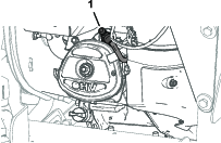
Lubrication
Lubricating the Grease Fittings
| Maintenance Service Interval | Maintenance Procedure |
|---|---|
| Every 100 hours |
|
Grease type: National Lubricating Grease Institute (NGLI) grade No. 2 multi-purpose gun grease.
-
Prepare the machine for maintenance; refer to Preparing the Machine.
-
Wipe the grease fittings clean with a rag (Figure 70).
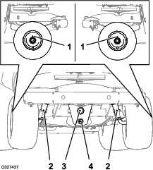
-
Connect a grease gun to the fittings (Figure 70).
-
Pump grease into the fittings until grease begins to come out of the bearings.
-
Wipe up any excess grease.
Engine Maintenance
Servicing the Air Cleaner
| Maintenance Service Interval | Maintenance Procedure |
|---|---|
| Before each use or daily |
|
| Every 100 hours |
|
Important: Do not operate the engine without the air filter assembly; extreme engine damage may occur.
Removing the Foam and Paper Elements
-
Move motion-control lever to the NEUTRAL position, shut off the engine, wait for all moving parts to stop, remove key, and engage parking brake.
-
Release the latches on the cover for the air cleaner.
-
Remove the cover and thoroughly clean it ().
Note: Be careful to prevent dirt and debris from falling into the base.
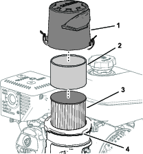
Cleaning the Foam Filter Element
-
Remove the foam pre-cleaner from the paper element.(Figure 71).
-
Wash the pre-cleaner with warm water and a mild detergent.
-
Rinse the pre-cleaner and allow it to air dry.
-
Lightly oil pre-cleaner with new engine oil; squeeze out excess oil.
Installing the Foam and Paper-Filter Elements
-
Remove and inspect the paper air-filter element (); if the air-filter element is excessively dirty, replace it.
Important: Do not to clean the air-filter element.
-
Wipe clean the air-filter base with a moist rag.
Note: Be careful to prevent dirt and debris from entering the air duct leading to the carburetor.
-
Install the foam pre-cleaner onto the air-filter element (Figure 71).
-
Install the air filter assembly to the air-filter base (Figure 71).
-
Align the arrow decal on the air-cleaner cover and the arrow decal on the base (Figure 72).
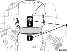
-
Secure the air-filter cover to the base with the latches.
Engine Oil Specification
Oil Type: Toro 4-Cycle Premium Engine Oil or a high-quality detergent oil (including synthetic) API service SJ or higher
Oil viscosity: Refer to the table below.
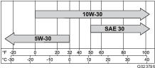
Checking the Engine-Oil Level
| Maintenance Service Interval | Maintenance Procedure |
|---|---|
| Before each use or daily |
|
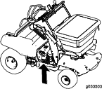
Important: Do not operate the engine with the oil level below the Low (or Add) mark on the dipstick, or over the Full mark.
-
Move the machine to a level surface.
-
Prepare the machine for maintenance; refer to Preparing the Machine.
-
Allow the engine to cool.
-
Remove the dipstick from the engine and wipe the dipstick with a clean rag (Figure 75).
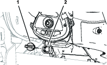
-
Insert the dipstick from the engine as shown in Figure 76.
Note: Do not thread the dipstick into the filler neck when checking the engine oil level.
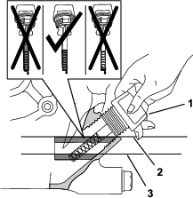
-
Remove the dipstick from the filler neck and look at the oil level in the dipstick (Figure 76).
Note: The engine oil level must cover the hatch-marked area of the dipstick (Figure 76).
-
If the oil level is low, wipe off the area around the filler neck and add the specified oil until the oil level is between the hatch marked areas on the dipstick.
Important: Do not overfill the engine with oil.
-
Hand tighten the dipstick into the filler neck (Figure 75).
Changing the Engine Oil
| Maintenance Service Interval | Maintenance Procedure |
|---|---|
| After the first 10 hours |
|
| Every 100 hours |
|
Draining the Engine Oil
-
Prepare the machine for maintenance; refer to Preparing the Machine.
-
Shut off the engine, remove the key, and wait for all moving parts to stop before leaving the operating position.
-
Align a drain pan with a capacity of 1.5 L (1.6 US qt) or greater below the drain valve at the bottom of the skid plate and inboard from the battery tray (Figure 77).
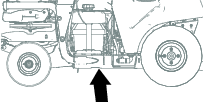
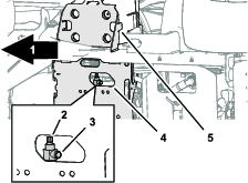
-
Open the drain valve by rotating the hex-head stem of the valve counterclockwise with a wrench (Figure 77).
Note: Allow the engine oil to drain completely.
-
Close the drain valve clockwise until the valve is fully seated (Figure 77).
Note: Wipe clean any residual oil from the drain valve.
Adding Engine Oil to the Engine
Important: Do not operate the engine with the oil level below the Low (or Add) mark on the dipstick, or over the Full mark.
-
Remove the dipstick from the filler neck of the engine and wipe clean the dipstick with a rag (Figure 78).
-
Slowly pour 1.1 L (1.2 US qt) of the specified oil into the crank case of the engine through the filler neck (Figure 78).
-
Insert the dipstick from the engine as shown in Figure 79.
Note: Do not thread the dipstick into the filler neck when checking the engine oil level.
-
Remove the dipstick from the filler neck and look at the oil level in the dipstick (Figure 79).
Note: The engine oil level must cover the hatch-marked area of the dipstick (Figure 79).
-
If the oil level is low, add the specified oil into the engine until the oil level is between the hatch marked areas on the dipstick.
Note: Do not overfill the engine with oil.
-
Hand tighten the dipstick into the filler neck (Figure 78).
Servicing the Spark Plug
Spark Plug Specification
Spark plug type: Champion® RC12YC, Kohler® 12 132 02-S, or Kohler 25 132 14-S (RFI compliant)
Removing the Spark Plug
-
Prepare the machine for maintenance; refer to Preparing the Machine.
-
Remove the spark plug as shown in Figure 80.
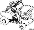
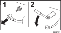
Checking the Spark Plug
Spark-plug gap: 0.76 mm (0.030 inch)
Important: Do not clean the spark plug(s). Always replace the spark plug(s) when it has a black coating, worn electrodes, an oily film, or cracks.
If you see light brown or gray on the insulator, the engine is operating properly. A black coating on the insulator usually means the air cleaner is dirty.
Use a gapping tool/feeler gauge to check and adjust the air gap to 0.76 mm (0.030 inch).
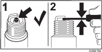
Installing the Spark Plug
Tighten the spark plug as follows:
-
New spark plug—12 to 15 N∙m (8.7 to 10.8 ft-lb)
-
In-service spark plug—23 to 27 N∙m (16.6 to 19.5 ft-lb)
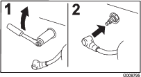
Cleaning the Spark Arrester
Required parts: muffler gasket; refer to the parts catalog for your engine.
-
Remove the 2 flange bolts that secure the muffler to the exhaust-outlet flange of the engine, and remove the muffler (Figure 83).
Note: Discard the old muffler gasket.
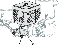
-
Remove the screws that secure the heat shield to the muffler, and remove the heat shield (Figure 84).
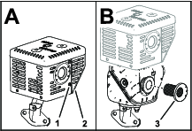
-
Remove the spark arrester screen and clean it (Figure 84).
-
Assemble the spark arrester screen to the muffler (Figure 84).
-
Assemble the heat shield to the muffler with the screws that you removed in step 2.
-
Align the muffler and a new exhaust gasket to the exhaust-outlet flange of the engine (Figure 83).
-
Assemble the muffler and gasket to the engine with the 2 flange-head bolts that you removed in step 1.
-
Torque the flange-head bolts to 35 N∙m (310 in-lb).
Fuel System Maintenance
Draining the Fuel System
-
Close the fuel-shutoff valve; refer to Opening and Closing the Fuel Shutoff Valve.
-
Locate the drain bolt that is in the side port of the carburetor bowl (Figure 85).
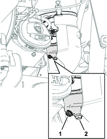
-
Align the equipment that you will use to collect the fuel beneath the drain screw.
-
Remove the drain screw from the carburetor and allow the fuel to drain from the fuel tank and the carburetor.
Note: Do not remove the bowl-retaining screw from carburetor.
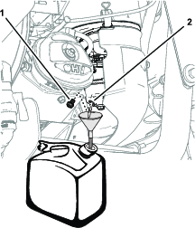
-
Install the drain bolt into the side port of the carburetor.
-
Open the fuel shutoff valve and check for leaks.
Note: Repair all fuel leaks before operating the engine.
Electrical System Maintenance
Servicing the Battery
| Maintenance Service Interval | Maintenance Procedure |
|---|---|
| Monthly |
|
Always keep the battery clean and fully charged. Use a paper towel to clean the battery case. If the battery terminals are corroded, clean them with a solution of 4 parts water and 1 part baking soda. Apply a light coating of grease to the battery terminals to prevent corrosion.
Voltage: 12 V
Danger
Charging or jump starting the battery may produce explosive gases. Battery gases can explode causing serious injury.
-
Keep sparks, flames, or cigarettes away from battery.
-
Ventilate when charging or using battery in an enclosed space.
-
Ensure that the venting path of battery is always open once the battery is filled with acid.
-
Do not lean over the batteries.
-
Always shield eyes and face from battery.
Danger
Battery electrolyte contains sulfuric acid, which is poisonous and can cause severe burns. Swallowing electrolyte can be fatal or if it touches skin can cause severe burns.
-
Wear eye protection to shield your eyes and rubber gloves to protect your skin and clothing when handling electrolyte.
-
Do not swallow electrolyte.
-
In the event of an accident, flush with water and call a doctor immediately.
Checking the Battery Charge
Caution
If the ignition is in the ON position, there is potential for sparks and for engine components to move. Sparks could cause an explosion or moving parts could accidentally engage, causing personal injury.
Ensure that the ignition switch is in the OFF position before charging the battery.
-
Prepare the machine for maintenance; refer to Preparing the Machine.
-
Remove the free end of the battery strap from the buckle and remove the battery cover from the battery box (Figure 87).
-
Measure the voltage of the battery with a voltmeter.
-
Use the table below to locate the charge state or the battery, and if needed, the battery-charger setting and charging interval recommended to charge the battery to 12.6 V or greater; refer to the battery charge table below.
Important: Ensure that the negative battery cable is disconnected, and the battery charger used for charging the battery has an output of 16 V and 7 A or less to avoid damaging the battery (see chart for recommended charger settings).
Battery Charge Table
Voltage Reading Percent Charge Maximum Charger Settings Charging Interval 12.6 or greater 100% 16 V/7 A No Charging Required 12.4 to 12.6 75 to 100% 16 V/7 A 30 Minutes 12.2 to 12.4 50 to 75% 16 V/7 A 1 Hour 12.0 to 12.2 25 to 50% 14.4 V/4 A 2 Hours 11.7 to 12.0 0 to 25% 14.4 V/4 A 3 Hours 11.7 or less 0% 14.4 V/2 A 6 Hours or More -
If the positive cable is also disconnected, connect the positive (red) cable to the positive battery terminal and slip terminal cover over the positive terminal (Figure 87).
-
Remove the screw, washer, and ground cable from the engine. Secure the battery cable to the battery terminal with the bolt, washer, and nut and torque the nut and bolt to 1978 to 2542 N∙cm (175 to 225 in-lb).
Note: If time does not permit charging the battery or if charging equipment is not available, connect the negative battery cables and run the vehicle continuously for 20 to 30 minutes to charge the battery.
-
Align the battery cover to the battery box and secure the cover and box to the battery tray with the battery strap (Figure 87).
Charging the Battery
Warning
Charging the battery produces gasses that can explode.
Never smoke near the battery and keep sparks and flames away from battery.
Important: Always keep the battery fully charged (1.265 specific gravity) to prevent battery damage when the temperature is below 32°F (0°C).
-
Remove the battery from the chassis; refer to Removing the Battery.
-
Check the electrolyte level.
-
Ensure that the filler caps are installed on the battery.
-
Charge the battery for 1 hour at 25 to 30 A or 6 hours at 4 to 6 A.
-
When the battery is fully charged, unplug the charger from the electrical outlet, and disconnect the charger leads from the battery posts (Figure 88).
-
Install the battery onto the machine and connect the battery cables; refer to Installing the Battery.
Note: Do not run the machine with the battery disconnected; electrical damage may occur.
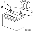
Removing and Installing the Battery
Removing the Battery
Warning
Battery terminals or metal tools could short against metal machine components, causing sparks. Sparks can cause the battery gasses to explode, resulting in personal injury.
-
When removing or installing the battery, do not allow the battery terminals to touch any metal parts of the machine.
-
Do not allow metal tools to short between the battery terminals and metal parts of the machine.
Warning
Incorrect battery-cable routing could damage the machine and cables causing sparks. Sparks can cause the battery gasses to explode, resulting in personal injury.
-
Always disconnect the negative battery cable (black) before disconnecting the positive (red) cable.
-
Always connect the positive battery cable (red) before connecting the negative (black) cable.
-
Prepare the machine for maintenance; refer to Preparing the Machine.
-
Remove the battery cover (Figure 87); refer to step 2 of Checking the Battery Charge.
-
Remove the hex-flanged bolt and flanged nut from the negative battery cable and negative (-) battery terminal, and remove the cable from the battery (Figure 89).
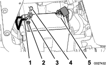
-
Slide the red-terminal cover off the positive battery terminal (Figure 89).
-
Remove the hex-flanged bolt and flanged nut from the positive (red) battery cable and the positive (+) battery terminal, and remove the cable from the battery (Figure 89).
-
Remove the battery and battery box from the battery tray of the machine.
Installing the Battery
-
Place the battery into the battery box.
-
Position the battery and battery box onto the battery tray of the machine.
-
Install the positive (red) battery cable to positive (+) battery terminal with a flanged bolt and flanged nut (Figure 89).
-
Slide the red terminal cover over the positive battery terminal.
-
Install the negative battery cable to the negative (-) battery terminal with a flanged bolt and flanged nut (Figure 89).
-
Align the battery cover to the battery box and secure the cover and box to the battery tray with the battery strap (Figure 87).
Jump-Starting the Machine
Danger
Jump-starting a battery that is cracked, frozen, has low electrolyte level, or an open/shorted battery cell can cause an explosion, resulting in serious personal injury.
Do not jump-start a battery if these conditions exist; replace the battery.
Caution
Corrosion or loose connections can cause unwanted electrical voltage spikes at any time during the jump-starting procedure.
Do not attempt to jump start a machine with loose or corroded battery terminals, or damage to the engine can occur.
Caution
Connecting the jumper cables incorrectly can immediately damage the electrical system.
Be certain of the battery-terminal polarity and the jumper-cable polarity when connecting to the battery.
Important: Be sure that the vehicles do not touch and that both electrical systems are off and at the same rated system voltage. These instructions are for negative-ground systems only.
Important: Use the properly sized jumper cables (4 to 6 AWG) with short lengths to reduce the voltage drop between systems. Ensure that the cables are color coded or labeled for the correct polarity.
-
Check the battery terminals of the discharged battery and the booster battery for corrosion (white, green, or blue “snow”).
Note: Clean the corrosion from the battery terminals prior to jump starting. Tighten the battery cable connections as necessary.
-
Ensure that the booster is a 12 V battery with a sufficient amp rating that is in good condition and fully charged.
Note: Ensure that the vent caps are tight and level. If available, place a damp cloth over any vent caps on both batteries.
-
Connect the positive (+) cable clamp (red) to the positive (+) terminal of the discharged battery ().
Note: The positive battery cable is wired to the starter or solenoid.
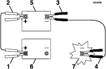
-
Connect the other positive (+) cable clamp (red) to the positive terminal of the booster battery.
-
Connect the negative (–) cable clamp (black) to the negative terminal of the booster battery.
-
Connect the other negative (–) cable clamp (black) to the engine block of the stalled machine and away from the discharged battery.
Important: Do not connect the negative (–) cable clamp (black) to the negative battery post of the discharged battery.
-
Stand away from the discharged battery of the machine.
-
Start the machine and remove the cables in the reverse order of connection, disconnect the engine block connection first.
Servicing the Fuses
The electrical system is protected by fuses, and requires no maintenance. If a fuse blows, check the component or circuit for a malfunction or short.
-
Remove the negative battery cable from the battery terminal; refer to steps 2 and 3 of Removing the Battery.
Note: Ensure that the negative battery cable does not touch the battery terminal.
-
Push the latch on the fuse/relay holder and separate the cover from the holder (Figure 91).
-
Pull the fuse from the socket of the fuse/relay holder (Figure 91).

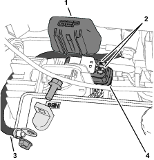
-
Install a fuse (20 A) of the same type into the socket of the fuse/relay holder (Figure 91).
-
Install the cover onto the fuse/relay holder until the cover latches securely (Figure 91).
-
Install the negative battery cable to the battery terminal, and install the battery cover; refer to steps 5 and 6 of Installing the Battery.
Drive System Maintenance
Checking the Air Pressure in the Tires
| Maintenance Service Interval | Maintenance Procedure |
|---|---|
| Every 50 hours |
|
Note: Service the air pressure in both the front and rear tires.
-
Prepare the machine for maintenance; refer to Preparing the Machine.
-
Check tire pressure in front and rear tires.
-
If necessary, adjust the air pressure in the tires to 83 to 97 kPa (12 to 14 psi).
Torqueing the Axle Bolts and Lug Nuts
| Maintenance Service Interval | Maintenance Procedure |
|---|---|
| Yearly |
|
-
Torque the axle bolts (Figure 92) of the front and rear wheels to 43 to 52 N∙m (32 to 38 ft-lb).
-
In an alternating pattern, torque the 4 wheel nuts (Figure 92) of the rear wheels to 104 to 129 N∙m (77 to 95 ft-lb).
Important: If you remove the axle bolt(s) during wheel maintenance, apply medium-grade thread-locking compound to the threads of the bolt(s) before installing the wheel(s)
Important: Do not use anti-seize compound on the wheel nuts.
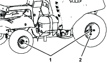
Aligning the Front Wheels
Operator supplied equipment: 2 bolts 9 x 76 mm (5/16 x 3 inch) or longer
-
Prepare the machine for maintenance; refer to Preparing the Machine.
-
Check the tire pressure; refer to Checking the Air Pressure in the Tires.
-
Center and secure the steering control by aligning 2 bolts (5/16 x 3 inch) through the outside holes on the steering control and through the control column.
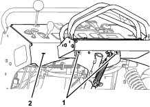
-
Measure the distance between the 2 front faces of the front tires as shown in Figure 94.
Record the front measurement here .
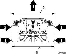
-
Measure the distance between the 2 rear faces of the front tires as shown in Figure 94.
Record the front measurement here .
Note: The front measurement should be 6.4 to 12.7 mm (1/4 to 1/2 inch) larger than the rear measurement.
-
If the front measurement is smaller than 6.4 mm (1/4 inch) or larger than 12.7 mm (1/2 inch), adjustment the rod ends for the steering linkage as follows:
-
Remove the 4 thumb screws that secure the front cover (below the impeller) to the chassis and remove the cover (Figure 95).
-
Loosen the jam nuts at the rod ends.
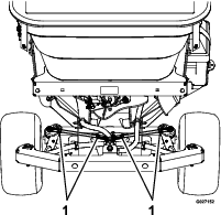
-
Rotate the steering rod to lengthen or shorten the linkage. Adjust both the left and right steering linkages equally.
Note: The factory center-to-center distance between the ball-joint rod ends at the steering linkage is 23.3 cm (9.21 inches).
-
Tighten the jam nuts.
-
Align the holes in the front cover with the clip nuts in the chassis and secure the cover with the 4 thumb nuts that you removed in 1.
-
-
Remove the bolts that you installed in step 3 from the control column and steering control.
Servicing the Transaxle
| Maintenance Service Interval | Maintenance Procedure |
|---|---|
| Every 50 hours |
|
Transaxle Oil Type: Toro® HYPR-OIL™ 500 hydraulic oil or Mobil® 1 15W-50
-
Prepare the machine for maintenance; refer to Preparing the Machine.
-
Rotate counterclockwise the 2 quarter-turn fasteners that secure the knee pad to the chassis of the machine (Figure 97).
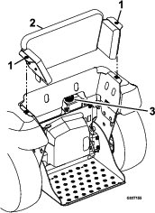
-
Lift the knee pad up and rearward slightly and remove the pad from the machine (Figure 97).
-
Clean area around fluid-expansion tank and remove cap (Figure 97).
-
Check the fluid level in the expansion tank.
Note: The fluid-level cover the bottom port in tank.
-
If the fluid level is too low, add the specified fluid into the expansion tank.
-
Install the tank cap onto the expansion tank and tighten the cap until it is snug (Figure 97).
Note: Do not overtighten the cap.
Controls System Maintenance
Adjusting the Pattern Control Cable for the Spreader
-
Prepare the machine for maintenance; refer to Preparing the Machine.
-
Empty the hopper; refer to Emptying the Spreader.
-
Close the impeller gate by pushing the heavy distribution granular-gate lever forward fully (Figure 98).
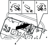
-
Rotate the spread-pattern-control handle counterclockwise, push the handle down, and rotate the spread-pattern-control handle clockwise(3) refer to Figure 98.
-
Loosen the jam nut at the end of the pattern-control cable (Figure 99).
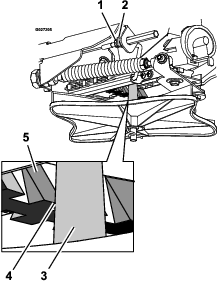
-
Pull the linkage rod until there is 1/8 inch (3.2 mm) gap between the ramp tooth and the impeller shaft (Figure 99).
-
Tighten the jam nut (Figure 99).
-
Adjust the spread-pattern-control handle; refer to Adjusting the Spreader Pattern.
Maintaining the Chassis
Checking the Machine for Loose Hardware
| Maintenance Service Interval | Maintenance Procedure |
|---|---|
| Before each use or daily |
|
-
Prepare the machine for maintenance; refer to Preparing the Machine.
-
Visually inspect machine for damaged or worn parts, and check for loose hardware.
Note: Before operating the machine, replace any damaged parts and tighten all loose hardware.
Maintaining the Sprayer System
Checking Sprayer System
| Maintenance Service Interval | Maintenance Procedure |
|---|---|
| Every 50 hours |
|
-
Prepare the machine for maintenance; refer to Preparing the Machine.
-
Check all hoses, nozzles, and fittings for damage and leaks.
Note: Replace all damaged or leaking sprayer components.
-
Check the nozzle strainers and in-line strainers for accumulation of dirt and chemical sludge.
Note: Clean or replace strainers with an accumulation of dirt and chemical sludge.
Cleaning
Cleaning the Engine and the Exhaust System Area
| Maintenance Service Interval | Maintenance Procedure |
|---|---|
| After each use |
|
Caution
Excessive debris around engine-air intake and exhaust system area can cause engine, exhaust area, and hydraulic system to overheat which can create a fire hazard.
Clean all debris from engine and exhaust system area.
-
Prepare the machine for maintenance; refer to Preparing the Machine.
-
Clean all debris from screen next to the starter grip of the engine, around engine shrouding, fuel tank, and exhaust system area.
-
Wipe up any excessive grease or oil around the engine and exhaust system area.
-
Clean muffler-heat shields of all debris, dirt, and oil.
Cleaning the Debris from the Machine
| Maintenance Service Interval | Maintenance Procedure |
|---|---|
| After each use |
|
-
Prepare the machine for maintenance; refer to Preparing the Machine.
-
Clean off any debris or chemical build-up on the machine, especially the nozzles, sprayer-tank opening, impeller, and the spray wand and its holder.
Removing the Engine Shroud and Cleaning the Cooling Fins
| Maintenance Service Interval | Maintenance Procedure |
|---|---|
| Every 80 hours |
|
-
Prepare the machine for maintenance; refer to Preparing the Machine.
-
Remove cooling shroud from engine.
-
Clean cooling fins of the engine.
Note: Also, clean dust, dirt, and oil from external surfaces of engine which can cause improper cooling.
-
Install the cooling shrouds onto the engine.
Note: Operating the engine without cooling shrouds will cause engine damage due to overheating.
Waste Disposal
Chemical Disposal
Improper chemical disposal can pollute the environment and cause health issues.
Follow the disposal directions on the chemical-manufacturer’s label. Dispose of chemicals and containers in accordance to local/state/federal laws.
Disposing of the Engine Oil
Engine oil and hydraulic fluid are both pollutants to the environment. Dispose of used pollutants at a certified-recycling center or according to your state and local regulations.
Disposing of the Battery
Danger
Battery electrolyte contains sulfuric acid, which is poisonous and can cause severe burns. Swallowing electrolyte can be fatal or if it touches skin can cause severe burns.
-
Wear eye protection to shield eyes, and rubber gloves to protect skin and clothing when handling electrolyte.
-
Do not swallow electrolyte.
-
In the event of an accident, flush with water and call a doctor immediately.
Federal law states that batteries should not be placed in the garbage. Management and disposal practices for batteries must follow relevant federal, state, or local laws.
Take the battery to a local certified-recycling center if you replace a worn or damaged battery or if the machine no longer operates and is being scrapped.
Note: If no local recycling is available, return the battery to any certified battery seller.
Storage
-
Set sprayer-pump switch to the OFF position, stop the machine, move motion-control lever to the NEUTRAL position, shut off the engine, wait for all moving parts to stop, remove key, and engage parking brake.
-
Remove dirt and grime from the entire machine.
Important: Do not use brackish or reclaimed water to clean the machine.
Important: You can wash the machine with mild detergent and water. Do not pressure wash the machine. Avoid excessive use of water, especially near the engine and hydrostatic drive.
-
Service the air cleaner; refer to Servicing the Air Cleaner.
-
Lubricate the machine; refer to Lubricating the Grease Fittings.
-
Change the engine oil; refer to Changing the Engine Oil.
-
Check and tighten all bolts, nuts, and screws. Repair or replace any part that is damaged.
-
Paint all scratched or bare metal surfaces. Paint is available from your Authorized Service Dealer.
-
Store the machine in a clean, dry garage or storage area.
-
Cover the machine to protect it and keep it clean.
Preparing the Machine for Extended or Winter Storage
To help protect the pumps from freezing temperatures, ensure that the machine is free of all caustic chemicals and residue.
Cleaning the Spreader
Perform all the steps in Cleaning and Lubricating the Spreader.
Winterizing the Sprayer
Emptying the Tank
-
Perform all the steps in Cleaning the Sprayer System and Wand, Cleaning the Strainer, and Cleaning the Sprayer Nozzle.
-
Empty the sprayer system by performing the following:
-
Empty the sprayer tank; refer to Emptying the Sprayer Tank.
-
Start the machine and set sprayer-pump switch to the ON position
-
Push the tank-agitation lever to the OFF position.
-
Pull the narrow-spray pattern lever.
Note: Run the sprayer nozzle until the narrow nozzle is spraying air.
-
Push the narrow-spray pattern lever and pull back the wide-spray pattern lever.
Note: Run the sprayer nozzles until the both wide nozzles are spraying air.
-
Push forward the wide-spray pattern lever.
-
-
Shut off the sprayer pump and the engine.
Preparing the Sprayer System
Antifreeze type: 2.5 L (0.7 US gallon) rust inhibiting, non-alcohol based, RV-antifreeze concentrate
Important: Do not allow all the antifreeze mixture to empty from the sprayer tank while running the sprayer nozzles and wand. Keeping some of the antifreeze in the pump, valves, and hoses will help prevent corrosion and damage caused by moist air trapped in the sprayer system.Do not use brackish or reclaimed water in the spray system.
-
Mix 2.5 L (0.7 US gallon) RV anti-freeze concentrate with 5.1 L (1.3 US gallon) water and pour the antifreeze mixture into the into the sprayer tank.
Note: Use a rust inhibiting, non-alcohol based, RV antifreeze concentrate.
-
Start the machine and set the sprayer-pump switch to the ON position.
-
Pull back the narrow-spray pattern lever to the ON position.
Note: Allow the antifreeze to circulate through sprayer and nozzle.
-
Push forward the narrow-spray pattern lever and pull back the wide-spray pattern lever.
Note: Allow the antifreeze to circulate through sprayer and nozzle.
-
Push forward the wide-spray pattern lever.
-
Remove the wand from its holder, point it in a safe direction, and squeeze the spray-wand trigger.
Note: Allow the antifreeze to circulate through sprayer and nozzle and then return the wand to its holder.
-
Set the sprayer-pump switch to the OFF position and shut off the engine.
Troubleshooting
Important: Ensure that the operator safety mechanisms for the machine are connected and in proper operating condition before you use the machine.
When a problem occurs, do not overlook the simple causes. For example, starting problems could be caused by an empty fuel tank.
The following table lists some of the common causes of trouble. Do not attempt to service or replace major engine items or any items that call for special timing of adjustments procedures (such as valves, governor, etc.). Have this work done by your engine service dealer.
Note: When disconnecting electrical connectors, do not pull on the wires to separate the connectors.
Spreader Fault Codes
|
Motor Overcurrent !02 The motor overcurrent fault code !02 displays if the motor load circuit draws too much current. Check the motor and inspect it for damage and wear. | 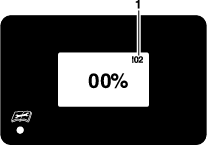 |
|
1. Fault code !02 (motor overcurrent) |
|
|
Voltage Measurement !04 The voltage measurement fault code !05 displays if the sprayer controller cannot sense motor feedback voltage. Check the wire from pin 18 (MOTOR IN) of the controller connector. | 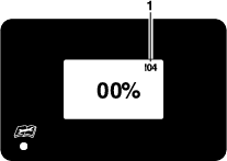 |
|
1. Fault code !04 (voltage measurement) |
|
|
Motor Wire !05 The motor wire fault code !05 displays if the sprayer controller cannot sense the load circuits (OUT 1 or OUT 2) between the sprayer and information display and the motor.
Check that pin 6 (MOTOR OUT 1) and pin 8 (MOTOR OUT 2) are seated and locked in the controller connector. | 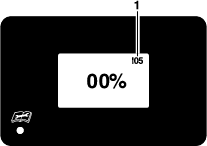 |
|
1. Fault code !05 (motor wire) |
|
|
Motor Open !06 The motor open fault code !06 displays if the spreader controller cannot sense the motor signal circuit (MOTOR IN).
| 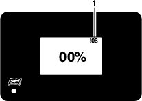 |
|
1. Fault code !06 (motor open) |
Sprayer Fault Codes
|
Voltage The voltage fault code displays if the key-run voltage is less than 12.5 V or greater than 16 V.
| |
|
Voltage fault code |
|
|
Motor Overcurrent !02 The motor overcurrent fault code !02 displays if the motor load circuit draws too much current. Check the motor and inspect it for damage and wear.
Check that pin 6 (MOTOR OUT 1) and pin 8 (MOTOR OUT 2) are seated and locked in the controller connector. | 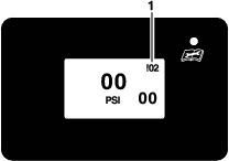 |
|
1. Fault code !02 (motor overcurrent) |
|
|
Motor Wire !05 The motor wire fault code !05 displays if the sprayer controller cannot sense the load circuits (OUT 1 or OUT 2) between the sprayer and information display and the motor.
| 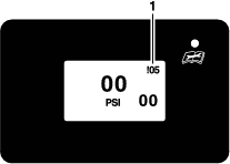 |
|
1. Fault code !05 (motor wire) |
|
|
Motor Open !06 The motor open fault code !06 displays if the sprayer controller cannot sense the motor signal circuit (MOTOR IN).
| 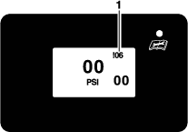 |
|
1. Fault code !06 (motor open) |
| Problem | Possible Cause | Corrective Action |
|---|---|---|
| The spreader information display or sprayer information display shows fault core !02. |
|
|
| The spreader information display shows fault core !04. |
|
|
| The spreader information display or sprayer information display shows fault core !05. |
|
|
| The spreader information display or sprayer information display shows fault core !06. |
|
|
| The spreader controller or the sprayer controller does not power. |
|
|
| The spreader controller or the sprayer controller shuts off intermittently. |
|
|
| The spreader controller or the sprayer controller is unresponsive. |
|
|
| Sprayer and information display shows the low battery voltage icon displays a quarter of the time. |
|
|
| The recirculation pump shuts off. |
|
|
| Problem | Possible Cause | Corrective Action |
|---|---|---|
| The starter does not rotate the engine. |
|
|
| The engine does not start, it starts hard, or it fails to keep running. |
|
|
| The engine loses power. |
|
|
| The engine overheats. |
|
|
| The machine pulls to the left or the right (with steering control fully forward). |
|
|
| The machine does not drive. |
|
|
| The machine vibrates abnormally. |
|
|
| The impeller does not rotate. |
|
|
| The spreader or sprayer pattern is uneven. |
|
|
| There is no spray from the sprayer nozzles in the boom or the nozzles have poor output. |
|
|
| No material dispensed from hopper. |
|
|
| The spray wand does not work. |
|
|
Schematics
Electrical Schematic 135-6127
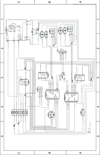
Sprayer System Schematic