Installation
Preparing the Machine
-
Park the machine on a level surface.
-
Disengage the blade-control switch.
-
Move the motion-control levers outward to the NEUTRAL-LOCK position to engage the parking brake.
-
Shut off the engine and remove the key.
Removing the Guards
Note: Retain all removed parts for later installation.
-
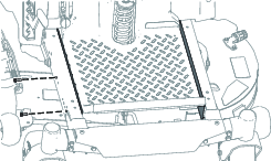
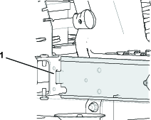
Remove the bolts securing the guards on the sides of the frame.
-
Remove the guards on both sides of the frame (Figure 1).
Installing the Weights
Parts needed for this procedure:
| Bolt (3/8 x 1 inch) | 4 |
| Locknut (3/8 inch) | 6 |
| Left weight-mounting bracket | 1 |
| Right weight-mounting bracket | 1 |
| Washer | 2 |
| Bolt (5/8 x 2-3/4 inches) | 2 |
| Suitcase weight | 8 |
Caution
The bagger changes the weight distribution of the machine. Operating the machine without the front weights may cause an unstable condition, which could result in a loss of control.
Ensure the front weights are properly installed before operating the machine with the bagger attachment.
-
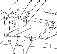
Install the weight-mounting brackets to the under side of the frame using 2 bolts (3/8 x 1 inch), and 2 locknuts (3/8 inch) as shown in Figure 2.
-
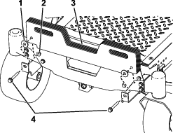
Install suitcase weights to the weight mounting brackets using 2 bolts (5/8 x 2-3/4 inches), 2 washers, and 2 locknuts (3/8 inch) as follows:
-
If your machine has a 42-inch stamped deck, install 8 suitcase weights.
-
If your machine has any other cutting deck, install 6 suitcase weights (Figure 3).
-
-
Once you have installed all the weights and brackets, ensure that all the fasteners are tight. Tighten as necessary.
Important: Whenever you remove the bagger attachment, remember to remove the front weights to return the proper stability to the machine.
Installing the Guards
-
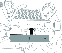
Insert the top of the guard under the deck; tilt the guard so that it slides under the frame and fit the guard into the notches (Figure 4).
-
Secure the guards to the frame using the bolts removed in Removing the Guards as shown in Figure 1.