Installation
Note: Determine the left and right sides of the machine from the normal operating position.
Preparing the Machine
For Gasoline GTX Vehicles
-
Park the machine on a level surface, set the parking brake, shut off the engine, and remove the key.
-
Disconnect the negative-battery cable; refer to your Operator’s Manual.
For Electric GTX Vehicles
-
Park the machine on a level surface, set the parking brake, shut off the machine, and remove the key.
-
Disconnect the main negative-battery cable (black) that connects the bank of batteries to the ground point of the machine; refer to your Operator’s Manual.
Installing and Connecting the Horn
Parts needed for this procedure:
| 12 V horn assembly (for Gasoline GTX vehicles) | 1 |
| 48 V horn assembly (for Electric GTX vehicles) | 1 |
| Hex-head screw (5/16 x 3/4 inch) | 1 |
| Flange nut (5/16 inch) | 1 |
For Gasoline GTX Vehicles
-
Release the rubber straps on both sides of the hood and raise the hood.
-
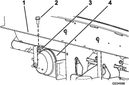
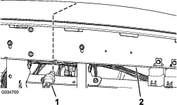
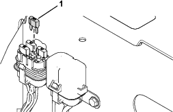
Install the 12 V horn assembly to the existing hole in the dash bracket with the hex-head screw (5/16 x 3/4 inch) and flange nut (5/16 inch) as shown in Figure 1.
-
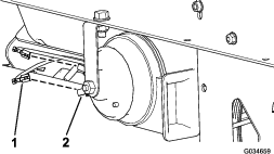
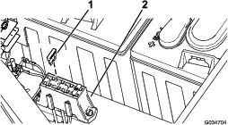
Plug the 2 female connectors from the main wire harness into the 2 male connectors on the 12 V horn (Figure 2).
For Electric GTX Vehicles
-
Release the rubber straps on both sides of the hood and raise the hood.
-
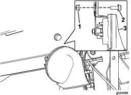
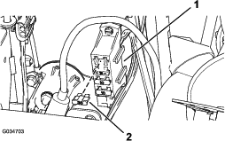
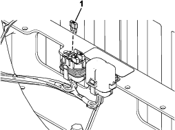
Install the 48 V horn assembly to the existing hole in the dash bracket with the hex-head screw (5/16 x 3/4 inch) and flange nut (5/16 inch) as shown in Figure 3.
Note: The bracket on the horn assembly and the flange nut (5/16 inch) are located on the inside of the dash bracket (Figure 3).
-
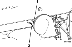
Plug the 2 female connectors from the main wire harness into the 2 male connectors on the 48 V horn (Figure 4).
Installing and Connecting the Horn Switch
Parts needed for this procedure:
| Horn switch | 1 |
| Rubber button | 1 |
For Gasoline GTX Vehicles
-
Reach under the dash bracket and push the existing plastic plug out.
-
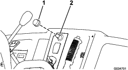
Reach under the dash bracket and install the horn switch into the opening (Figure 5).
-
Install the rubber button to the horn switch (Figure 6).
-
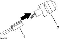
Plug the female connector from the main wire harness to the male connector on the horn switch (Figure 7).
For Electric GTX Vehicles
-
Reach under the dash bracket and push the existing plastic plug out.
-
Reach under the dash bracket and install the horn switch into the opening (Figure 5).
-
Install the rubber button to the horn switch (Figure 6).
-
Plug the female connector from the main wire harness to the male connector on the horn switch (Figure 7).
Installing the Fuse
Parts needed for this procedure:
| Fuse (30 A) | 1 |
For Gasoline GTX Vehicles
Connecting the Battery
For Gasoline GTX Vehicles
Connect the negative-battery cable; refer to your Operator’s Manual.
For Electric GTX Vehicles
Connect the main negative-battery cable (black) that connects the bank of batteries to the ground point of the machine; refer to your Operator’s Manual.
Testing the Horn Function
Confirm that the horn sounds when you press the horn button and stops when you release it.
Note: If the horn does not sound, ensure that the wire-harness connectors are secure.