Safety
Rollover Protection System (ROPS) Safety
-
The ROPS is an integral safety device. Do not remove any of the ROPS components from the machine.
-
Ensure that the seat belt is attached and that you can release it quickly in an emergency.
-
Keep the roll bar in the fully raised and locked position and always wear your seat belt whenever the roll bar is up.
-
Check carefully for overhead objects before you drive under them, and do not contact them.
-
Replace damaged ROPS components. Do not repair or alter them.
-
There is no rollover protection when the roll bar is down.
-
Wheels dropping over edges, over steep banks, or into water can cause a rollover, which may result in serious injury or death.
-
Do not wear the seat belt when the roll bar is down.
-
Lower the roll bar only when absolutely necessary; raise it as soon as clearance permits.
-
In the event of a rollover, take the machine to an Authorized Service Dealer to inspect the ROPS.
-
Use only Toro approved accessories and attachments for the ROPS.
Installation
Determine the left and right sides of the machine from the normal operating position.
Preparing the Machine
-
Park the machine on a level surface.
-
Disengage the PTO, engage the parking brake, and move the motion-control levers outward to the NEUTRAL-LOCK position.
-
Shut off the engine and remove the key.
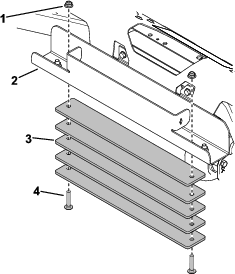
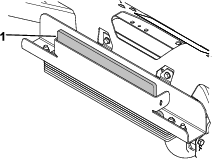
Installing the Weights
Parts needed for this procedure:
| Weight | 5 |
| Plate | 1 |
| Carriage bolt (3/8 x 2 inches) | 2 |
| Nut (3/8 inch) | 2 |
Installing the Lower Tubes and Seat Belt
Parts needed for this procedure:
| Left lower roll bar | 1 |
| Right lower roll bar | 1 |
| Bolt (1/2 x 4 inches) | 4 |
| Washer | 6 |
| Locknut (1/2 inch) | 6 |
| Left support bracket | 1 |
| Right support bracket | 1 |
| Bolt (1/2 x 1-1/4 inches) | 2 |
| Bolt (1/2 x 1-3/4 inches) | 2 |
Note: The engine and left and right pods are not shown in the figures.
-
Raise and support the machine so that the rear wheels are off the ground.
-
Remove the rear wheels.
-
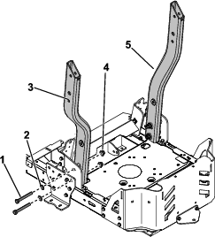
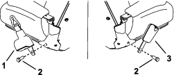
Loosely install the left and right lower roll bar tubes using 2 bolts (1/2 x 4 inches), 2 washers, and 2 locknuts (1/2 inch) for each tube (Figure 4).
Note: Ensure that the battery cables route between the right pod and the right roll bar.
-
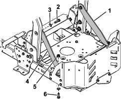
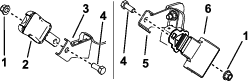
Loosely install the left and right support brackets using 1 bolt (1/2 x 1-1/4 inches), 1 locknut (1/2 inch), 1 bolt (1/2 x 1-3/4 inches), and 1 washer for each bracket (Figure 5).
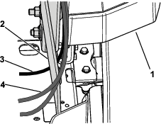
Note: Ensure that the battery ground cable routes under the right support bracket and other cables route above the right support bracket (Figure 6).
Installing the Seat Belt
Parts needed for this procedure:
| Left seat-belt bracket (machines without MyRide only) | 1 |
| Right seat-belt bracket (machines without MyRide only) | 1 |
| Seat-belt assembly | 1 |
| Seat-belt buckle | 1 |
| Bolt (1/2 x 1-1/4 inches) | 4 |
| Locknut (1/2 inch) | 4 |
| Self-tapping screw (1/4 x 5/8 inch) | 2 |
Machines without MyRide
-
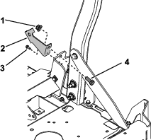
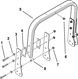
Install the left and right seat-belt brackets using 1 bolt (1/2 x 1-1/4 inches), 1 locknut (1/2 inch), and 1 self-tapping screw (1/4 x 5/8 inch) for each bracket (Figure 7). Torque the bolts to 41 N∙m (30 ft-lb).
-
Install the seat-belt assembly and buckle to the brackets using 2 bolts (1/2 x 1-1/4 inches) and 2 locknuts (1/2 inch) as shown in Figure 8. Torque the bolts to 41 N∙m (30 ft-lb).
Machines with MyRide
Install the seat-belt assembly and buckle to the seat using 2 bolts (1/2 x 1-1/4 inches) as shown in Figure 9.
Installing the Roll Bar
Parts needed for this procedure:
| Roll bar | 1 |
| Side plate | 4 |
| Bolt (1/2 x 3 inches) | 8 |
| Flat spacer | 4 |
| Washer | 6 |
| Locknut (1/2 inch) | 8 |
| Bumper | 3 |
| Cylindrical spacer | 4 |
| Lanyard with pivot pin, washer, and hairpin cotter | 1 |
Note: Leave the bolts loose enough so that the parts are free to shift around.
-
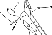
Install 2 side plates to both sides of the roll bar using 3 bolts (1/2 x 3 inches), 2 flat spacers, 3 washers, 1 cylindrical spacer, and 3 locknuts (1/2 inch) on each side (Figure 10).
-
Install a bumper in the center of the roll bar (Figure 10).
-
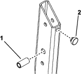
Install a bumper and cylindrical spacer to both lower roll bar tubes (Figure 11).
-
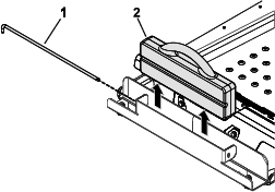
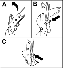
With the assistance of a second person, attach the roll bar assembly and the lanyard washer to the lower roll bar tubes using a bolt (1/2 x 3 inches) and locknut (1/2 inch) on each tube (Figure 12).
-
Raise the roll bar into the upright position and lock it into place using the pivot pin and hairpin cotter on both sides of the roll bar (Figure 13).
-
Torque all 1/2-inch bolts to 95 N∙m (70 ft-lb).
-
Install the rear tires. Torque the lug nuts to 95 to 122 N∙m (70 to 90 ft-lb).
-
Lower the machine to the ground.
Operation
Using the Rollover-Protection System
Warning
To avoid injury or death from rollover: keep the roll bar in the fully raised, locked position and use the seat belt.
Ensure that the seat is secured to the machine.
Warning
There is no rollover protection when the roll bar is in the down position.
-
Lower the roll bar only when absolutely necessary.
-
Do not wear the seat belt when the roll bar is in the down position.
-
Drive slowly and carefully.
-
Raise the roll bar as soon as clearance permits.
-
Check carefully for overhead clearances (i.e., branches, doorways, electrical wires) before driving under any objects, and do not contact them.
Important: Ensure that the seat is secured to the machine.
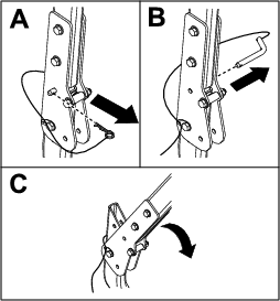
Raising the Roll Bar
Lowering the Roll Bar