Note: Determine the left and right sides of the machine from the normal operating position.
Installation
Preparing the Machine
-
Park the machine on a level surface, disengage the PTO, and engage the parking brake.
-
Shut off the engine, remove the key, and wait for all moving parts to stop before leaving the operating position.
-
Disconnect the battery; refer to your Operator’s Manual.
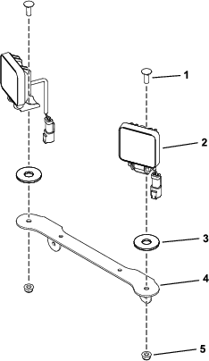
Installing the Lights
Parts needed for this procedure:
| LED light | 2 |
| Light bracket | 1 |
| Friction washer | 2 |
| Carriage bolt (5/16 x 7/8 inch) | 2 |
| Flange nut (5/16 inch) | 2 |
| Light clamp | 2 |
| Locknut (1/4 inch) | 4 |
Routing the Wire Harness
Parts needed for this procedure:
| Wire harness | 1 |
| Cable ties | 6 |
| Toggle switch | 1 |
-
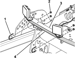
Plug the 2 connectors at the front of the machine into the LED lights (Figure 3).
-
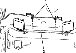
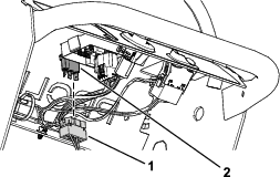
Secure the wire harness to the light bracket using the 2 push-mount fasteners on the wire harness (Figure 4).
-
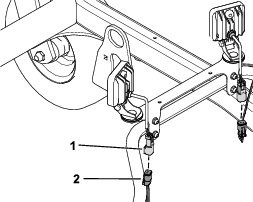
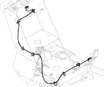
Route the wire harness along the right side of the machine as shown in Figure 5.
-
Secure the wire harness to the machine using the cable ties (Figure 5).
-
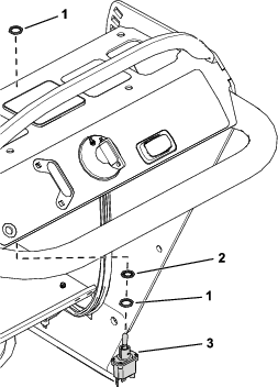
Plug the connector into the toggle-switch connector (Figure 6).
-
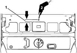
Drill a hole (12 mm or 1/2 inch) in front of the hour meter for the toggle switch (Figure 7).
-
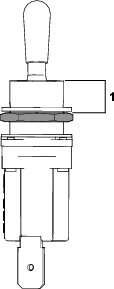
From the top of the threads on the toggle switch, set the depth of the bottom hex nut at 7.9 mm (5/16 inch) as shown in Figure 8.
-
Secure the toggle switch in the opening using the 2 hex nuts and 1 lock washer (Figure 9).
Note: Do not use the key-tab washer.
-
Connect the battery; refer to your Operator’s Manual.