| Maintenance Service Interval | Maintenance Procedure |
|---|---|
| Before each use or daily |
|
Introduction
This machine is a ride-on, reel-blade greens mower intended to be used by professional, hired operators in commercial applications. It is primarily designed for cutting grass on well-maintained turf. Using this product for purposes other than its intended use could prove dangerous to you and bystanders.
Read this information carefully to learn how to operate and maintain your product properly and to avoid injury and product damage. You are responsible for operating the product properly and safely.
Visit www.Toro.com for more information, including safety tips, training materials, accessory information, help finding a dealer, or to register your product.
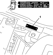
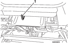
Whenever you need service, genuine Toro parts, or additional information, contact an authorized Toro distributor and have the model and serial numbers of your product ready. Figure 1 identifies the location of the model and serial numbers on the product. Write the numbers in the space provided.
Important: With your mobile device, you can scan the QR code on the serial number decal (if equipped) to access warranty, parts, and other product information.
This manual identifies potential hazards and has safety messages identified by the safety-alert symbol (Figure 2), which signals a hazard that may cause serious injury or death if you do not follow the recommended precautions.

This manual uses 2 words to highlight information. Important calls attention to special mechanical information and Note emphasizes general information worthy of special attention.
This product complies with all relevant European directives; for details, please see the separate product specific Declaration of Conformity (DOC) sheet.
It is a violation of California Public Resource Code Section 4442 or 4443 to use or operate the engine on any forest-covered, brush-covered, or grass-covered land unless the engine is equipped with a spark arrester, as defined in Section 4442, maintained in effective working order or the engine is constructed, equipped, and maintained for the prevention of fire.
The enclosed engine owner's manual is supplied for information regarding the US Environmental Protection Agency (EPA) and the California Emission Control Regulation of emission systems, maintenance, and warranty. Replacements may be ordered through the engine manufacturer.
Warning
CALIFORNIA
Proposition 65 Warning
The engine exhaust from this product contains chemicals known to the State of California to cause cancer, birth defects, or other reproductive harm.
Battery posts, terminals, and related accessories contain lead and lead compounds, chemicals known to the State of California to cause cancer and reproductive harm. Wash hands after handling.
Use of this product may cause exposure to chemicals known to the State of California to cause cancer, birth defects, or other reproductive harm.
Safety
This machine has been designed in accordance with EN ISO 5395 and ANSI B71.4-2017 and meets these standards when you complete the setup procedures.
General Safety
This product is capable of amputating hands and feet and of throwing objects.
-
Read and understand the contents of this Operator’s Manual before starting the engine.
-
Use your full attention while operating the machine. Do not engage in any activity that causes distractions; otherwise, injury or property damage may occur.
-
Do not put your hands or feet near moving components of the machine.
-
Do not operate the machine without all guards and other safety protective devices in place and working on the machine.
-
Keep clear of any discharge opening.
-
Keep children, bystanders, and pets out of the operating area. Never allow children to operate the machine.
-
Always shut off the engine, remove the key (if equipped), wait for all moving parts to stop, and allow the machine to cool before adjusting, repairing, cleaning, or storing the machine.
Improperly using or maintaining this machine can result in injury.
To reduce the potential for injury, comply with these safety instructions
and always pay attention to the safety-alert symbol  , which means Caution, Warning,
or Danger—personal safety instruction. Failure to comply with
these instructions may result in personal injury or death.
, which means Caution, Warning,
or Danger—personal safety instruction. Failure to comply with
these instructions may result in personal injury or death.
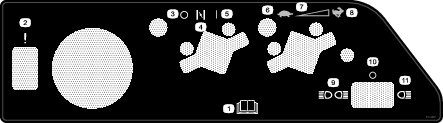
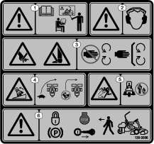
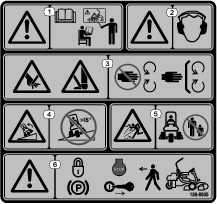
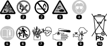
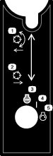
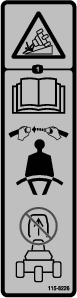
Safety and Instructional Decals
|
Safety decals and instructions are easily visible to the operator and are located near any area of potential danger. Replace any decal that is damaged or missing. |


Setup
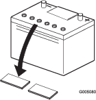
Activating and Charging the Battery
Use only electrolyte (1.265 specific gravity) to fill battery initially.
-
Remove the wing nuts, washers, and battery clamp and lift out the battery.
Important: Do not add electrolyte while the battery is in the machine. You could spill it, causing corrosion.
-
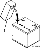
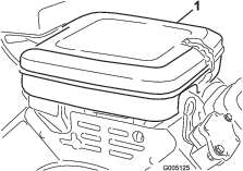
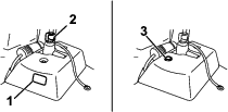
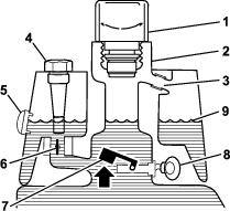
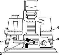
Clean the top of the battery and remove the vent caps (Figure 3).
-
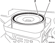
Carefully fill each cell with electrolyte until the plates are covered with about 6 mm (1/4 inch) of fluid (Figure 4).
-
Allow approximately 20 to 30 minutes for the electrolyte to soak into the plates. Fill as necessary to bring the electrolyte to within about 6 mm (1/4 inch) of the bottom of the fill well (Figure 4).
-
Connect a 2 to 4 A battery charger to the battery posts. Charge the battery for at least 2 hours at 4 A or for at least 4 hours at 2 A until the specific gravity is 1.250 or higher and the temperature is at least 16°C (60°F) with all cells gassing freely.
Warning
Charging the battery produces gasses that can explode.
Never smoke near the battery and keep sparks and flames away from the battery.
Important: If you do not charge the battery for at least the time specified above, you may reduce the life of the battery.
-
When the battery is charged, disconnect the charger from the electrical outlet and battery posts.
Note: After the battery has been activated, add only distilled water to replace normal loss, although maintenance-free batteries should not require water under normal operating conditions.
Important: Failure to correctly activate the battery may result in battery gassing and/or premature battery failure.
-
Install the vent caps.
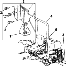
Installing the Battery
Parts needed for this procedure:
| Carriage bolt (5/16 x 3/4 inch) | 2 |
| Nut (5/16 inch) | 2 |
-
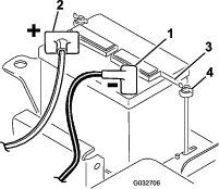
Mount the battery with the battery terminals toward the front of the machine.
-
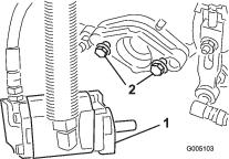
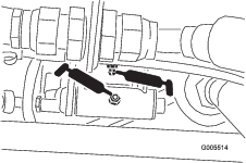
Connect the positive battery cable (red) from the starter solenoid to the positive post (+) of the battery (Figure 5). Secure it with a carriage bolt and nut.
Important: Ensure that the cable will clear the seat in the rear-most position, which could cause wear or damage to the cable.
Warning
Battery terminals or metal tools could short against metal machine components, causing sparks. Sparks can cause the battery gasses to explode, resulting in personal injury.
-
When removing or installing the battery, do not allow the battery terminals to touch any metal parts of the machine.
-
Do not allow metal tools to short between the battery terminals and metal parts of the machine.
-
-
Connect the black ground cable (from the engine base) to the negative (-) post of the battery. Secure it with a carriage bolt and nut.
Warning
Incorrect battery cable routing could damage the machine and cables, causing sparks. Sparks can cause the battery gasses to explode, resulting in personal injury.
-
Always disconnect the negative (black) battery cable before disconnecting the positive (red) cable.
-
Always connect the positive (red) battery cable before connecting the negative (black) cable.
-
-
Coat both terminals with petroleum jelly.
-
Install the battery clamp and washers and secure them with wing nuts (Figure 5).
-
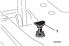
Place the terminal cover over the positive (+) battery post.
Installing the Roll Bar
Parts needed for this procedure:
| Bolt (1/2 x 1-3/4 inches) | 2 |
| Bolt (1/2 x 1-1/2 inches) | 6 |
| Nut (1/2 inch) | 8 |
-
Remove the screws and nuts supporting the jack pad on the right side of the machine.
-
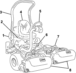
Lower the roll bar (Figure 6) onto the mounting brackets, aligning the mounting holes.
-
Secure the left side of the roll bar to the mounting bracket with 4 bolts (1/2 x 1-1/2 inches) and locknuts (Figure 6).
-
Torque the fasteners to 91 to 115 N∙m (67 to 85 ft-lb).
-
Secure the right side of the roll bar and the previously removed jack pad to the mounting bracket with 2 bolts (1/2 x 1-1/2 inches), 2 bolts (1/2 x 1-3/4 inches), and locknuts as illustrated in Figure 6.
-
Torque the fasteners to 91 to 115 N∙m (67 to 85 ft-lb).
Warning
Failure to wear the seat belt while operating the vehicle can result in you being thrown from the seat and injured during a rollover accident.
Always use the seat belt.
Installing the Cutting Units
Parts needed for this procedure:
| Cutting unit | 3 |
| Grass basket | 3 |
Important: Do not raise the suspension to the transport position when the reel motors are in the holders on the machine frame. Damage to the motors or hoses could result.
Note: When sharpening, setting the height of cut, or performing other maintenance procedures on the cutting units, store the cutting unit reel motors in the support tubes on the front of the frame and side of the machine to prevent damaging the hoses.
-
Remove the cutting units from the cartons. Assemble and adjust them as listed in the cutting unit Operator's Manual.
-
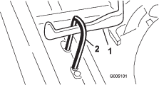
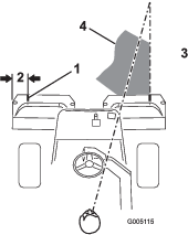
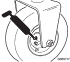
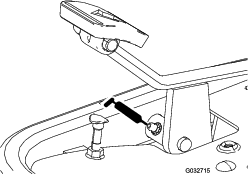
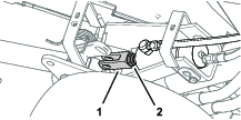
Slide the cutting unit under the pull frame while sliding the lift hook onto the lift arm (Figure 7).
-
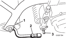
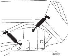
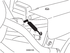
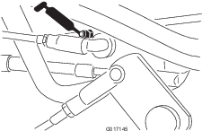
Slide the sleeve back on the ball joint receiver and hook the receiver onto the cutting unit ball stud. Release the sleeve so that it slides over the stud and locks the assemblies together (Figure 8).
-
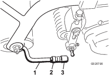
Mount the baskets on the pull frames, loosen the jam nuts on the pull arms, and adjust the ball sockets until there is 6 to 13 mm (1/4 to 1/2 inch) clearance between the lip of the basket and the reel blades.
Note: This prevents the basket from tipping the cutting unit forward, causing the lift roller to come off the lift arm while in the mowing operation.
Note: Ensure that the basket lip is equidistant from the reel blades all across each reel. If the basket is too close to the reel, it is possible for the reel to contact the basket when the cutting unit is raised off or lowered to the ground.
-
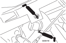
Align the sockets in the ball joints so the open side of the socket is centered toward the ball stud, and tighten the jam nuts to secure the sockets in position (Figure 9).
-
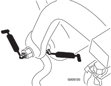
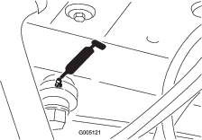
Ensure that there is approximately 13 mm (1/2 inch) of threads exposed on each reel drive motor mounting bolt (Figure 10).
-
Coat the spline shaft of the motor with clean grease.
-
Install the motor by rotating the motor clockwise so that the motor flanges clear the studs, then rotate the motor counterclockwise until the flanges encircle the studs.
-
Tighten the mounting bolts (Figure 10).
Marking the Outer Grass Baskets
To assist in aligning the machine for successive cutting passes, do the following procedure to the No. 2 and No. 3 cutting unit baskets:
-
Measure in approximately 12.7 cm (5 inches) from the outer edge of each basket.
-
Either place a strip of white tape or paint a line onto each basket paralleling the outer edge of each basket (Figure 11).
Adding the Rear Ballast and Weight Kit
Parts needed for this procedure:
| Rear Weight Kit (Part No. 100-6442)—purchase separately | 1 |
| 19.5 kg (43 lb) of calcium chloride (purchase separately) | 1 |
| Rear Weight Kit (Part No. 99-1645)—purchase separately if you have a 3-Wheel Drive Kit installed | 1 |
This machine complies with the ANSI B71.4-2017 and EN ISO 5395:2013 Standards when you equip it with the Rear Weight Kit (Part No. 100-6442) and add 19.5 kg (43 lb) of calcium chloride ballast to the rear wheel. If you install a 3-Wheel Drive Kit, use the Rear Weight Kit (Part No. 99-1645) instead of Part No. 100-6442.
Important: If a puncture occurs in a tire with calcium chloride, remove the machine from the turf area as quickly as possible. To prevent possible damage to the turf, immediately soak the affected area with water.
Installing the CE Guard Kit
Parts needed for this procedure:
| CE Guard Kit―Part No. 04440 (sold separately) | 1 |
Install the CE guard kit; refer to the CE Guard Kit―Greensmaster 3150 2-Wheel Drive Traction Unit Installation Instructions.
Installing the CE Decals
Parts needed for this procedure:
| Warning decal (Part No. 136-8505) | 1 |
| CE mark decal | 1 |
| Production year decal | 1 |
If you use this machine in a country that complies with CE standards, perform the following steps after you install the CE Guard Kit to the machine:
-
Apply the CE warning decal (Part No. 136-8505) over the existing warning decal (Part No. 136-8506).
-
Apply the CE mark decal and the production year decal near the serial plate on the footrest support (Figure 13).
Reducing the Tire Pressure
The tires are overinflated at the factory for shipping purposes. Reduce the pressure to the proper levels before starting the machine; refer to Checking the Tire Pressure.
Burnishing the Brakes
Burnish the brakes; refer to Burnishing the Brakes.
Product Overview
Traction Pedal
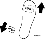
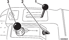
The traction pedal (Figure 15) has 3 functions: to make the machine move forward, to move it backward, and to stop the machine. Press the top of the pedal to move forward and the bottom of the pedal to move backward or to assist in stopping when moving forward. Also, allow the pedal to move to the NEUTRAL position to stop the machine. Do not rest the heel of your foot on reverse when operating forward (Figure 16).
Brake Pedal
Press the brake pedal (Figure 15) to stop the machine by actuating the front-wheel brakes.
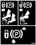
Parking-Brake Tab
To set the parking brake, press the brake pedal, then press the parking-brake tab (Figure 15) to engage the brakes. Disengage the tab by pressing the brake pedal. Engage the parking brake before you leave the machine.
Throttle Lever
The throttle lever (Figure 17) allows you to control the speed of the engine. Moving the throttle lever toward the FAST position increases the engine speed; moving the throttle lever toward the SLOW position decreases the engine speed, but does not shut off the engine.
Choke Lever
To start a cold engine, close the carburetor choke by pushing the choke lever forward (Figure 17) to the CLOSED position. After the engine starts, regulate the choke lever to keep the engine running smoothly. As soon as possible, open the choke by pulling the lever rearward to the OPEN position. A warm engine requires little or no choking.
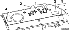
Leak-Detector Test Switch
Use the switch (Figure 17) to check the operation of the leak detector alarm and time delay.
Hour Meter
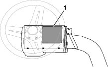
The hour meter (Figure 17) indicates the total hours the machine has operated. It starts to function whenever you rotate the key switch to the ON position.
Seat-Adjustment Lever
The seat adjustment lever is located at the left side of the seat (Figure 18). Moving the lever unlocks the seat and allows you to adjust the seat 10 cm (4 inches) forward and rearward.
Raise/Lower Mow Control
Move the raise/lower mow control (Figure 19) forward during cutting operation lowers the cutting units and starts the reels. Pull back the control to stop the reels and raise the cutting units. To stop the reels without raising the cutting units, pull back the control momentarily and release it; start the reels again by moving the control forward.
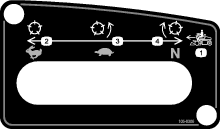
Functional Control Lever
The functional control lever (Figure 19) provides 2 traction selections plus a NEUTRAL position. You can shift from mow to transport or transport to mow (not to neutral) while the machine is in motion; no damage will result.
-
REAR position—neutral position; use when backlapping the reels
-
MIDDLE position—use when cutting grass
-
FRONT position—use when driving the machine between job sites
Ignition Switch
Insert the key into the switch (Figure 19) and turn it clockwise to the START position to start the engine. Release the key as soon as the engine starts; the key moves to the ON position. Turn the key counterclockwise to the STOP position to shut off the engine.
Steering-Wheel Locking Lever
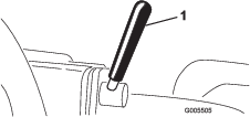
Rotate the lever (Figure 20) forward to loosen the adjustment, raise or lower steering wheel for your comfort, then, rotate the lever rearward to tighten the adjustment.
Steering-Arm Locking Knob
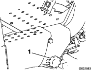
Loosen the knob (Figure 21) until the shoulder on the knob clears the notches in the steering arm. Raise or lower the steering arm to the desired height while aligning the shoulder of the knob with the notch in the steering arm. Tighten the knob to lock the adjustment.
Fuel-Shutoff Valve
Close the fuel-shutoff valve (Figure 22), under the fuel tank, when storing or transporting the machine on a truck or trailer.

Backlap Lever
Use the backlap lever (Figure 23) with the raise/lower mow control lever and the reel speed control for backlapping the reels.
Reel-Speed Control
Use the reel-speed control (Figure 23) to adjust the speed of the reels.
Note: Specifications and design are subject to change without notice.
| Width of cut | 150 cm (59 inches) |
| Wheel tread | 126 cm (49.5 inches) |
| Wheel base | 119 cm (46.9 inches) |
| Overall length | 229 cm (90 inches) |
| Overall width | 177 cm (69.75 inches) |
| Overall height | 189 cm (74.5 inches) |
| Net Weight | 493 kg (1,087 lb) |
Attachments/Accessories
A selection of Toro approved attachments and accessories is available for use with the machine to enhance and expand its capabilities. Contact your Authorized Service Dealer or authorized Toro distributor or go to www.Toro.com for a list of all approved attachments and accessories.
To ensure optimum performance and continued safety certification of the machine, use only genuine Toro replacement parts and accessories. Replacement parts and accessories made by other manufacturers could be dangerous, and such use could void the product warranty.
Operation
Note: Determine the left and right sides of the machine from the normal operating position.
Before Operation
Before Operation Safety
General Safety
-
Never allow children or untrained people to operate or service the machine. Local regulations may restrict the age of the operator. The owner is responsible for training all operators and mechanics.
-
Become familiar with the safe operation of the equipment, operator controls, and safety signs.
-
Always shut off the engine, remove the key (if equipped), wait for all moving parts to stop, and allow the machine to cool before adjusting, repairing, cleaning, or storing the machine. Know how to stop the machine and shut off the engine quickly.
-
Check that operator-presence controls, safety switches, and shields are attached and functioning properly. Do not operate the machine unless they are functioning properly.
-
Before mowing, always inspect the machine to ensure that the cutting units are in good working condition.
-
Inspect the area where you will use the machine and remove all objects that the machine could throw.
Fuel Safety
-
Use extreme care in handling fuel. It is flammable and its vapors are explosive.
-
Extinguish all cigarettes, cigars, pipes, and other sources of ignition.
-
Use only an approved fuel container.
-
Do not remove the fuel cap or fill the fuel tank while the engine is running or hot.
-
Do not add or drain fuel in an enclosed space.
-
Do not store the machine or fuel container where there is an open flame, spark, or pilot light, such as on a water heater or other appliance.
-
If you spill fuel, do not attempt to start the engine; avoid creating any source of ignition until the fuel vapors have dissipated.
Fuel Specification
Fuel tank capacity: 26.6 L (7 US gallons)
Recommended Fuel: Unleaded gasoline with an octane rating of 87 or higher ((R+M)/2 rating method)
Ethanol: Gasoline with up to 10% ethanol (gasohol) or 15% MTBE (methyl tertiary butyl ether) by volume is acceptable. Ethanol and MTBE are not the same. Gasoline with 15% ethanol (E15) by volume is not approved for use.
-
Never use gasoline that contains more than 10% ethanol by volume, such as E15 (contains 15% ethanol), E20 (contains 20% ethanol), or E85 (contains up to 85% ethanol).
-
Do not use fuel that contains methanol.
-
Do not store fuel either in the fuel tank or fuel containers over the winter, unless you use a fuel stabilizer.
-
Do not add oil to gasoline.
-
For best results, use only clean, fresh (less than 30 days old) fuel.
-
Using unapproved gasoline may cause performance problems and/or engine damage, which may not be covered under the warranty.
Important: Do not use fuel additives other than a fuel stabilizer/conditioner. Do not use fuel stabilizers with an alcohol base such as ethanol, methanol, or isopropanol.
Filling the Fuel Tank
-
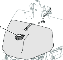
Clean around the fuel-tank cap and remove it (Figure 24).
-
Add the specified fuel to the fuel tank until the level is 25 mm (1 inch) below the bottom of the filler neck.
This space in the tank allows the fuel to expand. Do not fill the fuel tank completely full.
-
Install the cap.
Note: You will hear a click sound when the cap is secure.
-
Wipe up any spilled fuel.
Performing Daily Maintenance
Before starting the machine each day, perform the following procedures:
-
Check the engine-oil level—refer to Checking the Engine Oil.
-
Check the hydraulic-fluid level—refer to Checking the Hydraulic-Fluid Level.
-
Check the reel-to-bedknife contact—refer to Checking the Reel-to-Bedknife Contact.
-
Check the tire pressure—refer to Checking the Tire Pressure.
During Operation
During Operation Safety
General Safety
-
The owner/operator can prevent and is responsible for accidents that may cause personal injury or property damage.
-
Wear appropriate clothing, including eye protection; long pants; substantial, slip-resistant footwear; and hearing protection. Tie back long hair and do not wear loose clothing or loose jewelry.
-
Do not operate the machine while ill, tired, or under the influence of alcohol or drugs.
-
Use your full attention while operating the machine. Do not engage in any activity that causes distractions; otherwise, injury or property damage may occur.
-
Before you start the engine, ensure that all drives are in neutral, the parking brake is engaged, and you are in the operating position.
-
Do not carry passengers on the machine and keep bystanders and pets away from the machine during operation.
-
Operate the machine only in good visibility to avoid holes or hidden hazards.
-
Avoid mowing on wet grass. Reduced traction could cause the machine to slide.
-
Keep your hands and feet away from the cutting units. Keep clear of the discharge opening at all times.
-
Look behind and down before backing up to be sure of a clear path.
-
Use care when approaching blind corners, shrubs, trees, or other objects that may obscure your vision.
-
Stop the cutting units whenever you are not mowing.
-
Slow down and use caution when making turns and crossing roads and sidewalks with the machine. Always yield the right-of-way.
-
Disengage the drive to the cutting unit and shut off the engine before adjusting the height of cut (unless you can adjust it from the operating position).
-
Never run an engine in an area where exhaust gasses are enclosed.
-
Never leave a running machine unattended.
-
Before leaving the operating position (including to empty the catchers or to unclog the cutting units), do the following:
-
Park the machine on level ground.
-
Disengage the power take-off and lower the attachments.
-
Engage the parking brake.
-
Shut off the engine and remove the key.
-
Wait for all moving parts to stop.
-
Rollover Protection System (ROPS) Safety
-
Do not remove the ROPS from the machine.
-
Ensure that the seat belt is attached and that you can release it quickly in an emergency.
-
Always wear your seat belt.
-
Check carefully for overhead obstructions and do not contact them.
-
Keep the ROPS in safe operating condition by thoroughly inspecting it periodically for damage and keeping all the mounting fasteners tight.
-
Replace a damaged ROPS. Do not repair or alter it.
Slope Safety
-
Slopes are a major factor related to loss of control and rollover accidents, which can result in severe injury or death. You are responsible for safe slope operation. Operating the machine on any slope requires extra caution.
-
Evaluate the site conditions to determine if the slope is safe for machine operation, including surveying the site. Always use common sense and good judgment when performing this survey.
-
Review the slope instructions, listed below, for operating the machine on slopes. Before you operate the machine, review the site conditions to determine whether you can operate the machine in the conditions on that day and at that site. Changes in the terrain can result in a change in slope operation for the machine.
-
Avoid starting, stopping, or turning the machine on slopes. Avoid making sudden changes in speed or direction. Make turns slowly and gradually.
-
Do not operate a machine under any conditions where traction, steering, or stability is in question.
-
Remove or mark obstructions such as ditches, holes, ruts, bumps, rocks, or other hidden hazards. Tall grass can hide obstructions. Uneven terrain could overturn the machine.
-
Be aware that operating the machine on wet grass, across slopes, or downhill may cause the machine to lose traction. Loss of traction to the drive wheels may result in sliding and a loss of braking and steering.
-
Use extreme caution when operating the machine near drop-offs, ditches, embankments, water hazards, or other hazards. The machine could suddenly roll over if a wheel goes over the edge or the edge caves in. Establish a safety area between the machine and any hazard.
-
Identify hazards at the base of the slope. If there are hazards, mow the slope with a pedestrian-controlled machine.
-
If possible, keep the cutting units lowered to the ground while operating on slopes. Raising the cutting units while operating on slopes can cause the machine to become unstable.
-
Use extreme caution with grass-collection systems or other attachments. These can change the stability of the machine and cause a loss of control.
-
Breaking in the Machine
Refer to the engine manual supplied with the machine for oil change and maintenance procedures recommended during the break-in period.
Only 8 hours of operation is required for the break-in period.
Since the first hours of operation are critical to future dependability of the machine, monitor its functions and performance closely so that minor difficulties, which could lead to major problems, are noted and can be corrected. Inspect the machine frequently during break-in for signs of oil leakage, loose fasteners, or any other malfunction.
Starting the Engine
Note: Inspect the area beneath the mowers to be certain they are clear of debris.
-
Sit on the seat, ensure that the parking brake is engaged, disengage the raise/lower mow control, and move the functional control lever to the NEUTRAL position.
-
Ensure that your foot is not on the traction pedal and make sure the pedal is in the NEUTRAL position.
-
Move the choke lever to the ON position (only when starting a cold engine) and the throttle lever to the HALF THROTTLE position.
-
Start the engine and regulate the choke to keep it running smoothly.
-
As soon as possible, open the choke by pulling it rearward to the OFF position.
Note: A warm engine requires little or no choking.
-
Check the machine out with the following procedures after the engine has started:
-
Move the throttle lever to the FAST position.
-
Move the traction-control lever to the MOW position and momentarily engage the reels by moving the raise/lower mow-control lever forward.
The cutting units should drop and all the reels should rotate.
-
Move the raise/lower mow control lever rearward until the cutting units raise to the full transport position.
The cutting units stop rotating as soon as they start to lift. If you release the lever before the cutting units are fully raised, the upward motion stops, but the cutting units still stop rotating.
-
Lock the parking brake and shut off the engine.
-
Check the lip of each basket to ensure it is not in contact with the reel during operation.
If you see signs of contact, adjust the pull arms; refer to Installing the Cutting Units.
-
Check for oil leaks and tighten the hydraulic fittings if any are found.
Note: When the machine is new and the bearings and reels are tight, it is necessary to use the FAST throttle lever position for this check. A fast throttle setting may not be required after the break-in period.
Note: If oil leaks continue to appear, contact your authorized Toro distributor for assistance and, if necessary, replacement parts.
Important: A trace of oil on the motor or wheel seals is normal. Seals require a small amount of lubrication to perform properly.
-
Checking the Machine After Starting the Engine
-
Move the throttle lever to the FAST position.
-
Move the raise/lower mow control lever forward momentarily.
The cutting units should lower and all the reels should rotate.
Note: The function lever should be in the middle (mow) position for the reels to run when lowering the cutting units
-
Move the raise/lower mow control lever rearward.
The cutting reels should stop rotating and the cutting units should raise to the full transport position.
-
Engage the brake to keep the machine from moving, and operate the traction pedal through the forward and reverse positions.
-
Continue the above procedure for 1 to 2 minutes. Move the functional-control lever to the NEUTRAL position, lock the parking brake, and shut off the engine.
-
Check for fluid leaks and tighten the hydraulic fittings if any leaks are found.
Note: When the machine is new and the bearings and reels are tight, it is necessary to use the FAST throttle lever position for this check. A fast throttle setting may not be required after the break-in period.
Note: If fluid leaks continue to appear, contact your authorized Toro distributor for assistance and, if necessary, replacement parts.
Important: A trace of fluid on the motor or wheel seals is normal. Seals require a small amount of lubrication to perform properly.
Shutting Off the Engine
-
Move the throttle lever to the SLOW position, pull back the raise/lower mow control, and move the functional-control lever to the NEUTRAL position.
-
Rotate the ignition key to the OFF position to shut off the engine. Remove the key from the switch to prevent accidental starting.
-
Close the fuel shut-off valve before storing the machine.
Checking the Safety-Interlock System
| Maintenance Service Interval | Maintenance Procedure |
|---|---|
| Before each use or daily |
|
Caution
If the safety interlock switches are disconnected or damaged the machine could operate unexpectedly, causing personal injury.
-
Do not tamper with the interlock switches.
-
Check the operation of the interlock switches daily and replace any damaged switches before operating the machine.
The purpose of the safety-interlock system is to prevent operation of the machine where there is possible injury to you or damage to the machine.
The safety-interlock system prevents the engine from starting unless:
-
The traction pedal is in the NEUTRAL position.
-
The functional-control lever is in the NEUTRAL position.
The safety-interlock system prevents the machine from moving unless:
-
The parking brake is disengaged.
-
You are seated in the operator's seat.
-
The functional-control lever is in the MOW position or the TRANSPORT position.
The safety-interlock system prevents the reels from operating unless the functional-control lever is in the MOW position.
Checking the Traction Pedal
| Maintenance Service Interval | Maintenance Procedure |
|---|---|
| Before each use or daily |
|
Perform the following system checks daily to ensure that the interlock system is operating correctly:
-
Sit on the seat, move the traction pedal to the NEUTRAL position, move the functional-control lever to the NEUTRAL position, and engage the parking brake.
-
Try to move the traction pedal forward or backward.
The pedal should not move, which indicates that the interlock system is operating correctly. Correct the problem if it is not operating properly.
Checking the Function Control
-
Sit on the seat, move the traction pedal to the NEUTRAL position, move the functional-control lever to the NEUTRAL position, and engage the parking brake.
-
Move the functional-control lever to the MOW position or the TRANSPORT position and try to start the engine.
The engine should not turnover or start, which indicates that the interlock system is operating correctly. Correct the problem if it is not operating properly.
-
Sit on the seat, move the traction pedal to the NEUTRAL position, move the functional-control lever to the NEUTRAL position, and engage the parking brake.
-
Start the engine and move the functional-control lever to the MOW position or the TRANSPORT position.
The engine should shut off, which indicates that the interlock system is operating correctly.
Correct the problem if it is not operating properly.
Checking the Operator’s Presence Switch
-
Sit on the seat, move the traction pedal to the NEUTRAL position, move the functional control lever to the NEUTRAL position, and engage the parking brake.
-
Start the engine.
-
Release the parking brake, move the functional control lever to the MOW position, and rise from the seat.
The engine should shut off, which indicates that the interlock system is operating correctly. Correct the problem if it is not operating properly.
Checking the Raise/Lower Mow Control
-
Sit on the seat, move the traction pedal to the NEUTRAL position, move the functional control lever to the NEUTRAL position, and engage the parking brake.
-
Start the engine.
-
Move the raise/lower mow control forward to lower the cutting units. The cutting units should lower but not start rotating.
If they start rotating, the interlock system is not operating correctly; correct the problem before operating the machine.
Driving the Machine without Mowing
-
Ensure that the cutting units are fully raised.
-
Move the functional-control lever to the TRANSPORT position.
-
Use the brakes to slow the machine while going down steep hills to avoid loss of control.
-
Always approach rough areas at a reduced speed and cross severe undulations carefully.
-
Familiarize yourself with the width of the machine. Do not attempt to pass between objects that are close together to prevent costly damage and downtime.
Mowing the Green
Important: If the leak detector alarm (if equipped on your model) sounds or you notice an oil leak while cutting on a green, immediately raise the cutting units, drive directly off the green, and stop the machine in an area away from the green. Determine the cause of the leak and correct the problem.
Before mowing greens, find a clear area and practice performing basic machine functions (e.g., starting and stopping the machine, raising and lowering the cutting units, and turning).
Inspect the green for debris, remove the flag from the cup, and determine the best direction to mow. Base the direction to mow on the previous mowing direction. Always mow in an alternate pattern from the previous mowing so that the grass blades are less apt to lay down and therefore be difficult to trap between the reel blades and the bedknife.
Cutting the Green
-
Approach the green with the functional-control lever in the MOW position and the throttle at full speed.
-
Start on 1 edge of the green so that you can use the ribbon procedure of cutting.
Note: This holds compaction to a minimum and leaves a neat, attractive pattern on the greens.
-
Push forward the raise/lower mow lever as the front edges of the grass baskets cross the outer edge of the green.
Note: This procedure drops the cutting units to the turf and starts the reels.
Important: The center cutting unit drops and raises slightly after the front cutting units do; therefore, you should practice gaining the required timing necessary to minimize the cleanup mowing operation.
Note: The delay in raising and lowering the center cutting unit depends on hydraulic fluid temperature. Cold hydraulic fluid results in a longer delay. As the fluid temperature increases, the delay time becomes shorter.
-
Overlap a minimal amount with the previous cut on return passes.
Note: To assist in maintaining a straight line across the green and keeping the machine an equal distance from the edge of the previous cut, imagine a sight line approximately 1.8 to 3 m (6 to 10 ft) ahead of the machine to the edge of the uncut portion of the green (Figure 26). Include the outer edge of the steering wheel as part of the sight line; i.e., keep the steering wheel edge aligned with a point that is always kept the same distance away from the front of the machine.
-
As the front edges of the baskets cross the edge of the green, pull back the raise/lower mow lever rearward and hold it until all the cutting units have risen. This stops the reels and lifts the cutting units.
Important: Time this step correctly so that you do not cut into the fringe area, yet cut as much of the green as possible to minimize the amount of grass left to mow around the outer periphery.
-
To cut down on operating time and to ease the lineup for the next pass, momentarily turn the machine in the opposite direction, then turn it in the direction of the uncut portion. This movement is a tear-shaped turn (Figure 25), which quickly lines the machine up for your next pass.
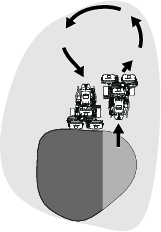
Note: Try to make as short of a turn as possible, except during warmer weather—a wider arc minimizes the turf bruising.
Note: The steering wheel does not return to its original position after you complete a turn.
Important: Never stop the machine on a green while the cutting units are engaged, as damage to the turf may result. Stopping the machine on a wet green may leave marks or indentations from the wheels.
Cutting the Periphery and Finishing the Job
-
Finish cutting the green by mowing the outer periphery. Change the direction of cutting from the previous mowing.
Note: Use the throttle lever to adjust the machine speed when you cut the periphery. This will match the clip to the green and may reduce triplex ring.
Note: Always keep weather and turf conditions in mind and be sure to change the direction of mowing from the previous cutting.
-
When finished mowing the outer periphery, tap the raise/lower mow lever rearward to stop the reels, then drive off the green. When all the cutting units are off the green, raise the cutting units.
Note: This step minimizes grass clumps left on the green.
-
Replace the flag.
-
Empty the grass baskets of all clippings before you transport the machine to the next green.
Note: Heavy wet clippings place an undue strain on the baskets and add unnecessary weight to the machine, which increases the load on the machine systems (e.g., engine, hydraulic system, and brakes).
After Operation
After Operation Safety
General Safety
-
Always shut off the engine, remove the key (if equipped), wait for all moving parts to stop, and allow the machine to cool before adjusting, repairing, cleaning, or storing the machine.
-
Clean grass and debris from the cutting units, drives, mufflers, cooling screens, and engine to help prevent fires. Clean up oil or fuel spills.
-
Shut off the fuel while storing or transporting the machine.
-
Disengage the drive to the attachment whenever you are transporting or not using the machine.
-
Allow the engine to cool before storing the machine in any enclosure.
-
Maintain and clean the seat belt(s) as necessary.
-
Do not store the machine or fuel container where there is an open flame, spark, or pilot light, such as on a water heater or on other appliances.
Towing Safety
-
Tow only with a machine that has a hitch designed for towing. Do not attach towed equipment except at the hitch point.
-
Follow the manufacturer’s recommendation for weight limits for towed equipment and towing on slopes. On slopes, the weight of the towed equipment may cause loss of traction and loss of control.
-
Never allow children or others in or on towed equipment.
-
Travel slowly and allow extra distance to stop when towing.
Towing the Machine
In case of an emergency, you can tow the machine for up to 0.4 km (1/4 mile).
Important: Do not tow the machine faster than 3 to 5 km/h (2 to 3 mph) to avoid damaging the drive system. If you must move the machine more than 0.4 km (1/4 mile), transport it on a truck or trailer.
Inspecting and Cleaning after Mowing
| Maintenance Service Interval | Maintenance Procedure |
|---|---|
| Before each use or daily |
|
After mowing, thoroughly wash the machine with a garden hose without a nozzle so that excessive water pressure does not contaminate and damage the seals and bearings. Do not wash a warm engine or the electrical connections with water.
After cleaning the machine, do the following:
-
Inspect the machine for possible hydraulic fluid leaks, damage or wear to hydraulic and mechanical components.
-
Inspect the cutting units for sharpness.
-
Lubricate the brake-shaft assembly with SAE 30 oil or spray lubricant to deter corrosion and help keep the machine performing satisfactorily during the next mowing operation.
Hauling the Machine
-
Use care when loading or unloading the machine into a trailer or a truck.
-
Use a full-width ramp for loading the machine into a trailer or a truck.
-
Tie the machine down securely using straps, chains, cable, or ropes. Both front and rear straps should be directed down and outward from the machine (Figure 28).
Maintenance
Caution
Failure to properly maintain the machine could result in premature failure of machine systems causing possible harm to you or bystanders.
Keep the machine well maintained and in good working order as indicated in these instructions.
Note: Determine the left and right sides of the machine from the normal operating position.
Note: Download a free copy of the electrical or hydraulic schematic by visiting www.Toro.com and searching for your machine from the Manuals link on the home page.
Important: Refer to your engine owner's manual for additional maintenance procedures.
Warning
If you leave the key in the ignition switch, someone could accidently start the engine and seriously injure you or other bystanders.
Remove the key from the ignition and disconnect the wires from the spark plugs before you do any maintenance. Set the wires aside so that they do not accidentally contact the spark plugs.
Maintenance Safety
-
Before adjusting, cleaning, repairing, or leaving the machine, do the following:
-
Park the machine on a level surface.
-
Move the throttle switch to the low-idle position.
-
Disengage the cutting units.
-
Lower the cutting units.
-
Ensure that the traction is in neutral.
-
Engage the parking brake.
-
Shut off the engine and remove the key.
-
Wait for all moving parts to stop.
-
Allow machine components to cool before performing maintenance.
-
-
If the cutting units are in the transport position, use the positive mechanical lock (if available) before you leave the machine unattended.
-
If possible, do not perform maintenance while the engine is running. Keep away from moving parts.
-
Use jack stands to support the machine or components when required.
-
Carefully release pressure from components with stored energy.
-
To ensure safe, optimal performance of the machine, use only genuine Toro replacement parts. Replacement parts made by other manufacturers could be dangerous, and such use could void the product warranty.
Recommended Maintenance Schedule(s)
| Maintenance Service Interval | Maintenance Procedure |
|---|---|
| After the first hour |
|
| After the first 10 hours |
|
| After the first 50 hours |
|
| Before each use or daily |
|
| Every 50 hours |
|
| Every 100 hours |
|
| Every 200 hours |
|
| Every 800 hours |
|
| Every 1,000 hours |
|
| Every 2,000 hours |
|
| Yearly |
|
| Every 2 years |
|
Pre-Maintenance Procedures
Removing the Seat Assembly
Note: If you remove the seat assembly frequently, you can replace the roll pin with an R-key pin (Part No. 3290-467).
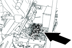
Remove the seat assembly to access the valve block area of the machine.
-
Unlatch and raise the seat, securing it with the prop rod.
-
Disconnect the 2 wire-harness connectors under the seat.
-
Lower the seat and remove the roll pin securing the seat-pivot rod to the frame (Figure 29).
-
Slide the seat-pivot rod to the left.
-
Move the seat forward and lift it out of the machine.
-
Reverse the procedure to install the seat.
Raising the Machine
Caution
If the machine is not properly supported, it could fall, crushing you or others.
Before servicing, support the machine with jack stands or blocks of wood.
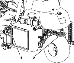
Before raising the machine, lower the cutting units. The jacking points are as follows:
-
Right side—under the jack pad and adjacent to the ROPS-support bracket (Figure 30)
-
Left side—under the step
-
Rear—at the caster fork
Lubrication
Greasing the Machine
| Maintenance Service Interval | Maintenance Procedure |
|---|---|
| Every 50 hours |
|
Lubricate the grease fittings regularly with No. 2 lithium grease.
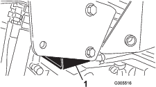
Locate the grease fitting as follows:
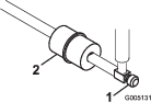
-
Rear-roller-hub assembly or, if equipped with a 3-wheel-drive kit, rear-wheel-roller clutches and external ball bearing (1) (Figure 31)
-
Steering-fork shaft (1) (Figure 32)
-
Steering-cylinder-rod end (Figure 32)
-
Lift-arm pivot (3) and pivot hinge (3) (Figure 33)
-
Pull-frame shaft and roller (12) (Figure 34)
-
Steering-cylinder end (Figure 35)
-
Lift cylinders (3) (Figure 36)
-
Traction pedal (Figure 37)
-
Speed-selector linkage (Figure 38 and Figure 39)
-
Wipe the grease fitting clean so foreign matter cannot be forced into the bearing or bushing.
-
Pump grease into the bearing or bushing until the grease is visible. Wipe up excess grease.
-
Apply grease to the reel motor spline shaft and onto the lift arm when you remove the cutting unit for service.
-
Apply a few drops of SAE 30 engine oil or spray lubricant (WD 40) to all pivot points daily after cleaning.
Engine Maintenance
Engine Safety
-
Shut off the engine before checking the oil or adding oil to the crankcase.
-
Do not change the governor speed or overspeed the engine.
Servicing the Air Cleaner
| Maintenance Service Interval | Maintenance Procedure |
|---|---|
| Every 50 hours |
|
| Every 100 hours |
|
-
Clean the air-cleaner cover (Figure 40).
-
Release the locking clips and remove the air-cleaner cover.
-
Remove the wing nut securing the elements to the air-cleaner body (Figure 41).
-
If the foam element is dirty, remove it from the paper element (Figure 41). Clean it thoroughly, as follows:
-
Wash the foam element in a solution of liquid soap and warm water. Squeeze it to remove dirt.
-
Dry it by wrapping it in a clean rag. Squeeze the rag and foam element dry.
Important: When drying the foam element, do not twist it; the foam may tear.
-
-
Check the condition of the paper element. Clean it by gently tapping it on a flat surface or replace it if needed.
-
Install the foam element, paper element, wing nut, and air-cleaner cover.
Important: Do not operate the engine without the air-cleaner element because extreme engine wear and damage will likely result.
Servicing the Engine Oil
The engine is shipped with oil in the crankcase; however, you must check the oil level before and after starting the engine the first time.
Engine Oil Specification
API Oil Service Classification: SJ or higher
Oil Viscosity: SAE 30
Note: Uses any high-quality detergent oil.
Checking the Engine Oil
| Maintenance Service Interval | Maintenance Procedure |
|---|---|
| Before each use or daily |
|
-
Park the machine on a level surface, shut off the engine and remove the key.
-
Unscrew the dipstick, remove it, and wipe it with a clean rag.
-
Insert the dipstick into the dipstick tube and thread it into the tube (Figure 42).
-
Unscrew the dipstick, pull it out of the tube, and check the oil level.
-
If the oil level is low, remove the filler cap from the valve cover and add oil into the engine through the filler neck until the oil level is up to the FULL mark on the dipstick.
Add the oil slowly and check the level often during this process.
Important: Do not overfill the engine with oil.
-
Install the filler cap and dipstick.
Changing the Engine Oil and Filter
| Maintenance Service Interval | Maintenance Procedure |
|---|---|
| Every 100 hours |
|
Engine oil quantity: 1.4 L (1.5 US qt) with filter
-
Remove the drain plug (Figure 43) and let the oil flow into a drain pan.
-
Clean the threads of the drain plug, apply PTFE sealant, and install the drain plug (Figure 43).
-
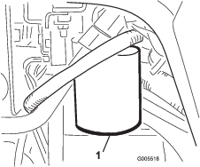
Remove the oil filter (Figure 43).
-
Apply a light coat of clean oil to the new filter gasket.
-
Thread the oil filter onto the engine by hand until the gasket contacts the filter adapter, then tighten the filter 3/4 to 1 turn further.
Important: Do not overtighten the oil filter.
-
Add oil to the crankcase; refer to Engine Oil Specification and Checking the Engine Oil.
-
Dispose of the oil filter and used oil properly.
Replacing the Spark Plugs
| Maintenance Service Interval | Maintenance Procedure |
|---|---|
| Every 1,000 hours |
|
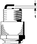
Spark plug specification: Champion RC 14YC
Air gap specification: 0.76 mm (0.030 inch)
-
Clean the area around the spark plugs so that foreign matter cannot fall into the cylinder.
-
Pull the wires off the spark plugs and remove the plugs.
-
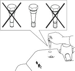
Check the condition of the side electrode, center electrode, and center electrode insulator to ensure that there is no damage.
Important: Replace a cracked, fouled, dirty, or otherwise malfunctioning spark plug. Do not sand blast, scrape, or clean electrodes by using a wire brush because grit may eventually release from the plug, fall into the cylinder, and damage the engine.
-
Set the air gap between the center and side of the electrodes at 0.76 mm (0.030 inches) as shown in Figure 44.
-
Install the spark plug and gasket seal, and torque the plug to 23 N∙m (200 in-lb).
Fuel System Maintenance
Replacing the Fuel Filter
| Maintenance Service Interval | Maintenance Procedure |
|---|---|
| Every 800 hours |
|
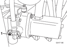
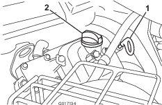
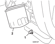
The in-line fuel filter is in the fuel line between the fuel tank and carburetor (Figure 45).
Danger
In certain conditions, fuel is extremely flammable and highly explosive. A fire or explosion from fuel can burn you and others and can damage property.
-
Drain fuel from the fuel tank when the engine is cold. Do this outdoors in an open area. Wipe up any fuel that spills.
-
Never smoke when draining fuel, and stay away from an open flame or where a spark may ignite the fumes.
-
Close the fuel-shutoff valve (Figure 45).
-
Place a drain pan under the filter, loosen the hose clamp on the carburetor side of filter, and remove the fuel line from the filter (Figure 45).
-
Loosen the other hose clamp and remove the filter (Figure 45).
-
Install the new filter with the arrow on the filter body pointing away from the fuel tank.
Inspecting the Fuel Lines and Connections
| Maintenance Service Interval | Maintenance Procedure |
|---|---|
| Every 2 years |
|
Inspect the fuel lines for deterioration, damage, or loose connections.
Electrical System Maintenance
Electrical System Safety
-
Disconnect the battery before repairing the machine. Disconnect the negative terminal first and the positive last. Connect the positive terminal first and the negative last.
-
Charge the battery in an open, well-ventilated area, away from sparks and flames. Unplug the charger before connecting or disconnecting the battery. Wear protective clothing and use insulated tools.
Servicing the Battery
| Maintenance Service Interval | Maintenance Procedure |
|---|---|
| After the first 50 hours |
|
| Every 50 hours |
|
Properly maintain the battery electrolyte and keep the top of the battery clean. Store the machine in a cool place to prevent the battery from running down.
The battery cables must be tight on the terminals to provide good electrical contact.
Danger
Battery electrolyte contains sulfuric acid which can be fatal if consumed and causes severe burns.
-
Do not drink electrolyte and avoid contact with skin, eyes, or clothing. Wear safety glasses to shield your eyes and rubber gloves to protect your hands.
-
Fill the battery where clean water is always available for flushing the skin.
-
Check the electrolyte level in the cells of the battery.
-
If needed, add distilled or demineralized water into the cell of the battery.
Note: Only raise the electrolyte level to the bottom of the split ring inside each cell.
-
Clean the top of the battery by washing it periodically with a brush dipped in ammonia or bicarbonate of soda solution.
-
Flush the top surface of the battery with water after cleaning it.
Important: Do not remove the fill caps while cleaning the battery.
Warning
Incorrect battery cable routing could damage the machine and cables causing sparks. Sparks can cause the battery gasses to explode, resulting in personal injury.
-
Always disconnect the negative (black) battery cable before disconnecting the positive (red) cable.
-
Always connect the positive (red) battery cable before connecting the negative (black) cable.
If corrosion occurs at the terminals, disconnect the cables, negative (-) cable first, and scrape the clamps and terminals separately. Connect the cables, positive (+) cable first, and coat the terminals with petroleum jelly.
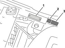
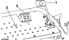
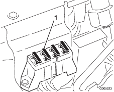
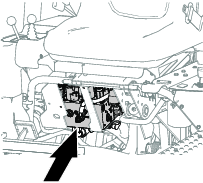
Locating the Fuses
The fuses in the electrical system of the machine are located under the seat (Figure 46).
Drive System Maintenance
Checking the Tire Pressure
| Maintenance Service Interval | Maintenance Procedure |
|---|---|
| Before each use or daily |
|
Vary the tire pressure for the front wheels, depending upon your turf conditions, from a minimum of 55 kPa (8 psi) to a maximum of 83 kPa (12 psi).
Vary the tire pressure for the rear wheel from a minimum of 55 kPa (8 psi) to a maximum of 103 kPa (15 psi).
Checking the Torque of the Wheel Nuts
| Maintenance Service Interval | Maintenance Procedure |
|---|---|
| After the first hour |
|
| After the first 10 hours |
|
| Every 200 hours |
|
Warning
Failure to maintain proper torque of the wheel nuts could result in personal injury.
Torque the wheel nuts to the specified torque at the specified intervals.
Wheel nut torque specification: 95 to 122 N∙m (70 to 90 ft-lb)
Note: To ensure even distribution, torque the wheel nuts in a X pattern.
Adjusting the Transmission for Neutral
If the machine creeps when the traction control pedal is in the NEUTRAL position, adjust the neutral-return mechanism.
-
Block up under the frame so that one of the front wheels is off of the floor.
Note: If the machine is equipped with a 3-Wheel Drive Kit, raise and block the rear wheel.
-
Start the engine, move the throttle to the SLOW position, and ensure that the front wheel that is off of the floor is not rotating.
-
If the wheel is rotating, shut off the engine and proceed as follows:
-
Loosen both jam nuts securing the traction-control cable to the bulkhead on the hydrostat (Figure 47). Ensure that the jam nuts are loosened equally and sufficiently to allow adjustment.
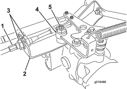
Note: Loosen the nut securing the eccentric to the top of the hydrostat (Figure 47).
-
Move the functional-control lever to the NEUTRAL position and the throttle lever to the SLOW position.
-
Start the engine.
-
Rotate the eccentric until creep does not occur in either direction.
-
When the wheel stops rotating, tighten the nut locking the eccentric and the adjustment (Figure 47).
-
Verify the adjustment with the throttle lever in the SLOW and FAST position.
-
From each side of the bulkhead, tighten the locknuts evenly, securing the traction cable to the bulkhead (Figure 47). Do not twist the cable.
Note: If cable tension exists when the functional-control lever is in the NEUTRAL position, the machine may creep when you move the lever to the MOW or TRANSPORT position.
-
Adjusting the Transport Speed
Obtaining the Maximum Transport Speed
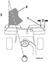
The traction pedal comes adjusted for maximum-transport speed, but you may need to adjust it if the pedal reaches full stroke before it contacts the pedal stop, or if you want to a decrease the transport speed.
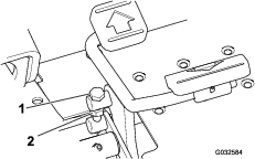
To obtain the maximum-transport speed, put the functional control lever in the TRANSPORT position and press down on the traction pedal. If the pedal contacts the stop (Figure 48) before you feel tension on the cable, perform the following adjustment procedure:
-
Put the functional-control lever in the TRANSPORT position and loosen the locknut securing the pedal stop to the floor plate (Figure 48).
-
Tighten the pedal stop until it does not contact the traction pedal.
-
Continue applying a light load on the transport pedal and adjust the pedal stop so it contacts the pedal rod and tighten the nuts.
Important: Ensure that the tension on the cable is not excessive or you will reduce the cable life.
Reducing the Transport Speed
-
Press down on the traction pedal and loosen the locknut securing the pedal stop to the floor plate.
-
Loosen the pedal stop until you obtain the desired transport speed.
-
Tighten the locknut securing the pedal stop.
Adjusting the Mowing Speed
Factory setting: 6.1 km/h (3.8 mph)
-
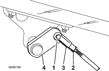
Loosen the jam nut on the trunnion bolt on the side of the traction pedal (Figure 49).
-
Rotate the trunnion bolt counterclockwise to increase the mowing speed and clockwise to decrease it.
-
Tighten the jam nut without turning the trunnion bolt and check the ground speed. Repeat this procedure, if required.
Brake Maintenance
Burnishing the Brakes
| Maintenance Service Interval | Maintenance Procedure |
|---|---|
| Yearly |
|
Firmly apply the brakes and drive the machine at mowing speed until the brakes are hot, as indicated by their smell. You may need to adjust the brakes after the break-in period; refer to Adjusting the Brakes.
Adjusting the Brakes
A brake adjustment rod is located at each side of the machine so that you can adjust the brakes equally.
-
While moving forward in transport speed, press the brake pedal; both wheels should apply equally.
Caution
Testing the brakes in a confined area where others are present could cause injury.
Always check the brakes in a wide, open-spaced, flat area free from people and obstructions before and after the adjustment.
-
If the brakes do not apply equally, adjust the brakes as follows:
-
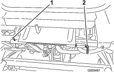
Disconnect the brake rods by removing the cotter pin and clevis pin (Figure 50).
-
Loosen the jam nut and adjust the clevis accordingly (Figure 50).
-
Assemble the clevis to the brake shaft (Figure 50).
-
When you press the brake pedal, the pedal should move 13 to 26 mm (1/2 to 1 inch) travel before the brake shoes contacts the brake drums. Adjust the clevis on the brake shaft, if necessary, to achieve this setting.
-
While moving forward in transport speed, press the brake pedal; both brakes should apply equally. Adjust them, if necessary.
-
Important: Burnish the brakes annually; refer to the Burnishing the Brakes section.
Controls System Maintenance
Adjusting the Cutting Unit Lift/Drop
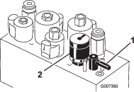
The cutting unit lift/drop circuit comes with a flow-control valve (Figure 51). This valve is preset at the factory at approximately 3 turns open, but you may need to adjust it to compensate for differences in hydraulic fluid temperatures, mowing speeds, etc.
Note: Allow the hydraulic fluid to reach full operating temperature before adjusting the flow-control valve.
-
Locate the flow-control valve below the seat (Figure 51).
-
Loosen the jam nut at the adjusting knob on the flow control valve.
-
Adjust the flow control valve as follows:
-
Rotate the knob counterclockwise if the center cutting unit is dropping too late or
-
Rotate the knob clockwise if the center cutting unit is dropping too early.
Note: You should not need to rotate it more than 1/32 to 1/16 of a turn.
-
-
Test the adjustment and repeat step 3 as needed; when finished, tighten the jam nut.
Adjusting the Lift Cylinders
To regulate the height of the front cutting units when in the raised (transport) position, you can adjust the front-lift cylinders.
-
Lower the cutting units to the ground.
-
Remove the bolts that secure the cover plate of the lift cylinder that you are adjusting from the support brackets of the chassis (Figure 52).
-
Loosen the jam nut securing the clevis fitting to the cylinder of the cutting-unit that needs to be adjusted (Figure 53).
-
Remove the retaining pin and clevis pin (Figure 53)
-
Rotate the clevis until you attain the desired height (Figure 54).
-
Assemble the clevis fitting to the lift arm with the clevis pin and retaining pin, and tighten the jam nut (Figure 53 and Figure 54).
-
Install the cover plate and bolts that you removed in step 2.
Hydraulic System Maintenance
Hydraulic System Safety
-
Seek immediate medical attention if fluid is injected into skin. Injected fluid must be surgically removed within a few hours by a doctor.
-
Ensure that all hydraulic-fluid hoses and lines are in good condition and all hydraulic connections and fittings are tight before applying pressure to the hydraulic system.
-
Keep your body and hands away from pinhole leaks or nozzles that eject high-pressure hydraulic fluid.
-
Use cardboard or paper to find hydraulic leaks.
-
Safely relieve all pressure in the hydraulic system before performing any work on the hydraulic system.
Servicing the Hydraulic Fluid
Important: Regardless of the hydraulic fluid type used, any traction unit used for off-green applications, verticutting or used during ambient temperatures above 29°C (85°F) should have the Oil Cooler Kit (Part No. 105-8339) installed.
Hydraulic Fluid Specifications
The reservoir is filled at the factory with high-quality hydraulic fluid. Check the level of the hydraulic fluid before you first start the engine and daily thereafter; refer to Checking the Hydraulic-Fluid Level.
Recommended hydraulic fluid: Toro PX Extended Life Hydraulic Fluid; available in 19 L (5 US gallon) pails or 208 L (55 US gallon) drums.
Note: A machine using the recommended replacement fluid requires less frequent fluid and filter changes.
Alternative hydraulic fluids: If Toro PX Extended Life Hydraulic Fluid is not available, you may use another conventional, petroleum-based hydraulic fluid having specifications that fall within the listed range for all the following material properties and that it meets industry standards. Do not use synthetic fluid. Consult with your lubricant distributor to identify a satisfactory product.
Note: Toro does not assume responsibility for damage caused by improper substitutions, so use products only from reputable manufacturers who will stand behind their recommendation.
| Material Properties: | ||
| Viscosity, ASTM D445 | cSt @ 40°C (104°F) 44 to 48 | |
| Viscosity Index ASTM D2270 | 140 or higher | |
| Pour Point, ASTM D97 | -37°C to -45°C (-34°F to -49°F) | |
| Industry Specifications: | Eaton Vickers 694 (I-286-S, M-2950-S/35VQ25 or M-2952-S) | |
Note: Many hydraulic fluids are almost colorless, making it difficult to spot leaks. A red dye additive for the hydraulic fluid is available in 20 ml (0.67 fl oz) bottles. A bottle is sufficient for 15 to 22 L (4 to 6 US gallons) of hydraulic fluid. Order Part No. 44-2500 from your authorized Toro distributor.
Important: Toro Premium Synthetic Biodegradable Hydraulic Fluid is the only synthetic biodegradable fluid approved by Toro. This fluid is compatible with the elastomers used in Toro hydraulic systems and is suitable for a wide-range of temperature conditions. This fluid is compatible with conventional mineral oils, but for maximum biodegradability and performance, the hydraulic system should be thoroughly flushed of conventional fluid. The oil is available in 19 L (5 US gallons) pails or 208 L (55 US gallons) from your authorized Toro distributor.
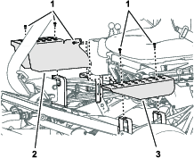
Checking the Hydraulic-Fluid Level
-
Position the machine on a level surface.
Note: Ensure that the machine has cooled down so the fluid is cold.
-
Check the fluid level according to the tank on your machine:
-
If the auxiliary hydraulic tank has a sight window, check the oil level there (Figure 55), and proceed to step 5.
Note: If the fluid level is between the 2 marks on the sight window, the fluid level is sufficient.
-
If the auxiliary hydraulic tank does not have a sight window, locate the dipstick on the top of the machine (Figure 55) and proceed to step 3.
-
-
Remove the dipstick and wipe it with a clean rag, then screw the dipstick back into the tank.
-
Remove the dipstick and check the fluid level. If it is between the marks on the dipstick, the level is sufficient. If the fluid level is not between the marks, adjust the fluid level accordingly (Figure 56).
-
Remove the cap from the hydraulic fluid tank and slowly fill the tank with the appropriate high quality hydraulic fluid until the level is between the 2 marks on the sight window or dipstick.
Important: To prevent system contamination, clean the top of the hydraulic-fluid containers before puncturing them. Ensure that the pour spout and funnel are clean.
Note: Do not mix hydraulic fluids.
-
Install the cap.
Note: Make a close visual inspection of the hydraulic components. Inspect them for leaks, loose fasteners, missing parts, or improperly routed lines. Make any necessary corrections.
Changing the Hydraulic Fluid and Filter
| Maintenance Service Interval | Maintenance Procedure |
|---|---|
| Every 800 hours |
|
| Every 1,000 hours |
|
| Every 2,000 hours |
|
Hydraulic Fluid Capacity: 25.7 L (6.8 US gallons)
If the fluid becomes contaminated, have your authorized Toro distributor flush the system. Contaminated fluid looks milky or black when compared to clean fluid.
-
Clean the area around the filter mounting area (Figure 57). Place a drain pan under the filter and remove the filter.
Note: If you will not be draining the fluid, disconnect and plug the hydraulic line going to the filter.
-
Fill the replacement filter with the appropriate hydraulic fluid, lubricate the sealing gasket, and hand turn it until the gasket contacts the filter head. Then tighten it 3/4 turn further.
-
Fill the hydraulic reservoir with hydraulic fluid; refer to Hydraulic Fluid Specifications and Checking the Hydraulic-Fluid Level.
-
Start the machine and run it at idle for 3 to 5 minutes to circulate the fluid and remove any air trapped in the system. Shut off the engine and check the fluid level.
-
Dispose of the fluid and filter properly.
Checking the Hydraulic Lines and Hoses
| Maintenance Service Interval | Maintenance Procedure |
|---|---|
| Before each use or daily |
|
Check the hydraulic lines and hoses daily for leaks, kinked lines, loose mounting supports, wear, loose fittings, weather deterioration, and chemical deterioration. Make all necessary repairs before operating.
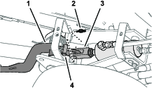
Checking the Leak Detector
The leak detector system is designed to assist in early detection of hydraulic-fluid-system leaks. If the fluid level in the main hydraulic reservoir is lowered by 118 to 177 ml (4 to 6 oz), the float switch in the tank will close. After a 1 second delay, the alarm sounds, alerting the operator (Figure 60). Expansion of fluid, due to normal heating during machine operation, causes the fluid to transfer into the auxiliary fluid reservoir. The fluid returns to the main tank when you turn off the ignition switch.
Checking the System Operation
-
With ignition switch in the ON position, move the leak detector switch rearward and hold. After the 1-second delay elapses, the alarm should sound.
-
Release the leak-detector switch.
Checking the Leak-Detector-System Operation
-
Move the ignition switch to the ON position. Do not start the engine.
-
Remove the hydraulic-tank breather from the neck of the tank.
-
Insert a clean rod or screwdriver into the tank neck and gently push down on the switch float (Figure 61); the alarm should sound after the 1-second delay.
-
Release the float; the alarm should stop sounding.
-
Install the hydraulic-tank cap.
-
Move the ignition switch to the OFF position.
Operating the Leak Detector
The leak detector alarm may sound for 1 of the following reasons:
-
A leak of 118 to 177 ml (4 to 6 oz) has occurred.
-
The fluid level in the main reservoir is reduced by 118 to 177 ml (4 to 6 oz) due to contraction of the fluid by cooling.
If the alarm sounds, turn off the machine as quickly as possible and inspect it for leaks. If the alarm sounds while operating on a green, drive off the green first. Determine the source of the leak and repair it before continuing operation.
If you do not find a leak and suspect a false alarm, move the ignition switch to the OFF position and allow the machine to stand for 1 to 2 minutes to allow the fluid levels to stabilize. Then start the machine and operate it in a non-sensitive area to confirm that no leak exists.
False alarms, due to fluid contraction, may be caused by extended idling of the machine after normal operation. A false alarm may also occur if you work the machine at a reduced workload after an extended period of a heavier workload. To avoid false alarms, turn the machine off rather than idling for extended periods.
Cutting Unit Maintenance
Blade Safety
Refer to and complete the procedure in Maintenance Safety. A worn or damaged blade or bedknife can break, and a piece could be thrown toward you or bystanders, resulting in serious personal injury or death.
-
Inspect the blades and bedknives periodically for excessive wear or damage.
-
Use care when checking the blades. Wear gloves and use caution when servicing them. Only replace or backlap the blades and bedknives; never straighten or weld them.
-
On machines with multiple cutting units, take care when rotating a reel; it can cause the reels in the other cutting units to rotate.
Checking the Reel-to-Bedknife Contact
| Maintenance Service Interval | Maintenance Procedure |
|---|---|
| Before each use or daily |
|
Each day before operating the machine, check the reel-to-bedknife contact, regardless if the quality of cut had previously been acceptable. There must be light contact across the full length of the reel and bedknife; refer to the Cutting Unit Operator’s Manual.
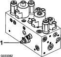
Setting the Reel Speed
To achieve a consistent, high-quality cut and a uniform after-cut appearance, you must correctly set the reel speed control (located on the manifold block under the cover to the left of the seat). Adjust the reel speed control as follows:
-
Decide the height of cut at which the cutting units are set.
-
Decide the desired ground speed best suited for conditions.
-
Use table that follows to determine the reel-speed setting for your 5-, 8-, 11-, or 14-blade cutting units (Figure 62).

-
Tilt the operator’s seat forward and support it with the prop rod (Figure 63).
-
To adjust the reel speed by rotating the knob of the reel-speed control (Figure 64) until the indicator arrow are in line with the number that you determined in step 3.
Note: You can increase or decrease the reel speed to compensate for turf conditions.
Backlapping the Reels
Warning
Contact with the reels or other moving parts can result in personal injury.
-
Keep your hands and clothing away from the reels or other moving parts.
-
Never attempt to turn the reels by hand or foot while the engine is running.
-
Position the machine on a level surface, lower the cutting units, shut off the engine, remove the key, and set the parking brake.
-
Tilt the operator’s seat forward and support it with the prop rod (Figure 65).
-
Make initial reel to bedknife adjustments appropriate for honing all the cutting units that you are backlapping; refer to the Cutting Unit Operator's Manual.
-
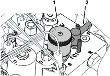
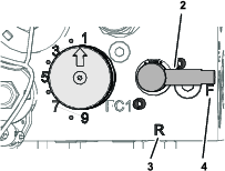
Rotate the backlap lever to the R position (Figure 66).
-
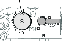
Rotate the reel-speed knob to setting 1 (Figure 66).
-
Start the engine and run at low idle speed.
Important: Do not change the engine speed while backlapping or the reels may stall. Only backlap at idle engine speed.
-
With the mow/transport lever in the NEUTRAL position, move the raise/lower mow control forward to start the backlapping operation on the reel.
-
Apply lapping compound with a long handle brush. Never use a short-handled brush.
-
If the reels stall or become erratic while backlapping, select a higher reel speed setting until the speed stabilizes, then return the reel speed to setting 1 or to your desired speed.
-
To make an adjustment to the cutting units while backlapping, turn the reels off by moving the raise/lower mow control rearward and shut off the engine. After completing adjustments, repeat steps 4 through 8.
-
-
Repeat the steps 4 through 8 for all cutting units that you want to backlap.
-
When finished, return the backlap lever to the F position, move the reel speed knob to the desired reel-speed setting, lower the seat, and wash all lapping compound off of the cutting units. Adjust cutting unit reel to bedknife as needed.
Important: If you do not return the backlap lever to the F position after backlapping, the cutting units will not raise or function properly.
Storage
If you wish to store the machine for a long period of time, the following steps should be performed prior to storage:
-
Shut off the engine, remove the key, wait for all moving parts to stop and allow the machine to cool before storing.
-
Remove accumulations of dirt and old grass clippings. Sharpen the reels and bedknives, if necessary; refer to the Cutting Unit Operator's Manual. Use a rust preventive on bedknives and reel blades. Grease and oil all lubrication points; refer to Greasing the Machine.
-
Block up the wheels to remove any weight on the tires.
-
Drain and replace the hydraulic fluid and filter and inspect the hydraulic lines and fittings. Replace, if necessary; refer toServicing the Hydraulic Fluid and Checking the Hydraulic Lines and Hoses.
-
Drain the fuel tank. Run the engine until it stops from lack of fuel. Replace the fuel filter; refer to Replacing the Fuel Filter.
-
While the engine is still warm, drain the oil from the crankcase. Refill it with fresh oil; refer to Servicing the Engine Oil.
-
Remove the spark plugs, pour one ounce of SAE 30 oil into the cylinders, and crank slowly to distribute the oil. Replace the spark plugs; refer to Replacing the Spark Plugs.
-
Clean dirt and chaff from the cylinder, cylinder head fins, and blower housing.
-
Remove the battery and charge it fully; refer to Servicing the Battery. Either store it on the shelf or on the machine. Leave the cables disconnected if it is stored on the machine. Store the battery in a cool atmosphere to avoid quick deterioration of the charge in the battery.
-
If possible, store the machine in a warm, dry location.