Installation
Preparing the Machine
-
Moving the blade-control switch to the OFF position.
-
Park the machine on a level surface.
-
Move the motion control levers to the PARK position.
-
Move the throttle control to the FAST position.
-
Shut off the engine.
Assembling the Assist Handle
Parts needed for this procedure:
| Assist handle | 1 |
| Pin (grooved) | 1 |
| Washer—6 x 19 mm (3/8 x 3/4 inch) | 1 |
| Retaining ring | 1 |
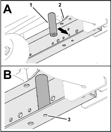
Installing the Support Spacer
Parts needed for this procedure:
| Support spacer | 1 |
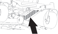
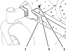
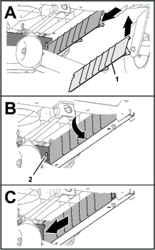
Removing the Rail Guard
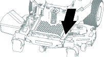
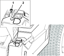
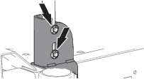
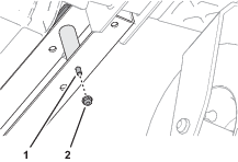
Removing the Floor Pan Screw
Remove the forward button-head screw that secures the flange of the floor pan to the left frame rail (Figure 4).
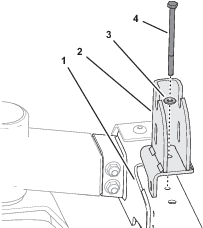
Installing the Assist Handle Bracket
Parts needed for this procedure:
| Assist handle bracket | 1 |
| Capscrew (1/4 x 4 inches) | 1 |
| Washer (1/4 x 5/8 inch) | 1 |
| Flange-head screw (thread forming—5/16 x 3/4 inch) | 1 |
| Flange locknut (1/4 inch) | 1 |
-
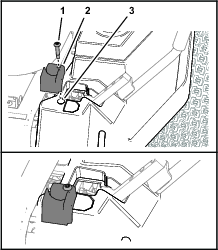
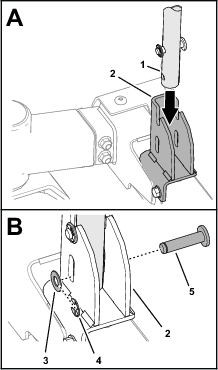
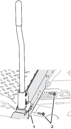
Assemble the assist handle bracket to the left frame rail with the capscrew (1/4 x 4 inches) and washer (1/4 x 5/8 inch) as shown in Figure 8.
Note: Ensure that the capscrew passes through both holes in the frame rail and the hole in the support spacer.
-
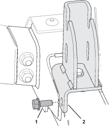
Secure the bracket to the side of the left frame rail (Figure 9) with a flange-head screw ( 5/16 x 3/4 inch).
-
Thread the flange locknut (1/4 inch) onto the capscrew (1/4 x 4 inches), and tighten the nut (Figure 10).
Installing the Assist Handle
Parts needed for this procedure:
| Pin (grooved) | 1 |
| Washer—6 x 19 mm (3/8 x 3/4 inch) | 1 |
| Retaining ring | 1 |
-
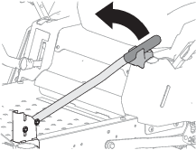
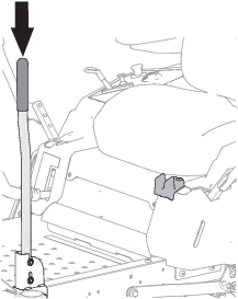
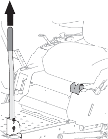
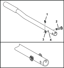
Align the lower hole in the assist handle with the closed slot in the assist handle bracket as shown in Figure 11.
-
Assemble the grooved pin through the slot in the bracket and the hole in the assist handle (Figure 11).
-
Secure the pin to the bracket and handle with the washer—6 x 19 mm (3/8 x 3/4 inch) and the retaining ring (Figure 11).
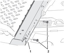
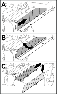
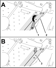
Installing the Rail Guard
-
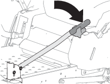
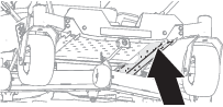
At the bottom of the machine, align the rail guard to the left frame rail, rotate it toward the frame rail, and slide the guard rearward until the tab is fully seated in the slot in the cross brace of the frame (Figure 12).
-
Secure the rail guard to the left frame rail (Figure 13) with the 2 capscrews (1/4 x 5/8 inch).
Installing the Handle Retainer
Parts needed for this procedure:
| Handle retainer | 1 |
| Shoulder screw (1/4 x 1-5/8 inch) | 1 |