The GeoLink™ spray system kit is an attachment for a turf spray application vehicle and is intended to be used by professional, hired operators in commercial applications. It is designed primarily for spraying on well-maintained lawns in parks, golf courses, sports fields, and on commercial grounds.
Visit Toro directly at www.Toro.com for product safety and operation training materials, accessory information, help finding a dealer, or to register your product.
Safety
Warning
Chemical substances used in the spray system may be hazardous and toxic to you, bystanders, animals, plants, soils, or other property.
-
Carefully read and follow the chemical warning labels and safety data sheets (SDS) for all chemicals used and protect yourself according to the chemical manufacturer's recommendations. For example, use appropriate personal protective equipment (PPE), including face and eye protection, gloves, or other equipment to guard against personal contact with a chemical.
-
There may be more than 1 chemical used and information on each chemical should be assessed.
-
Refuse to operate or work on the sprayer if this information is not available.
-
Before working on a spray system, clean the machine ensure that the spray system has been triple rinsed and neutralized according to the recommendations of the chemical manufacturer(s) and that all the valves have been cycled 3 times.
-
Verify that there is an adequate supply of clean water and soap nearby, and immediately wash off any chemicals that contact you.
Installation
Note: Determine the left and right sides of the machine from the normal operating position.
Preparing to Install the Kit
Preparing the Sprayer Tank and Optional Rinse Tank
-
Park the machine on a level surface.
-
Engage the parking brake.
-
Extend the left and right boom sections to the horizontal position.
-
Clean the sprayer; refer to Cleaning the Sprayer in the Operator’s Manual for the machine.
Important: Completely empty the sprayer tank before installing the GeoLink Spray System Finishing Kit.
-
For machines with the optional Tank Rinse Kit, perform the following:
-
Pump the water from the rinse tank into the sprayer tank; refer to Operating the Rinse Kit in the Installation Instructions for the Tank Rinse Kit.
-
Drain the water from the sprayer tank; refer to Cleaning the Sprayer in the Operator’s Manual for the machine.
-
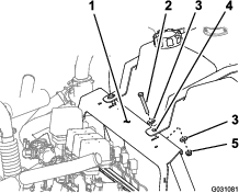
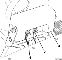
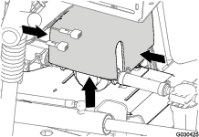
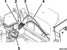
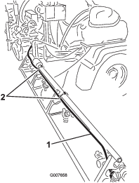
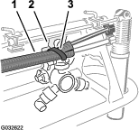
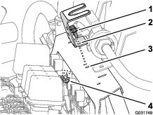
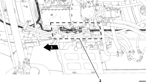
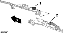
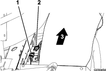
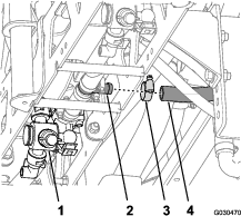
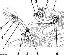
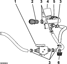
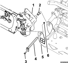
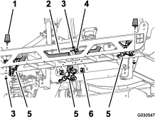
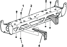
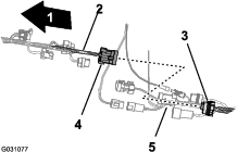
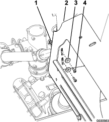
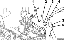
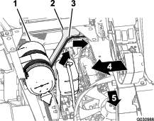
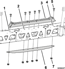
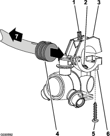
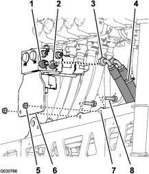
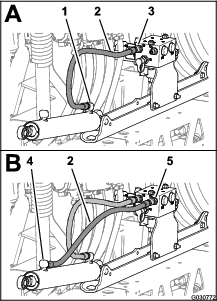
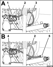
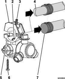
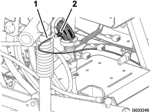
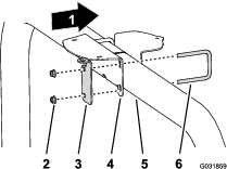
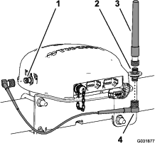
Remove the 2 bolts (3/8 x 2-3/4 inches), 2 flange locknut (3/8 inch), and 4 washers (3/8 inch) that secure the straps for the rinse tank to the manifold mount (Figure 1).
Note: Retain the bolts, nuts, and washers for installation in Installing the Manifold Mount for the 10-Valve System.
-
Secure the rinse tank to the sprayer tank with a piece of rope.
-
Shut off the engine and remove the key.
-
Disconnecting the Battery
Warning
Electrical sparks can cause the battery gasses to explode, resulting in personal injury.
Incorrect battery cable routing could damage the sprayer and cables, causing sparks.
-
Always disconnect the negative (black) battery cable before disconnecting the positive (red) cable.
-
Always connect the positive (red) battery cable before connecting the negative (black) cable.
Battery terminals or metal tools could short against metal sprayer components, causing sparks.
-
When removing or installing the battery, do not allow the battery terminals to touch any metal parts of the sprayer.
-
Do not allow metal tools to short between the battery terminals and metal parts of the sprayer.
-
Always keep the battery strap in place to protect and secure the battery.
-
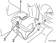
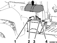
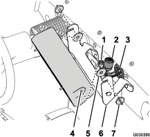
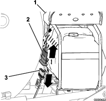
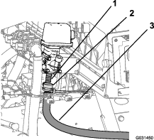
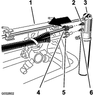
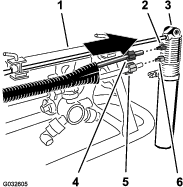
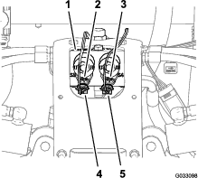
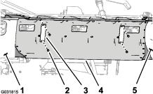
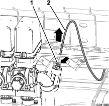
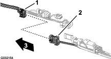
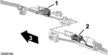
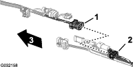
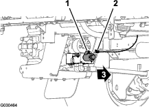
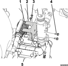
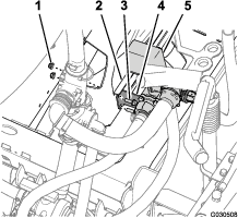
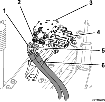
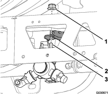
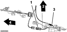
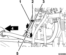
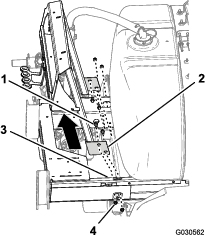
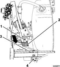
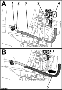
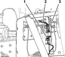
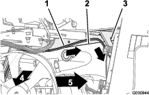
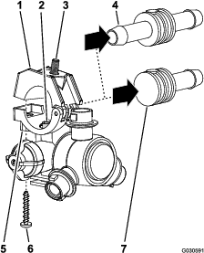
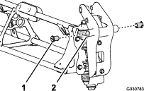
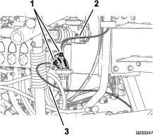
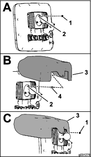
Remove the battery cover and disconnect the negative (black—ground) cable from the battery post (Figure 2 and Figure 3).
-
Disconnect the positive (red) cable from the battery post (Figure 3).
-
Tilt both seats forward and secure them by moving the prop rods into the detents at the end of the slots at the center console base.
-
Allow the engine to cool completely.
Removing the Optional Pro Control XP Spray System
Disconnecting the Flow-Meter Harness
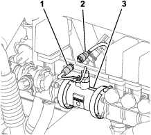
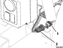
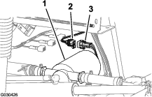
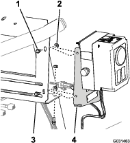
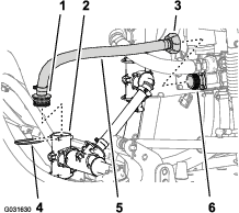
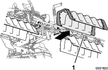
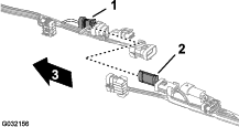
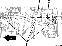
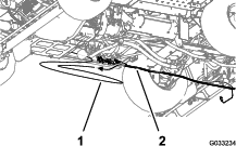
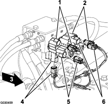
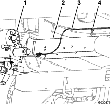
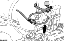
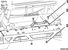
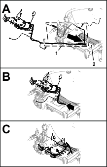
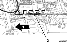
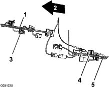
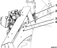
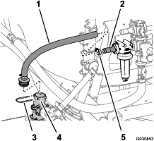
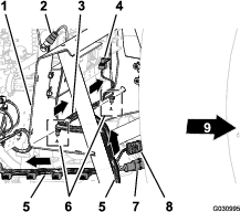
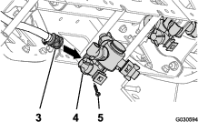
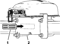
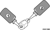
At the back of the machine, remove the 3-socket connector of the machine harness from the 3-pin connector of the flow-meter harness (Figure 4).
Removing the Pro Control Console
-
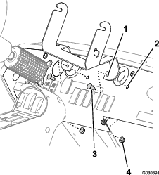
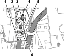
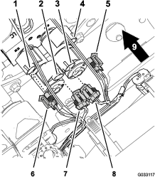
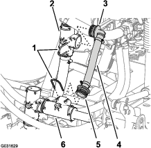
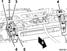
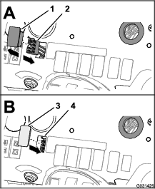
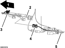
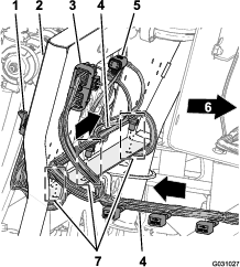
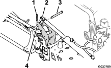
At the front of the pro control console, disconnect the 3-pin connector of the wire harness of the machine from the 3-socket connector of the control console (Figure 5).
-
Disconnect the 16-socket connector from the 16-socket connector of the control console (Figure 5).
-
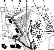
Remove the knobs at each side of the control console (Figure 6).
-
Remove the control console and the 2 rubber washers from the support bracket (Figure 6).
-
Push the harness, the 3-socket connector, and 16-socket connector through the grommet in the dash (Figure 6).
-
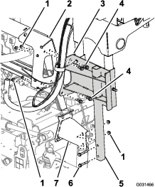
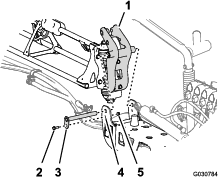
Remove the 2 carriage bolts (5/16 x 3/4 inch) and 2 flange locknut (5/16 inch) that secure the support bracket to the dash panel, and remove the support bracket from the machine (Figure 7).
Note: You no longer need the control console, rubber washers, support bracket, carriage bolts, and locknut that you removed from the machine.
Disconnecting the Rear Wire Harness from the Optional Attachments
Disconnecting the Hand Spray-Wand Kit or the Electric Hose-Reel Kit
Disconnecting the Pivoting Hose-Reel Kit
-
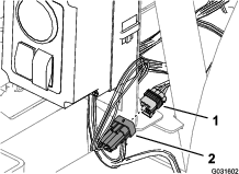
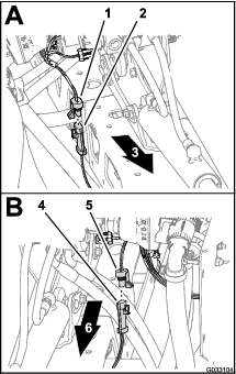
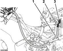
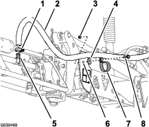
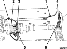
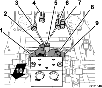
At the back of the machine, locate the wire harness for the pivoting hose-reel kit at the back of the sprayer tank (Figure 10).
-
Disconnect the 2-socket connector of the harness for the electric hose reel from the 2-pin connector of the rear, main harness (Figure 10).
-
Disconnect the 3-pin connector of the harness for the electric hose reel from the 3-pin socket of the rear, main harness (Figure 10).
Disconnecting the Compressor for the Foam Marker Kit
Disconnecting the Control Valve for the Chemical Pre-Mix Kit
Disconnecting the Pump for the Tank Rinse Kit
-
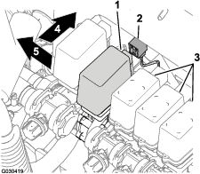
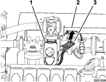
At the back of the machine, press together the sides of the rinse-pump cover and lift the cover up until the tabs of the cover clear the slots in the saddle plate, and remove the cover from the machine (Figure 13).
-
Disconnect the 6-pin connector of the rinse-pump harness from the 6-socket connector of the rear, main harness (Figure 14).
Disconnecting the Optional Hand Spray Wand Kit or Electric Hose Reel Kit
Parts needed for this procedure:
| Switch plug (Electric Hose-Reel Kit—Toro Part No. 99-7420) | 2 |
| Switch plug (Pivoting Hose-Reel Kit—Toro Part No. 99-7420) | 1 |
Removing the Pressure Control and On-Off Switches
-
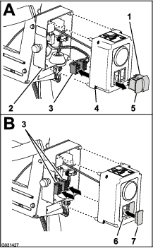
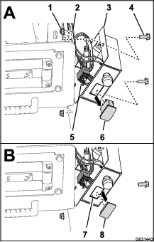
At the control box for the electric hose reel kit, fully loosen the 4 cover screws that secure the cover to the control box and carefully pull out the cover (Figure 15).
-
Remove the switch(s) from the control box as follows:
-
Electric hose reel kit
-
Disconnect the 2 connectors (8-socket) for the control-box harness from the pressure-control switch and the On-Off switch (Figure 15).
-
Route the 2 connectors (8-socket) inside the control box (Figure 15).
-
Squeeze the lock tabs of the 2 switches and press the switches out of the cover for the control box (Figure 15).
Note: You no longer need the switches that you removed from the machine.
-
-
Hand spray wand kit
-
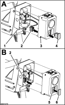
Disconnect the 8-socket connectors for the control-box harness from the pressure-control switch (Figure 16).
-
Route the 8-socket connector inside the control box (Figure 16).
-
Squeeze the lock tabs of the switch and press the switch out of the cover for the control box (Figure 16).
Note: You no longer need the switch that you removed from the machine.
-
-
-
Align the switch plug(s) to the opening(s) in the cover where you removed the switches (Figure 15 and Figure 16).
-
Insert the switch plug(s) into the cover until the plug(s) snap into the cover securely (Figure 15 and Figure 16).
-
Align the cover to the control box and secure the cover to the box with the 4 cover screws (Figure 15).
Disconnecting the Hoses and Tubing
-
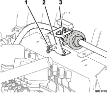
At the 90° elbow at the right side of the pressure-control valve for the hose reel, press in the locking collar for the tube coupler and remove the pressure-sense tube for the pressure gauge of the hose reel (Figure 17).
-
Press in the locking collar for the tube coupler and remove the pressure-sense tube for the pressure gauge in the dash of the machine (Figure 17).
-
Remove the T-fitting from the 90° elbow for the pressure-control valve (Figure 17).
Note: Retain the T-fitting for installation in Installing the Hose and Sense Tubes.
-
Remove the hose clamp that secures the inlet hose for the hose reel to the barbed fitting of the pressure-control valve (Figure 18).
Note: Retain the hose clamp for installation in Assembling the Hose and Fittings.
-
Remove the inlet hose from the hose-reel valve (Figure 18).
Removing the Control Box from the Manifold Mount
-
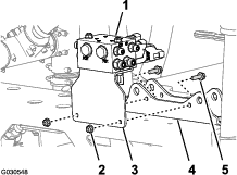
Remove the 3 flange-head bolts (1/4 x 5/8 inch) and 3 serrated-flange nuts (1/4 inch) that secure the mounting plate for the control box to the manifold mount for the sprayer valves (Figure 19).
-
Separate the mounting plate from the manifold mount (Figure 19).
-
Lift the control box from the machine and set the box aside.
Note: Retain all hardware and components for installation in Installing the Control Box to the Manifold Mount.
Disconnecting the Optional Pivoting Hose Reel Kit
Parts needed for this procedure:
| Switch plug (Pivoting Hose Reel Kit—Toro Part No. 99-7420) | 1 |
Removing the Pressure Control Switch
-
Remove the 2 bolt (5/16 x 3/4 inch) and 2 locknut (5/16 inch) that secure the control box to the reel-mounting plate (Figure 20).
-
Disconnect the 8-socket connector for the control box harness from the pressure-control switch (Figure 20).
-
Route the 8-socket connector inside the control box (Figure 20).
-
Squeeze the lock tabs of the pressure-control switch and press the switch out of the control box (Figure 20).
Note: You no longer need the switch that you removed from the machine.
-
Align the switch plug to the opening in the control box where you removed the switch (Figure 20).
-
Insert the switch plug into the control box until the plug snaps into the cover securely (Figure 20).
-
Align the control box to the reel-mounting plate (Figure 20) and secure the box to the plate with the 2 bolt (5/16 x 3/4 inch) and 2 locknut (5/16 inch).
-
Torque the bolts and nuts to 1978 to 2542 N·cm (175 to 225 in-lb).
Disconnecting the Hoses and Tubing
-
At the right end of the pressure-control valve, remove the hose clamp that secures the inlet hose to the barbed fitting of the control valve and remove the hose from the fitting (Figure 21).
Note: Retain the clamp for installation in Installing the Hose and Sense Tubes.
-
Press in the locking collar for the tube coupler and remove the pressure-sense tube for the pressure gauge in the dash of the machine (Figure 21).
-
Press in the locking collar for the tube coupler and remove the pressure-sense tube for the pressure gauge of the hose reel (Figure 21).
-
Remove the T-fitting and tube couplers from the 90° elbow at the end of the pressure-control valve (Figure 21).
Note: Retain the T-fitting and tube couplers for installation in Installing the Hose and Sense Tubes.
Removing the Pivoting-Hose Reel from the Manifold Mount
Lifting equipment capacity: 57 kg (125 lb)
-
Support the pivoting hose reel with lifting equipment with the specified capacity.
-
Remove the 2 flange-head bolts (3/8 x 2-1/4 inches) and 2 flange locknuts (3/8 inch) that secures the lower tube frame of the pivoting hose reel to the mounting bracket at the right frame channel of the machine (Figure 22).
-
Remove the 4 flange-head bolts (3/8 x 1 inch) and 4 flange locknuts (3/8 inch) that secure the support channel of the pivoting hose reel to the manifold mount for the sprayer valves (Figure 22).
-
Lift the pivoting-hose reel from the machine and set the reel aside.
Note: Retain all hardware and components for installation in Installing the Pivoting Hose Reel to the Manifold Mount.
Disconnecting the Optional Foam Marker Kit
Parts needed for this procedure:
| Tube assembly—Toro Part No. 114-9553 | 2 |
| Cable tie | 8 |
Removing the Liquid and Air Tubes from the Machine
-
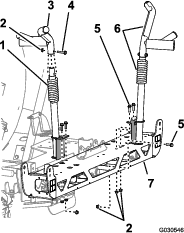
At the connection panel of the compressor for the foam-marker kit, secure a cable tie around the clear and blue tubing for the right boom section (Figure 23).
-
Loosen the compression nuts for the 2 clear and 2 blue tubes for the foam nozzles at the left and right boom sections (Figure 23).
-
Remove the 4 tubes from the compression fittings for the boom sections (Figure 23).
-
At the outer boom section, use a piece of tape to mark the left liquid and air tubes for the left boom section and the right liquid and air tubes for the right boom section.
-
Move the tubes for the foam nozzles at the left and right boom section rearward and through the R-clamp near the pivot point for the boom section (Figure 24).
-
If your machine has the center boom extension kit installed, loosely secure the free end of the liquid and air tubes to the outer boom section, and skip the procedures for Preparing the New Tube Assemblies for the Foam-Marker Nozzles and Installing the New Tube Assembly.
Preparing the New Tube Assemblies for the Foam-Marker Nozzles
-
Remove the cable ties that secure the liquid and air tubes of the foam-marker kit to the outer boom section (Figure 25).
-
At the foam-marker nozzle, loosen the compression nut that secures the blue tube (water) to the blue compression fitting of the foam-marker nozzle (Figure 26).
-
Loosen the compression nut that secures the clear tube (air) to the white compression fitting of the foam-marker nozzle (Figure 26).
-
Remove the liquid and air tubes from the machine.
-
Remove the compression nuts at the ends of the tubes (Figure 26).
Note: Retain the compression nuts for installation in step 1 of Installing the New Tube Assembly.
-
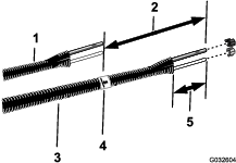
Align the old liquid and air tubes (Figure 27) to the new tube assembly (Toro Part No. 114-9553).
-
Use a piece of tape to mark the length of the old liquid and air tubes onto the new tube assembly.
-
At the new tube assembly, add 26 cm (10 inches) length from the mark that you made in step 7, mark the tube assembly, and cut the tubes at the second (longer) mark (Figure 27).
-
If the old liquid and air tubes are marked with a cable tie, mark the new tube assembly with a cable tie; otherwise skip to step 10.
Note: You no longer need the old liquid and air tubes.
-
Remove 77 to 102 mm (3 to 4 inches) of the sheathing from around each end of the tube assembly (Figure 27).
-
Repeat steps 1 through 10 for the liquid and air tubes at the other side of the machine.
Installing the New Tube Assembly
-
Slip the blue compression nut over the ends of blue tube and the white compression nut over the clear tube (Figure 28).
-
Align the end of the clear tube with the white compression nut to the white fitting of the foam-marker nozzle, and tighten the compression nut by hand (Figure 28).
-
Align the end of the blue tube with the blue compression nut to the blue fitting of the foam-marker nozzle, and tighten the compression nut by hand (Figure 28).
-
Route the tube assembly along the rear side of the upper support pole of the outer boom section as shown in Figure 29.
Important: If you install the tube assembly on the wrong side of the upper support pole, the tubes will be pinched between the cradle and the outer boom section when the booms are in the transport position.
-
Secure the tube assembly to the hole in the nozzle support with a cable tie as shown in Figure 30.
-
Secure the tube assembly to the outer boom section with cable ties as shown in Figure 29.
-
Loosely secure the free end of the tube assembly to the outer boom section.
-
Repeat steps 1 through 6 for the tube assembly at the other side of the machine.
Disconnecting the Optional Ultra Sonic Boom Kit
Disconnecting the Wire Harness at the Lift-Cylinder Manifold
-
Disconnect the 2-pin connector of the sonic boom wire harness from the 2-pin connector of the right cylinder-enable solenoid of the lift-cylinder manifold (Figure 31).
-
Disconnect the 2-pin connector of the sonic boom wire harness from the 2-pin connector of the left cylinder-enable solenoid of the lift-cylinder manifold (Figure 31).
-
Disconnect the 2-socket connectors of the wire harness for the sonic boom finishing kit (Figure 32) from the 2-pin connectors of the solenoids of the lift-cylinder manifold as follows:
Important: Do not remove the sonic boom wire harness from the machine.
-
Left boom section up
-
Right boom section up
-
Left boom section down
-
Right boom section down
-
Disconnecting the Ultra-Sonic Sensor Cable from the Wire Harness
-
Disconnect the 3-socket connector of the sonic boom wire harness from the 3-pin connector of the cable for the right ultra-sonic sensor (Figure 33).
-
Disconnect the 3-socket connector of the sonic boom wire harness from the 3-pin connector of the cable for the left ultra-sonic sensor (Figure 33).
-
Bundle the cables for the ultra-sonic sensors to the left and right boom sections.
Note: Do not remove the sonic boom wire harness from the machine.
Disconnecting the Optional Chemical Pre-Mix Kit
-
Remove the retainer that secures the straight-barbed fitting of the pressure-relief hose to the pressure relief valve for the sprayer system (Figure 34).
Note: Retain the retainers for installation in step 2 of Installing the Pressure Relief-Hose Assembly.
-
Remove the retainer that secures the 90° barbed fitting of the pressure-relief hose to the T-fitting for the supply circuit of the sprayer pump (Figure 34).
Note: Retain the retainer for installation in step 4 of Installing the Pressure Relief-Hose Assembly; you no longer need the 90° fitting, pressure-relief hose, and straight flange fitting that you removed from the machine.
-
Remove the pressure-relief hose and fittings from the machine (Figure 34).
Note: You no longer need the hose and fittings that you removed from the machine.
-
Remove the retainer that secures the straight-barbed fitting of the bypass hose to the T-fitting at the sprayer pump (Figure 35).
-
Loosen the adapter nut at the inboard end of the bypass hose from the adapter fitting of the bypass valve (Figure 35).
-
Remove the hose from the machine (Figure 35).
Note: Retain the retainer for installation in Connecting the Eductor-Supply Hose; you no longer need the hose and fitting that you removed from the machine.
-
Remove the hose clamp that secures the eductor-supply hose to the barbed fitting of the eductor-control valve (Figure 36).
Note: Retain the hose clamp for installation of the eductor-supply hose in step 2 of Connecting the Eductor-Supply Hose.
-
Remove the hose from the eductor-control valve (Figure 36).
Note: Do not remove the eductor-supply hose from the barbed fitting at the eductor.
Disconnecting the Optional EU Compliance Kit
-
Empty the rinse tank; refer to 51 and 52 in Preparing the Sprayer Tank and Optional Rinse Tank.
-
Disconnect the rinse 2 tank straps; refer to step 53 in Preparing the Sprayer Tank and Optional Rinse Tank.
-
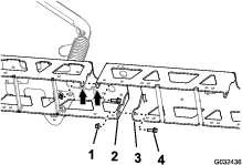
Remove the 2 flange-head bolts (5/16 x 5/8 inch) that secure the ball valve to the mounting bracket for the ball valve (Figure 37).
Note: Retain the bolts for installation in step 5 of Installing the Ball Valve and Mounting Bracket.
-
Remove the 2 flange-head bolts (5/16 x 3/4 inch), and 2 flange locknuts (3/8 inch) that secure the mounting bracket for the ball valve to the manifold mount, and separate the bracket from the mount (Figure 38).
Note: Retain the bolts and nuts for installation in step 2 of Installing the Ball Valve and Mounting Bracket.
Removing the Center Section Cover (11 Nozzle) of the Optional Covered Boom Kit
-
While supporting the center section cover (11 nozzle), remove the 4 flange-head bolts (5/16 x 1-1/4 inches) and 2 cover straps that secure the cover to the cover-support bracket (Figure 39).
-
Remove the center section cover from the machine (Figure 40).
Note: Retain the cover for assembly in Assembling the Optional Covered Boom Kit; retain the cover straps and flange-head bolts for installation in steps 2 and 1 of Installing the Center Section Cover.
-
Remove the 2 flange locknuts (3/8 inch) that secure the left cover-support bracket to the left support bracket for the center boom section, and remove the cover-support bracket (Figure 41).
-
Thread the 2 flange locknuts (3/8 inch) on to the flange-head bolts (3/8 x 1 inch) of the left support bracket for the center boom section (Figure 41) and torque the bolt and nut to 37 to 45 N·m (27 to 33 ft-lb).
-
Repeat steps 3 and 4 for the cover-support bracket and support bracket for the center boom section at the right side of the center boom section (Figure 41).
-
Remove the clip nuts from the left and right cover-support brackets (Figure 41).
Note: Retain the clip nuts for installation in step 1 of Installing the Support Bracket for the Center Section Cover; you no longer need the 2 cover-support brackets.
Disconnecting the Pressure-Sense Tube for the Dash Gauge (for Machines without an Optional Hose Reel Kit)
Note: If your machine is equipped with an optional Hand Spray-Wand Kit, optional Electric Hose-Reel kit, or optional Pivoting Hose-Reel Kit, refer to Disconnecting the Optional Hand Spray Wand Kit or Electric Hose Reel Kit or Disconnecting the Optional Pivoting Hose Reel Kit.
Removing the Optional Undercarriage Shroud Kit
-
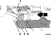
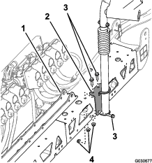
Remove the 7 flange-head bolts (5/16 x 7/8 inch) and 7 washers (5/16 inch) that secure the rear of the undercarriage shroud to the chassis of the machine (Figure 44).
Note: Retain the flange-head bolts and washers for installation in step 5 of Installing the Optional Undercarriage Shroud Kit.
-
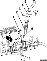
Remove the 4 flange locknuts (5/16 inch) from the bolts and carriage bolt that secure the support straps of the undercarriage shroud to the engine-mount brackets of the machine (Figure 45).
Note: Do not remove the bolts from the machine. Retain the flange locknuts for installation in step 3 of Installing the Optional Undercarriage Shroud Kit.
-
Lift the support straps over the bolts that secure the undercarriage shroud to the engine-mount brackets.
-
Remove the undercarriage shroud from the machine (Figure 44 and Figure 45).
Removing the Rear Wire Harness for the Machine
Parts needed for this procedure:
| Rear wire harness | 1 |
Disconnecting the Front and Rear Wire Harnesses
Note: Use a machine hoist when disconnecting the front and rear wire harnesses.
-
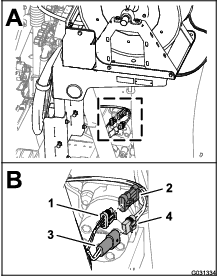
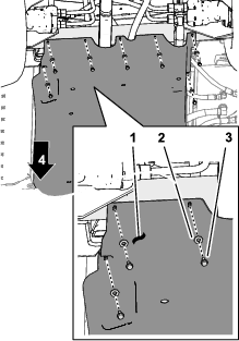
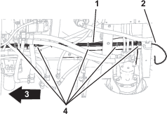
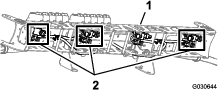
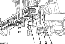
From under the machine along the right frame tube, locate the electrical connectors for the front and rear wire harnesses of the machine (Figure 46).
-
Disconnect the 5 pairs of connectors between the front and rear wire harnesses as shown in Figure 47 through Figure 51.
-
Remove the 3 push-in fasteners that secure the rear wire harness to the holes in the right frame tube of the machine (Figure 52).
-
Remove the pressure-sense tube for the dash gauge from the rear wire harness of the machine (Figure 53).
Disconnecting the Connectors of the Components
-
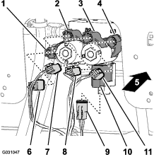
At back of the machine (between the right frame tube and the right fender) disconnect the 3-pin connector of the speed-sensor harness at the right hydraulic-traction motor from the 3-socket connector of the rear, main harness (Figure 54).
-
At the back of the manifold mount, disconnect the 3-socket connector from the agitation valve and the 3-socket connectors from the 3 boom-section valves (Figure 55).
-
Remove the push-in fastener that secures the rear wire harness to the holes at the forward side of the manifold mount (Figure 56).
-
At the back of the machine, disconnect the following 2-socket connectors (Figure 57) for the lift-cylinder manifold as follows:
Note: For machines to the ultra sonic boom kit; refer to Disconnecting the Wire Harness at the Lift-Cylinder Manifold.
-
Right—up solenoid
-
Left—up solenoid
-
Enable solenoid
-
Right—down solenoid
-
Left—down solenoid
-
-
At the back of the machine (inboard of the sprayer pump), disconnect the 2-socket connector of the rear, main harness from the 2-pin connector of the relay for the pump (Figure 58).
-
Remove the push-in fastener that secure the rear wire harness (Figure 59) to the holes in the rear cross tube (rearward of the hydraulic-traction motors).
-
Remove the rear wire harness from the machine.
Note: You no longer need the rear, main harness that you removed from the machine.
Removing the Rate-Control Switch
Parts needed for this procedure:
| Cable tie | 1 |
| Switch plug | 1 |
-
From under the dash panel of the machine, squeeze the lock tabs of the rate-control switch together and push up the rate-control switch out of the dash panel (Figure 60).
-
Disconnect the 8-socket connector of the front harness of the machine (labeled RATE SWITCH) from the 8-pin connector of the switch (Figure 60).
Note: You no longer need the rate switch that you removed from the machine.
-
Route the branch of the front harness for the rate switch through the opening in the dash and secure the wiring branch against the front harness with a cable tie.
-
Align the switch plug to the opening in the dash panel where you removed the rate switch (Figure 60).
-
Insert the switch plug into the dash panel until the plug snaps into the panel securely (Figure 60).
Removing the Boom-Section Valves and the Agitation Valve
Removing the Boom-Section Valves and Hoses
-
At the forward side of the sprayer boom section, remove the R-clamp, shoulder bolt (5/16 inch), washer (5/16 inch), and flange locknut (5/16 inch) that secure the boom hose to the center section frame (Figure 61).
-
Remove the hose clamp and boom hose from the barbed T-fitting (Figure 61).
-
Repeat steps 1 and 2 for the clamp and hose of the sprayer boom section at the other side of the machine.
-
Adjacent to the center sprayer nozzle, remove the hose clamp and boom hose from the barbed T-fitting (Figure 62).
-
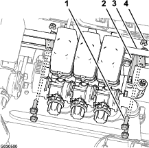
Remove the 4 flange-head bolts (5/16 x 1 inch) and 4 flange locknut (5/16 inch) that secure the mounting brackets at either end of the 3 boom-section valves to the manifold mount (Figure 63).
-
Remove the hose clamp that secures the hose (1 inch inside diameter) to the barbed-elbow fitting and remove the hose from the fitting (Figure 64).
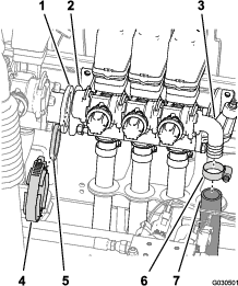
-
Remove the flange clamp and gasket that secure the flange adapter on the agitation valve and the flange adapter on the left boom-section valve (Figure 64).
-
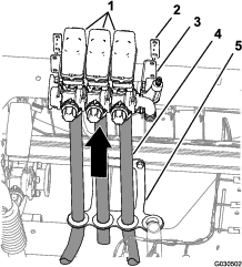
With the 3 boom hose attached to the 3 boom-section valves, carefully lift the valves from the hose loom and remove the valves and hoses from the machine (Figure 65).
Note: If needed, lubricate the hoses with mineral oil as you pull the hoses through the rubber grommets in the loom.
Note: You no longer need the clamps, bolts, locknuts, spacers valves, and hoses that you removed from the machine.
Removing the Agitation Valve, Ball Valve, and Hoses
Danger
Residual sprayer chemicals contained in the hoses and components can injure your eyes and skin.
-
Wear safety glasses or goggles and chemical resistant gloves when disassembling the sprayer system.
-
Carefully disconnect hoses and components when the machine is raised on lifting equipment or you are under the machine.
-
Ensure that the sprayer system is drained through the drain valve.
-
At the left side of the sprayer tank (adjacent to the rear fender), remove the hose clamp and hose (1 inch inside diameter) at the barbed T-fitting of the rear most agitation nozzle (Figure 66).
Note: Retain the hose clamp for installation in step 2 of Installing the Supply Hose for the Agitator Nozzles.
-
At the outlet port for the sprayer pump, remove the retainer and straight-hub fitting from the vertically mounted T-fitting as shown in Figure 66.
Note: Retain the retainers that you removed from the T-fitting for installation in Installing the Supply Hose and Bypass Hose.
-
At the left side of the manifold bracket, remove the retainer and 90° hub fitting from the upper, vertically mounted T-fitting as shown in Figure 66.
Note: Retain the retainers that you removed from the T-fitting for installation in Installing the Supply Hose and Bypass Hose.
-
At the top of the sprayer pump, remove the 2 flange-head bolt (5/16 x 3/4 inch) that secure the ball valve to the valve bracket (Figure 67).
-
Remove the 2 flange-head bolt (1/4 x 3/4 inch) that secure the valve bracket to the mounting bracket on top of the pump (Figure 67).
-
Remove the 2 flanged locknuts (5/16 inch) and 2 flange-head bolts (5/16 x 1 inch) that secure the support bracket for the agitation valve to the manifold mount (Figure 68).
-
Remove the agitation valve (and bypass valve), ball valve, and the hoses that are attached to the valves from the machine (Figure 69).
Disassembling the Agitation and Bypass Valves
-
Remove the hose clamps that secure the hose between the ball valve and the bottom of the agitation valve (Figure 70).
-
Remove the hose clamp that secures the hose to the other end of the ball valve (Figure 70).
-
Remove the hose clamp that secures the 90° barbed fitting to the hose from the bypass valve (Figure 70).
Note: Do not separate the barbed fitting from the hose.
-
Remove the hose clamps that secure the hose between straight-barbed fitting and the agitation valve (Figure 70).
Note: Do not separate the barbed fitting from the hose.
Note: Retain the hose clamps for installation in Installing the Supply Hose for the Agitator Nozzles and Installing the Supply Hose and Bypass Hose.
Note: You no longer need the agitation valve, ball valve, 90° barbed fitting, straight-barbed fitting, and hoses that you removed from the machine.
Removing the Boom Sections
Parts needed for this procedure:
| Cable tie | 1 |
Removing the Lift Cylinders
Note: Except where noted, retain all hardware that you remove.
-
Use lifting equipment of the specified capacity to support the outer boom section.
-
At the back of the machine, remove the hydraulic hoses from between the boom-lift manifold and the hydraulic cylinder (Figure 71).
Note: Protect the boom-lift manifold and the hydraulic cylinder from dust and debris by plugging extend and retract ports.
Note: Discard the hydraulic hoses.
-
Remove the hairpin and clevis pin that secure the rod end of the lift cylinder to the pivot bracket (Figure 72).
Note: Retain the clevis pin and hairpin for installation in Assembling the Outer Boom Sections to the Machine.
-
Remove the flange locknut (5/16 inch) and flange-head bolt (5/16 x 3/4 inch) that secures the pivot pin to the cylinder mount (Figure 73).
-
Remove the pivot pin and the lift cylinder from the machine (Figure 73).
-
Repeat steps 3 and 4 for the lift cylinder at the other side of the machine.
Removing the Outer Boom Sections
Lift equipment capacity: 91 kg (200 lb)
Note: If your machine is equipped with the optional Covered-Boom Kit, leave the covers installed at the outer boom sections.
Warning
Lifting heavy machines and attachments improperly could result in serious injury or even death.
When lifting heavy machines and attachments, use lifting equipment, such as chains and straps, that is rated for the weight of the equipment.
Note: Except where noted, retain all hardware that you remove; you will use the hardware to install the center boom extension.
-
Remove the flange bolt (5/16 x 1 inch) and flange locknut (5/16 inch) securing the pivot pin to the pivot bracket (Figure 74).
-
Remove the pivot pin from the pivot bracket for the center boom section and the pivot fitting for the outer boom section (Figure 74).
Note: Retain the flange bolt, flange nut and pivot pin for installation in Assembling the Outer Boom Sections to the Machine.
-
Separate the outer boom section from the center boom section and remove outer section from the machine (Figure 74).
-
Remove the 2 nylon-flange bushings from the pivot fitting of the outer boom section (Figure 74).
Note: Discard the bushings.
-
Repeat steps 1 through 4 in Removing the Lift Cylinders for the outer boom section at the other side of the machine.
-
Repeat steps 1 through 4 of this section for the outer boom section at the other side of the machine.
Removing the Lift Cylinder Manifold and Support Bracket
-
At port P of the boom-lift manifold, mark the pressure hydraulic hose with a cable tie (Figure 75).
-
Disconnect hydraulic pressure and return hoses from the boom-lift manifold (Figure 75).
Important: Elevate the free ends of the hydraulic-return hose and hydraulic-pressure hose to avoid draining the hydraulic tank.
-
Remove the 2 flange locknuts (5/16 inch) and 2 flange-head bolts (5/16 x 1 inch) that secure the support bracket for the boom-lift manifold to the cylinder mount, and remove the manifold and bracket from the machine (Figure 76).
Removing the Boom Cradle
-
At the left boom cradle, remove the flange-head bolt (3/8 x 2 inches) and flange locknut (3/8 inch) that secure the left upper cradle assembly to the lower cradle assembly (Figure 77).
Note: Retain the upper cradle, bolt, and nut for installation in Assembling the Cradles to the Center Boom Section.
-
Remove the 3 flange-head bolt (3/8 x 2 inches) and 3 flange locknut (3/8 inch) that secure the left lower boom cradle to the frame of the center boom section, and remove the cradle (Figure 77).
Note: Retain the 3 flange-head bolt (3/8 x 2 inches) and 3 flange locknut (3/8 inch) for installation of the new left lower boom cradle onto the new center boom section in Assembling the Cradles to the Center Boom Section.
Note: You no longer need the left lower boom cradle that you removed from the machine.
-
At the right cradle, remove the horizontal and 2 vertical flange-head bolt (3/8 x 1-1/4 inches) and 3 flange locknut (3/8 inch) that secure the right boom-cradle assembly to the frame of the center boom section (Figure 77).
Note: Retain the right cradle assembly, flange-head bolts, and flange locknuts for installation in Assembling the Cradles to the Center Boom Section.
-
Remove flange locknuts (5/16 inch) that secure the left and right bumpers at the ends of the frame of the center boom section (Figure 78).
Note: Retain the bumpers and locknuts for installation.
Removing Sprayer Nozzles
-
Remove 4 hose clamps that secure the 3 sprayer nozzles to the hoses (3/4 inch inside diameter (Figure 78).
-
Remove the flange locknut (5/16 inch) that secure the 3 sprayer nozzles to the nozzle mounts of the center boom section, and remove the nozzles (Figure 78).
Note: Retain the sprayer nozzles and flange locknuts for installation in Installing the Nozzles in the New Center Boom Section.
-
Remove 2 carriage bolts (1/2 x 1-1/4 inches) and 2 flange locknuts (1/2 inch) that secure the cylinder mount to the center boom section and remove the mount (Figure 80).
Note: You no longer need the cylinder mount that you removed from the machine.
Note: Retain the carriage bolts, flange locknuts, hoses, and clamps for installation in Assembling the Center-Boom Section Trusses.
Removing the Center Boom Section
-
If your machine is equipped with the optional Covered Boom Kit, remove the cover from the center boom sections.
-
Support the center boom section with lifting equipment.
-
Remove the 4 flange-head bolts (1/2 x 1-1/4 inches) and 4 flange locknuts (1/2 inch) that secure the support brackets of the center boom section to the mounting channel on the frame for the sprayer, and remove the center boom section from the machine (Figure 81).
Note: Retain the bolts (1/2 x 1-1/4 inches) and locknuts (1/2 inch) for installation of the new center boom section.
-
Remove the 2 flange-head capscrews (3/8 x 1 inch) and 2 flange locknuts (3/8 inch) that secure the support bracket to the center boom section, and remove the bracket (Figure 82).
-
Repeat step 4 for the other support bracket (Figure 82).
Note: Retain the flange-head capscrews (3/8 x 1 inch) and flange locknuts (3/8 inch) for installation in Assembling the Center-Boom Section Trusses. You no longer need the center boom section and support brackets.
Assembling the Rear Wire Harness to the Machine
Parts needed for this procedure:
| Rear wire harness | 1 |
| Cable ties | 5 |
Routing Wire Harness Along the Frame Tube
-
Locate the 165 cm (65 inches) branch and the 203 cm (80 inches) branch of the new electrical harness (Figure 83).
-
Route the 180 cm (71 inches) branch, 108 cm (42-1/2 inches) branch, and the 127 cm (50 inches) branch of the new electrical harness under the frame channel (Figure 84).
-
Route the 180 cm (71 inches), 108 cm (42-1/2 inches), and the 127 cm (50 inches) branches of the electrical harness forward along the right frame tube (Figure 85).
-
Insert the push-in anchors of the 127 cm (50 inches) branch of the rear wire harness into the holes in the right frame tube (Figure 85) where the fir trees of the old rear harness where removed; refer to step 3 in Disconnecting the Front and Rear Wire Harnesses.
Connecting the Front and Rear Wire Harnesses
Note: Use a hoist the raise the machine when connecting the front and rear wire harnesses.
-
From under the machine along the right frame tube, locate the electrical connectors for the front and rear wire harnesses of the machine (Figure 86).
Note: You will not use the 3-socket connector of the front harness and the 2-socket connector of the rear harness (Figure 87).
-
Connect the 10-socket connector of the front harness for the sprayer-harness interconnect into the 10-pin connector of the rear harness for the sprayer-harness interconnect (Figure 88).
-
Connect the 8-pin connector of the front harness for the sprayer-harness interconnect into the 8-socket connector of the rear harness for the rate switch (Figure 89).
-
Connect the 2-pin connector of the front harness for the rinse pump into the 2-socket connector of the rear harness for the rinse pump (Figure 90).
-
Connect the 10-pin connector of the front harness for the sprayer-harness interconnect into the 10-socket connector of the rear harness for the sprayer-harness interconnect (Figure 91).
-
To ease connecting the navigation-electrical and data harnesses, ensure that the 1-socket connector of the rear wire harness and the 4-socket connector of the rear wire harness are aligned to the top of the harness (Figure 92).
Routing the Pressure-Sense Tube
-
Route the pressure-sense tube for the dash gauge along the rear wire harness (Figure 93).
-
Secure the tube to the harness with 5 cable ties.
Routing the Wire Harness for the Sprayer Pump
-
Route the 86.6 cm (34 inches) wire harness branch for the spray-pump solenoid across the top of the sprayer frame channel and down toward the sprayer pump solenoid (Figure 94).
-
Insert the push-in fastener of the 86.6 cm (34 inches) wire harness branch into the hole in the sprayer frame channel (Figure 94).
Connecting the Wire Harness to the Sprayer Pump and the Speed Sensor
-
At the back of the machine—inboard of the sprayer pump, connect the 2-socket connector labeled Spray Pump Solenoid of the 86.6 cm (34 inches) wire harness branch into the 2-pin connector of the relay for the pump (Figure 95).
-
At back of the machine (between the right frame tube and the right fender) connect the unlabeled 3-pin connector of the 30.5 cm (12 inches) branch of the rear wire harness to the 3-socket connector of the right traction motor speed-sensor harness (Figure 96).
Removing the Manifold Mount for the 3-Boom Section System
-
Remove the 2 pan-head screws (#10 x 5/8 inch) and 2 washer (#10) that secure the T-fitting to the left side of the manifold mount (Figure 97).
Note: Retain the screws and washers for installation in Installing the Manifold Mount for the 10-Valve System.
-
For machines with the optional Tank-Rinse Kit, perform the following:
-
Remove the bolts (3/8 x 2-3/4 inches), flange locknut (3/8 inch), and washers (3/8 inch) that secure the straps for the rinse tank to the manifold mount (Figure 98).
Note: Retain the bolts, nuts, and washers for installation in Installing the Manifold Mount for the 10-Valve System.
-
Secure the rinse tank to the sprayer tank with a piece of rope.
-
-
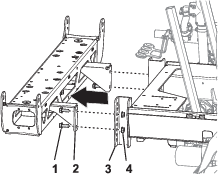
Remove the 4 flange-head bolt (3/8 x 1 inch) and 4 flange-locknut (3/8 inch) that secure the flange of the manifold mount to the frame of the sprayer chassis, and remove the manifold mount from the machine (Figure 99).
Note: Retain the bolts and locknuts for installation in Installing the Manifold Mount for the 10-Valve System.
Note: You no longer need the old manifold mount that you removed from the machine.
Installing the Manifold Mount for the 10-Valve System
Parts needed for this procedure:
| Manifold mount (10-valve system) | 1 |
-
Align the holes in the flange of the manifold mount for the 10-valve system with the holes in the frame of the sprayer chassis (Figure 100).
-
Assemble the manifold mount to the sprayer chassis (Figure 100) with the 4 flange-head bolt (3/8 x 1 inch) and 4 flange-locknut (3/8 inch) that you removed in step 3 in Removing the Manifold Mount for the 3-Boom Section System.
-
Torque the bolts and nuts to 37 to 45 N·m (27 to 33 ft-lb).
-
At the left side of the manifold mount, align the holes in the T-fitting with the slots in the manifold mount (Figure 101).
-
Secure the T-fitting to the manifold mount (Figure 101) with the 2 pan-head screws (#10 x 5/8 inch) and 2 washer (#10) that you removed in step 1 of Removing the Manifold Mount for the 3-Boom Section System.
-
For machines with the optional Tank-Rinse Kit, perform the following:
-
Align the hole in the rinse-tank strap with the hole in the manifold mount (Figure 102).
-
Assemble the strap to the mount (Figure 102) with the 2 bolts (3/8 x 2-3/4 inches), 4 washers (3/8 inch), and 2 flange locknuts (3/8 inch) that you removed in step 53 of Preparing the Sprayer Tank and Optional Rinse Tank.
-
Tighten the bolt and locknut by hand (Figure 102).
Note: Once the rinse tank has been initially filled the rinse tank strap fasteners should be checked and tightened if necessary as the weight of the liquid can further seat the tank against the frame.
-
Repeat steps 1 through 3 for the rinse-tank strap at the other side of the machine.
-
Installing the Hoses at the Left Side of the Manifold Mount
Parts needed for this procedure:
| Hose (1 x 41 inches) | 1 |
| Supply hose (1 x 23-1/8 inches) and straight-barbed fitting | 1 |
| Agitation bypass hose (1 x 10 inches) and 90° barbed fitting | 1 |
Installing the Supply Hose for the Agitator Nozzles
-
Assemble the hose (1 x 41 inches) to the barbed T-fitting at the rear agitation nozzle in the sprayer tank (Figure 103).
-
Secure the hose to the T-fitting with the clamp (Figure 103) that you removed in step 2 of Removing the Agitation Valve, Ball Valve, and Hoses.
-
Assemble the other end of the hose (1 x 41 inches) onto the straight barbed fitting at the bottom of the bypass valve (Figure 103).
-
Secure the hose to the straight fitting with a hose clamp (Figure 103) that you removed in Disassembling the Agitation and Bypass Valves.
-
Assemble the convoluted tubing (Figure 103) over the hose (1 x 41 inches).
Installing the Supply Hose and Bypass Hose
Note: If your machine has the optional Chemical Pre-Mix Kit, skip the instructions in this section and preform the steps in Installing the Supply-Hose Assembly and Replacing the Bypass Hose for the Agitation Valve.
-
Assemble the hub of the straight-barbed fitting at the end of the supply hose (1 x 23-1/8 inches) into the T-fitting at the outlet port for the sprayer pump (Figure 104) with the retainer that you removed in step 3 of Removing the Agitation Valve, Ball Valve, and Hoses.
-
Assemble the supply hose (1 x 23-1/8 inches) with the straight-barbed fitting onto the straight-barbed fitting in the filter head (Figure 104).
-
Secure the hose the barbed fitting with a clamp that you removed in Disassembling the Agitation and Bypass Valves.
-
Rotate the upper T-fitting at the left side of the manifold bracket 90° counterclockwise as shown in Figure 105.
-
Assemble the agitation bypass hose (1 x 10 inches) onto the straight-barbed fitting of the agitation-bypass valve (Figure 105).
-
Assemble the hub of the 90° barbed fitting at the end of the agitation bypass hose (1 x 10 inches) into the upper T-fitting at the left side of the manifold bracket (Figure 105) with the retainer that you removed in step 4 of Removing the Agitation Valve, Ball Valve, and Hoses.
-
Secure the agitation bypass hose (1 x 10 inches) to the straight-barbed fitting of the agitation-bypass valve with a hose clamp that you removed in Disassembling the Agitation and Bypass Valves.
Installing the Rear Wire Harness
Routing the Wire Harness at the Manifold Mount
-
Route the 218.4 cm (86 inches) branch of the wire harness inboard of the support strut for the valve mount and rearward toward the 10-valve mount as shown in Figure 106.
-
Route the 75.5 cm (31 inches) wire harness branch for the flow meter and agitation valve across the front of the manifold mount (Figure 106).
-
Insert the push-in fasteners of the 75.5 cm (31 inches) wire harness branch into the holes in the lower flange of the manifold mount (Figure 106).
Routing the Wire Harness at the 10-Valve Mount
-
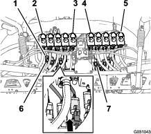
Route the 218.4 cm (86 inches) wire harness branch across the back of the 10-valve mount with the 10 connectors for the nozzle valves rearward and below the valves (Figure 107).
-
Insert the push-in fasteners of the 218.4 cm (86 inches) wire harness branch into the holes in the lower flange of the 10-valve mount (Figure 107).
Connecting the Wire Harness to the Manifold Mount Components
-
Route the connectors of the 218.4 cm (86 inches) and 75.5 cm (31 inches) wire harness branchs labeled Flow Meter and labeled Pressure Transducer rearward of the manifold mount (Figure 108).
-
Connect the 3-socket connector of the 75.5 cm (31 inches) wire harness branch for the flow meter (not labeled) into the 3-pin connector of the harness of the flow meter (Figure 108).
-
Connect the 3-socket connector of the 218.4 cm (86 inches) wire harness branch for the labeled Pressure Transducer into the 3-pin connector of the pressure transducer (Figure 108).
-
Adhere the magnet-harness anchors for the flow meter and the pressure transducer onto the surface of the manifold mount (Figure 108).
-
Route the 3-pin connector for the harness of the agitation valve forward of the manifold mount (Figure 109).
-
Connect the 3-pin connector for the harness of the agitation valve into the 3-socket connector of the 203 cm (80 inches) wire harness branch labeled Agitation Valve (Figure 110).
Connecting the Wire Harness to the Solenoids for the Lift-Cylinder Manifold
-
At the bottom of the lift-cylinder manifold, connect the 2-socket connector of the rear wire harness labeled Enable Solenoid into the 2-pin connector for the enable solenoid (Figure 111 and Figure 112).
-
At the lower right solenoid, connect the 2-socket connector of the rear wire harness labeled Right Down into the 2–pin connector for the right down solenoid (Figure 111 and Figure 112).
-
At the upper right solenoid, connect the 2-socket connector of the rear wire harness labeled Right Up into the 2–pin connector for the right up solenoid (Figure 111 and Figure 112).
-
At the lower left solenoid, connect the 2-socket connector of the rear wire harness labeled Left Down into the 2–pin connector for the left down solenoid (Figure 111 and Figure 112).
-
At the upper left solenoid, connect the 2-socket connector of the rear wire harness labeled Left Up into the 2–pin connector for the left up solenoid.
Connecting the Wire Harness to the Sprayer Valves
-
Route the 3-socket connectors of the 218.4 cm (86 inches) wire harness branch with labels Nozzle Valve 1 through Nozzle Valve 5 rearward of the 10-valve mount and below nozzle valves 1 through 5 (Figure 113).
-
Route the 3-socket connectors of the 218.4 cm (86 inches) wire harness branch with labels Nozzle Valve 6 through Nozzle Valve 10 rearward of the 10-valve mount and below nozzle-valves 6 through 10 (Figure 113).
-
Connect the 3-pin socket connector of the rear wire harness labeled Nozzle 1 to the 3-pin connector of the harness for nozzle-valve 1 (Figure 113).
Important: It is important that you connect each labeled 3-pin socket connector of the rear wire harness to the correct 3-pin connector at each nozzle-valve position.
-
Repeat step 3 at the nozzle-valve positions 2 through 10 (Figure 113).
Routing the Wire Harness through the Engine Compartment
-
Route the 108 cm (42-1/2 inches) branch of the wire harness up and into the rear part of the engine compartment, along the right support for the engine shroud—forward of the duct that connects the air filter and the engine (Figure 114).
Note: You will secure the 108 cm (42-1/2 inches) branch of the rear wire harness in Routing the Navigation Electrical Harness to the Battery.
-
Route the 108 cm (42-1/2 inches) branch of the wire harness across the seat-box angle and down along the left support for the engine shroud (Figure 115).
Note: You will secure the 108 cm (42-1/2 inches) branch of the rear wire harness in Routing the Navigation Electrical Harness to the Battery.
-
Route the 108 cm (42-1/2 inches) branch of the wire harness down along the left support for the engine shroud and under the left frame tube (Figure 116).
Note: You will secure the 108 cm (42-1/2 inches) branch of the rear wire harness in Routing the Navigation Electrical Harness to the Battery.
-
Route the 50 A fuse and the positive and negative ring terminals of the 108 cm (42-1/2 inches) branch of the wire harness to the top of the battery (Figure 116).
Note: You will complete the installation of the ring terminals in Assembling the Rear Harness and Navigation Electrical Harness to the Battery Cables.
Preparing the New Center Boom Section
Parts needed for this procedure:
| Outer center-section truss frame (left—long) | 1 |
| Center-section truss frame (middle—short) | 1 |
| Outer center-section truss frame (right—long) | 1 |
| Flange-head capscrew (3/8 x 1 inch) | 4 |
| Flange locknut (3/8 inch) | |
| Lower cradle assembly | 1 |
Assembling the Center-Boom Section Trusses
-
Align the holes in vertical flanges of the middle center-section truss frame with the holes in the outer center-section truss frame (Figure 117).
-
Loosely assemble the center-boom extension to the truss frame (Figure 117) with the 2 flange-head bolts (3/8 x 1 inch) and 2 flange locknuts (3/8 inch).
-
Align the holes in vertical flanges of the middle center-section truss frame with the holes in the other outer center-section truss frame (Figure 117).
-
Loosely assemble the center-boom extension to the other truss frame (Figure 117) with the 2 flange-head bolts (3/8 x 1 inch) and 2 flange locknuts (3/8 inch).
-
Align the holes in the cylinder mount with the holes at the centerline of the middle truss frame (Figure 118).
-
Insert the stiffener channel into the center and outer truss frames and align the hole in the channele with the holes at the centerline of the middle truss frame (Figure 118).
-
Assemble the cylinder mount, trusses, center-boom extension, and stiffener channel with the 2 carriage bolt (1/2 x 1-1/4 inches) and 2 flange locknut (1/2 inch) that you removed in step 3 of Removing Sprayer Nozzles, and the 4 carriage bolt (1/2 x 1-1/4 inches) and 4 flange locknut (1/2 inch) from the GeoLink spray system finishing kit (Figure 118).
-
Torque the 3/8 inch flange head bolts and flange locknuts to 37 to 45 N∙m (27 to 33 ft-lb).
-
Torque the 1/2 inch flange locknuts to 91 to 113 N∙m (67 to 83 ft-lb).
Installing the Nozzles in the New Center Boom Section
-
Using lifting equipment, raise the new center boom section to a comfortable working height.
-
Working with the 3 sprayer nozzles that you removed in step 1 in Removing Sprayer Nozzles, remove the stainless steel screw (#12 x 1-1/4 inches) that secures the upper clamp half and double or single barbed-hose shank (3/4 inch) to the body of each of the sprayer nozzle, and remove the barbed-hose shanks (Figure 119).
Note: The hex-head bolt (5/16 x 3/4 inch—stainless steel) separates from the upper clamp half when you open the clamp; retain the bolt for installation.
-
At the center boom section, align the transfer tube in the saddle of a sprayer nozzle (Figure 120 and Figure 121) with the hole in the side of the single barbed-hose shank (1/2 inch).
-
Close the upper clamp half around the barbed-hose shank and secure the clamp half and spray-nozzle body (Figure 121) with the stainless steel screw (#12 x 1-1/4 inches).
Note: Ensure that the hex-head bolt (5/16 x 3/4 inch) is seated in the recess in the upper clamp half when closing the clamp.
-
Assemble the nozzle to the nozzle mount (Figure 79) with the flange locknut (5/16 inch) that you removed in step 2 in Removing Sprayer Nozzles.
-
Torque the flange locknut to 1978 to 2542 N·cm (175 to 225 in-lb).
-
Repeat steps 3 through 6 to the 2 other sprayer nozzles at the 2 other single barbed-hose shanks (1/2 inch).
Assembling the Cradles to the Center Boom Section
-
Align the holes in the mounting bracket of the right boom cradle that you removed in step 3 in Removing the Boom Cradle with the holes at the top and back sides (to the right of the cylinder mount) of the new center boom section (Figure 122).
-
Assemble the right boom cradle to the center boom section with the 3 flange-head bolt (3/8 x 1-1/4 inches) and flange locknuts that you removed in step 3 in Removing the Boom Cradle.
-
Torque the bolts and nuts to 37 to 45 N·m (27 to 33 ft-lb).
-
Align the holes in the mounting bracket of the new left lower boom cradle with the holes at the top and front sides (to the left of the manifold mount) of the new center boom section (Figure 123).
-
Assemble the boom cradle to the center boom section with the 3 flange-head bolts and 3 flange locknuts that you removed in step 2 in Removing the Boom Cradle.
-
At the left lower cradle, assemble the upper cradle that you removed in step 1 in Removing the Boom Cradle onto the lower cradle (Figure 123) with the flange-head bolt (3/8 x 2 inches) and flange locknut (3/8 inch).
-
Assemble the upper, left boom cradle that you removed in step 1 in Removing the Boom Cradle onto the lower cradle with the 3 flange-head bolt (3/8 x 1-1/4 inches) and flange locknut (3/8 inch).
-
Torque the bolts and nuts to 37 to 45 N·m (27 to 33 ft-lb).
Installing the New Center Boom Section
Lifting equipment capacity: 102 kg (225 lb)
-
Using lifting equipment with the specified lift capacity, raise the center boom section and align the holes in the support bracket for the boom section with the third and sixth holes in the mounting channel for the sprayer frame (Figure 104).
-
Assemble the center boom section to the mounting channels with the 4 flange-head bolts (1/2 x 1-1/4 inches) and 4 flange locknut (1/2 inch) that you removed in step 3 in Removing the Center Boom Section.
-
Torque the nuts and bolts to 91 to 113 N·m (67 to 83 ft-lb).
Installing the Flow Meter and Pressure Transducer
Parts needed for this procedure:
| Flow meter | 1 |
| Flange clamp 76 mm (3 inches) | 2 |
| Gasket (2-1/4 inches outside diameter) | 2 |
| Reducer adapter | 2 |
| Flange clamp 51 mm (2 inches) | 1 |
| Gasket (1-5/16 inches outside diameter) | 1 |
| Barbed-flange fitting (1 inch) | 1 |
| Hose (1 x 7-1/4 inches) | 1 |
| Hose clamp | 4 |
| Pressure transducer and manifold | 1 |
| Hose (1 x 8-1/2 inches) | 1 |
| R-clamp | 1 |
| Flange-head bolt (5/16 x 3/4 inch) | 1 |
| Flange locknut (5/16 inch) | 1 |
Assembling the Flow Meter and Pressure Transducer
-
Align the gasket (2-1/4 inches) and reducer adapter to the end of the flow meter to which the directional points (Figure 125).
-
Secure the flow meter, gasket, and reducer adapter (Figure 125) with a flange clamp 76 mm (3 inches).
-
Align the gasket (2-1/4 inches) and barbed hose fitting to the end of the reducer adapter (Figure 125).
-
Secure the barbed-flange fitting, gasket, and reducer adapter (Figure 125) with a flange clamp 51 mm (2 inches).
-
Assemble the hose (1 x 7-1/4 inches) onto the barbed-flange fitting and the barbed elbow fitting of the pressure transducer and manifold as shown in Figure 125.
-
Secure the hose and barbed fittings with 2 hose clamps (Figure 125).
-
Assemble the hose (1 x 8-1/2 inches) onto the other barbed elbow-fitting of the pressure transducer and manifold as shown in Figure 125.
-
Secure the hose and barbed fitting with a hose clamp (Figure 125).
Installing the Flow Meter and Pressure Transducer onto the Machine
-
Align the gasket (2-1/4 inches) between the flow meter and the reducer adapter that is installed at the right side of the master control valve (Figure 126).
-
Loosely assemble the gasket, flow meter, and reducer adapter (Figure 126) with a flange clamp 76 mm (3 inches).
-
Loosely assemble the free end of the hose (1 x 8-1/2 inches) over the 90° flange fitting (1 inch) with a hose clamp (Figure 126).
-
Secure the pressure transducer and manifold to the manifold mount with a R-clamp, flange-head bolt (5/16 x 3/4 inch), and flange locknut (5/16 inch) as shown in Figure 126.
-
Tighten the flange clamp and hose clamp that you assembled in steps 2 and 4.
Assembling the Boom-Lift Cylinders
Parts needed for this procedure:
| Hydraulic hose (1/4 x 24-3/4 inches) | 4 |
Assembling the Boom-Lift Manifold
-
Align the holes in the support bracket for the boom-lift manifold that you removed in step 3 of Removing the Lift Cylinder Manifold and Support Bracket with the cylinder mount of the new center boom section (Figure 127).
-
Assemble the support bracket to the cylinder mount (Figure 127) with the 2 flange-head bolts (5/16 x 1 inch) and flange locknuts (5/16 inch) that you removed in step 3 of Removing the Lift Cylinder Manifold and Support Bracket.
-
Torque the nuts and bolts to 1978 to 2542 N·cm (175 to 225 in-lb).
-
Assemble the hydraulic-pressure hose (marked with a cable tie) onto port P of the boom-lift manifold (Figure 127).
-
Assemble the hydraulic-return hose onto port T of the boom-lift manifold (Figure 127).
-
Torque the swivel nuts of the hoses to 37 to 45 N·m (27 to 33 ft-lb).
Assembling the Lift Cylinders
-
Align the fixed end of the lift cylinder that you removed in step 4 of Removing the Lift Cylinders to the 16 mm (5/8 inch) hole in the cylinder mount (Figure 128).
Note: Ensure that the extend and retract ports of the cylinder align up.
-
Assemble the cylinder to the cylinder mount with the pivot pin, flanged-head bolt, and flange nut (Figure 128).
-
Torque the bolt and nut to 1978 to 2542 N·cm (175 to 225 in-lb).
-
Repeat steps 1 through 3 for the other lift cylinder at the other side of the cylinder mount.
Installing the Lift-Cylinder Hoses
-
Loosely assemble a new hydraulic hose (1/4 x 24-3/4 inches) between the extend port of the left boom-lift cylinder and port C3 of the boom-lift manifold (Figure 129).
-
Loosely assemble a new hydraulic hose (1/4 x 24-3/4 inches) between the retract port of the left boom-lift cylinder and port C4 of the boom-lift manifold (Figure 129).
-
Loosely assemble a new hydraulic hose (1/4 x 24-3/4 inches) between the extend port of the right boom-lift cylinder and port C1 of the boom-lift manifold (Figure 130).
-
Loosely assemble a new hydraulic hose (1/4 x 24-3/4 inches) between the retract port of the right boom-lift cylinder and port C2 of the boom-lift manifold (Figure 130).
-
Torque the hose fittings at the extend and retract ports of the lift cylinders (Figure 129 and Figure 130) to 21 to 26 N·m (15 to 19 ft-lb).
-
Torque the swivel nuts of the hoses at the boom-lift manifold (Figure 129 and Figure 130) to 24 to 30 N·m (17 to 22 ft-lb).
Installing the Outer Boom Sections
Parts needed for this procedure:
| Nylon-flange bushing | 4 |
Installing the Bumpers
-
Align the threaded stud of the bumper that you removed in step 4 of Removing the Boom Cradle through the middle hole at the end of the top plate of the center boom section (Figure 131).
-
Secure the bumper to the center boom section with the flange locknuts (5/16 inch) that you removed in 4 of Removing the Boom Cradle.
Removing the Sprayer Nozzles from the Outer Boom Sections
-
Cut the hose between 2 sprayer nozzles (Figure 132).
-
Remove the flange locknut (5/16 inch) that secures the sprayer nozzle to the nozzle support (Figure 132).
-
Repeat steps 2 and 1 for the other 3 nozzles.
Note: Retain the flange locknut and sprayer nozzle for installation in Installing the Sprayer Nozzles at the Outer Boom Sections.
Note: Discard the hoses, clamps and T-fitting that you removed from the machine.
-
Repeat steps 2 through 3 at the other outer boom section.
-
Working with the 8 sprayer nozzles that you removed in step 1, remove the stainless steel screws (#12 x 1-1/4 inches) that secures the upper clamp halves and the double or single barbed-hose shanks (3/4 inch) to the body of each of the sprayer nozzle, and remove the barbed-hose shanks (Figure 133).
Note: The hex-head bolt (5/16 x 3/4 inch—stainless steel) separates from the upper clamp half when you open the clamp; retain the bolt for installation.
Assembling the Outer Boom Sections to the Machine
Lift equipment capacity: 91 kg (200 lb)
-
Using lift equipment with the specified capacity, raise the outer boom.
-
Insert a nylon-flange bushings into the 31.8 mm (1-1/4 inches) hole in each side of the pivot fitting (Figure 134).
-
Align the busings in the pivot fitting with the holes in the flanges of the pivot bracket at the end of the center boom section (Figure 135).
-
Assemble the pivot fitting to the pivot bracket with the pivot pin, flange bolt (5/16 x 1 inch), and flange locknut (5/16 inch) that you removed in step 1 and 2 of Removing the Boom Sections.
-
Torque the bolt and nut to 1978 to 2542 N∙cm (175 to 225 in-lb).
-
Align the rod end of the lift cylinder with the hole 25 mm (1 inch) in the horn of the pivot fitting (Figure 136).
-
Secure the lift cylinder to the pivot fitting with the clevis pin and hairpin (Figure 136) that you removed in step 3 of Removing the Lift Cylinders.
-
Repeat steps 1 through 7 at the outer boom section at the other side of the machine.
Installing the Sprayer-Nozzle Hoses
Parts needed for this procedure:
| Supply hose—279 cm (110 inches) | 2 |
| Supply hose—234 cm (92 inches) | 2 |
| Supply hose—188 cm (74 inches) | 4 |
| Supply hose—81 cm (32 inches) | 2 |
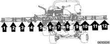
Identifying the Sprayer-Nozzle Hose Positions
Identify the supply hoses by length (Figure 137) for each of the sprayer-nozzle position as follows:
| Sprayer-nozzle positions—left boom section | Sprayer-nozzle positions—center boom section | Sprayer-nozzle positions—right boom section |
|---|---|---|
| Sprayer nozzle 1 (nozzle valve 1)—supply hose 279 cm (110 inches) | Sprayer nozzles 5 and 6 (nozzle valve 5)—supply hose 81 cm (32 inches) with 2 branch hoses | Sprayer nozzle 9 (nozzle valve 7)—supply hose 188 cm (74 inches) |
| Sprayer nozzle 2 (nozzle valve 2)—supply hose 234 cm (92 inches) | Sprayer nozzles 7 and 8 (nozzle valve 6)—supply hose 81 cm (32 inches) with 2 branch hoses | Sprayer nozzle 10 (nozzle valve 8)—supply hose 188 cm (74 inches) |
| Sprayer nozzle 3 (nozzle valve 3)—supply hose 188 cm (74 inches) | Sprayer nozzle 11 (nozzle valve 9)—supply hose 234 cm (92 inches) | |
| Sprayer nozzle 4 (nozzle valve 4)—supply hose 188 cm (74 inches) | Sprayer nozzle 12 (nozzle valve 10)—supply hose 279 cm (110 inches) |
Note: Refer to Figure 138 in Assembling the Hoses to Nozzle Valves 1 through 4, Figure 139 in Assembling the Hoses to Nozzle Valves 5 and 6, and Figure 140 in Assembling the Hoses to Nozzle Valves 7 through 10 for the nozzle-valve positions.
Assembling the Hoses to Nozzle Valves 1 through 4
-
Assemble the straight barbed fitting of a supply hose 279 cm (110 inches) onto the coupler of nozzle valve 1 (Figure 138).
Note: Ensure that the barbed fitting fully seats onto the coupler.
-
Secure the barbed fitting to the coupler with a retainer (Figure 138).
-
Assemble the straight barbed fitting of a supply hose 234 cm (92 inches) onto the coupler of nozzle valve 2 (Figure 138).
Note: Ensure that the barbed fitting fully seats onto the coupler.
-
Secure the barbed fitting to the coupler with a retainer (Figure 138).
-
Assemble the straight barbed fitting of a supply hose 188 cm (74 inches) onto the coupler of nozzle valve 3 (Figure 138).
Note: Ensure that the barbed fitting fully seats onto the coupler.
-
Secure the barbed fitting to the coupler with a retainer (Figure 138).
-
Assemble the straight barbed fitting of a supply hose 188 cm (74 inches) onto the coupler of nozzle valve 4 (Figure 138).
Note: Ensure that the barbed fitting fully seats onto the coupler.
-
Secure the barbed fitting to the coupler with a retainer (Figure 138).
Assembling the Hoses to Nozzle Valves 5 and 6
Note: Supply-hose assembly 81 cm (32 inches) has a T-fitting with 2 branch hoses and 2 single barbed-hose shanks.
-
Assemble the straight barbed fitting of a supply hose 81 cm (32 inches) onto the coupler of nozzle valve 5 (Figure 139).
Note: Ensure that the barbed fitting fully seats onto the coupler.
-
Secure the barbed fitting to the coupler with a retainer (Figure 139).
-
Assemble the straight barbed fitting of a supply hose 81 cm (32 inches) onto the coupler of nozzle valve 6 (Figure 139).
Note: Ensure that the barbed fitting is fully seats onto the coupler.
-
Secure the barbed fitting to the coupler with a retainer (Figure 139).
Assembling the Hoses to Nozzle Valves 7 through 10
-
Assemble the straight barbed fitting of a supply hose 188 cm (74 inches) onto the coupler of nozzle valve 7 (Figure 140).
Note: Ensure that the barbed fitting fully seats onto the coupler.
-
Secure the barbed fitting to the coupler with a retainer (Figure 140).
-
Assemble the straight barbed fitting of a supply hose 188 cm (74 inches) onto the coupler of nozzle valve 8 (Figure 140).
Note: Ensure that the barbed fitting fully seats onto the coupler.
-
Secure the barbed fitting to the coupler with a retainer (Figure 140).
-
Assemble the straight barbed fitting of a supply hose 234 cm (92 inches) onto the coupler of nozzle valve 9 (Figure 140).
Note: Ensure that the barbed fitting fully seats onto the coupler.
-
Secure the barbed fitting to the coupler with a retainer (Figure 140).
-
Assemble the straight barbed fitting of a supply hose 279 cm (110 inches) onto the coupler of nozzle valve 10 (Figure 140).
Note: Ensure that the barbed fitting fully seats onto the coupler.
-
Secure the barbed fitting to the coupler with a retainer (Figure 140).
Routing the Supply Hoses to the Sprayer Nozzles
-
Route the hoses for sprayer nozzles 1, 2, 3, and 4 through the R-clamp at the left outboard end of the center boom section (Figure 141 and Figure 142).
-
Route the hoses for sprayer nozzles 7, 8, 9, and 10 through the R-clamp at the right outboard end of the center boom section (Figure 141 and Figure 142).
-
Route the supply hoses 279 cm (110 inches) and barbed-hose shanks (3/4 inch) along the boom section to sprayer nozzles 1 and 10 as shown in (Figure 141 and Figure 142).
-
Route the supply hoses 234 cm (92 inches) and barbed-hose shanks (3/4 inch) along the boom section to sprayer nozzles 2 and 9 along the boom section as shown in Figure 141 and Figure 142.
-
Route the supply hoses 188 cm (74 inches) and barbed-hose shanks (3/4 inch) along the boom section to sprayer nozzles 3 and 8 as shown in Figure 141 and Figure 142.
Note: Route the hoses through the lower rear grommets in the tube-frame brackets.
-
Route the supply hoses 188 cm (74 inches) and barbed-hose shanks (3/4 inch) along the boom section to sprayer nozzles 4 and 7 as shown in Figure 141 and Figure 142.
Note: Route the hoses through the lower rear grommets in the tube-frame brackets.
-
Bundle the 4 hoses for the sprayer nozzles together with a cable tie as shown in Figure 142.
Installing the Sprayer Nozzles at the Outer Boom Sections
-
Align the transfer tube in the saddle of a sprayer nozzle (Figure 143) with the hole in the side of the single barbed-hose shank (1/2 inch).
-
Close the upper clamp half around the barbed-hose shank and secure the clamp half and spray nozzle body (Figure 143) with the stainless steel screw (#12 x 1-1/4 inches); torque the stainless steel screw to 14 to 18 N∙m (20 to 25 in-lb).
Note: Ensure that the hex-head bolt (5/16 x 3/4 inch) is seated in the recess in the upper clamp half when closing the clamp.
-
Assemble the sprayer nozzles to the outer boom section as follows:
-
At the nozzle positions 1 and 4, assemble the sprayer nozzle to the nozzle mount (A of Figure 144) with the flange locknut (5/16 inch) that you removed in step 2 of Removing the Sprayer Nozzles from the Outer Boom Sections.
-
At the nozzle positions 2 and 3, assemble the sprayer nozzle to the nozzle mount (A and B of Figure 144) with the flange locknut (5/16 inch) that you removed in step 2 of Installing the Sprayer Nozzles at the Outer Boom Sections.
-
-
Torque the flange locknut to 1978 to 2542 N∙cm (175 to 225 in-lb).
-
Repeat steps 1 through 4 for the other sprayer nozzles for the boom section.
-
Repeat steps 1 through 5 to the outer boom section at the other side of the machine.
Connecting the Pressure-Sense Tube for the Dash Gauge
Connecting the Pressure-Sense Tube for the Dash Gauge
Connecting the Pressure Sense-Tube
Installing the Navigation Receiver
Parts needed for this procedure:
| Navigation receiver—GeoLink precision spray system kit (Model 41623) | 1 |
| Receiver mount | 1 |
| U-bolt | 2 |
| RTK-antenna bracket (optional CDMA RTK correction modem kit or GSM RTK correction modem kit) | 1 |
| Flange locknut (3/8 inch) | 4 |
| Hex-head bolt (5 x 16 mm) | 3 |
| Washer (5 mm) | 3 |
| Cellular antenna (optional CDMA RTK correction modem kit or GSM RTK correction modem kit) | 1 |
| Coaxial cable (optional CDMA RTK correction modem kit or GSM RTK correction modem kit) | 1 |
| Serial label (part of the X25 or the X30 GeoLink Precision Spray System Kits) | 1 |
Assembling the Navigation Receiver to the Machine
-
Align the slot that is in the center of the receiver mount with the weld seam at the centerline of the ROPS tube (Figure 148).
Note: Ensure that the larger flange with 2 holes is rearward of the ROPS tube and the smaller flange with 1 hole is forward.
-
Assemble the receiver mount to the ROPS tube as follows:
-
If your machine is configured with global navigation satellite system (GNSS) with wide area augmentation system (WAAS), assemble the receiver mount to the ROPS tube (Figure 149) with the 2 U-bolts and 4 flange locknuts (3/8 inch).
-
If your machine has GNSS and the CDMA or GSM RTK correction modem kit, assemble the receiver mount and RTK-antenna bracket to the ROPS tube (Figure 150) with the 2 U-bolts and 4 flange locknuts (3/8 inch).
-
-
Torque the nuts to 37 to 45 N∙m (27 to 33 ft-lb).
-
Align the 3 threaded in the base of the navigation receiver to the 3 holes in the receiver mount (Figure 151).
-
Assemble the receiver to the mount (Figure 151) with the 3 hex-head bolt (5 x 16 mm) and 3 washers (5 mm).
-
Torque the 3 bolts to 576 to 712 N∙cm (51 to 63 in-lb).
-
Apply the serial label to the receiver mount (Figure 152).
Note: The label is part of the X25 or the X30 GeoLink Precision Spray System Kits.
Installing the RTK Antenna to the Navigation Receiver
Note: Install the RTK antenna when your machine is equipped with a CDMA RTK or GSM RTK correction modem.
-
Align the coaxial coupler through the opening in RTK-antenna bracket with the bulkhead threads of the coupler down (Figure 153).
Note: Rotate the coaxial coupler as needed to align the flat of the bulkhead threads with the flat at the opening in RTK-antenna bracket.
-
Assemble the coaxial coupler to the antenna bracket with the lock washer and jam nut, and tighten the jam nut by hand (Figure 153).
-
Assemble the RTK antenna onto the upper fitting of the coaxial coupler, and tighten the knurl nut of the antenna by hand (Figure 154).
-
Loosely assemble the antenna cable to the lower fitting of the coaxial coupler (Figure 154).
-
Route the cable around the back of the navigation receiver to the coaxial connector of the CDMA or GSM cellular modem (Figure 154).
-
Assemble the antenna cable to coaxial connector of the CDMA or GSM cellular modem (Figure 154).
-
Tighten the knurl nuts of the antenna cable by hand.
Installing the Sprayer Monitor
Parts needed for this procedure:
| Sprayer Monitor—GeoLink precision spray system kit 41623 | 1 |
| Display hood | 1 |
| Ball mount—GeoLink precision spray system kit 41623 | 1 |
| Monitor arm—GeoLink precision spray system kit 41623 | 1 |
| Reinforcement plate | 1 |
| Flange-head bolt (1/4 x 1-1/2 inches) | 4 |
| Flange locknut (1/4 inch) | 4 |
Assembling the Display Hood to the Sprayer Monitor
-
At the back of the sprayer monitor and with the 2 connectors (26 pin) aligned down, remove the top locknut (5 mm) from the stud for the ball-pivot fitting (Figure 155).
-
Apply a coat of thread-locking compound (wicking—medium-high strength) to the threads for the nut portion of the threaded standoff (Figure 156).
-
Thread the standoff into the stud for the ball-pivot fitting (Figure 155) and torque the standoff to 250 N·cm (22 in-lb).
-
Apply a coat of thread-locking compound (wicking—medium-high strength) to the threads for the stud portion of the threaded standoff (Figure 156).
-
Align the hole in the display hood with the stud portion of the threaded standoff (Figure 155).
-
Assemble the hood to the monitor with the locknut (5 mm) that you removed in step 1.
-
Torque the nut to 250 N·cm (22 in-lb).
Drilling the Dash Panel
-
At the dash of the machine, locate the dash-panel screw to the right of the hole grommet in the dash (Figure 157).
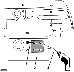
-
Measure to the right of the center of the screw 33.3 mm (1-5/16 inches) and with a pencil, mark the location with a vertical line (Figure 157).
-
Measure from the top edge of the dash panel down 21 mm (13/16 inch), and mark the location with a horizontal line.
-
Center-punch the dash panel at the intersection of the marks.
-
Drill the dash panel at the center-punch mark with an 8 mm (5/16 inch) drill bit (Figure 157).
-
Temporarily align the flat side of the stiffener plate to the dash panel with a flange-head bolt (1/4 x 1-1/2 inches).
-
Align the stiffener plate horizontally to the top of the dash panel and using the stiffener as a template, drill the remaining 3 holes in the dash (Figure 157).
-
Remove the stiffener plate from the face of the dash panel.
Mounting the Sprayer Monitor to the Dash of the Machine
-
Assemble the ball-pivot mount to the dash with the 4 bolts (1/4 x 1-1/2 inches), stiffener plate, and flange locknut (1/4 inch) as shown in Figure 158.
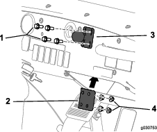
-
Torque the bolts and nuts to 1017 to 1243 N·cm (90 to 110 in-lb).
-
Loosen the knob of the monitor arm until you can slip both the ball pivot for the fitting at the back of the sprayer monitor and the ball pivot for the mount at the dash panel into the socket monitor arm (Figure 159).
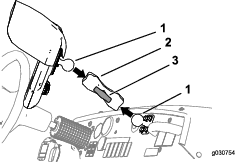
-
From the driver’s seat (left seat), adjust to position of the sprayer monitor so that you can easily view the display screen (Figure 159).
-
Tighten the knob for the monitor arm by hand (Figure 159).
Installing the Sprayer Controller and Connecting the Rear Wire Harness
Parts needed for this procedure:
| Sprayer controller—GeoLink precision spray system kit 41623 | 1 |
| Bolt (4 x 10 mm) | 4 |
| Flange locknut (4 mm) | 4 |
Installing the Sprayer Controller
-
Align the sprayer controller the forward side of the valve mount with the 40-pin connector outward (Figure 160).
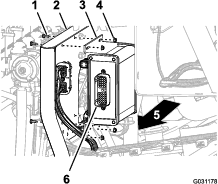
-
Assemble the sprayer controller to the valve mount (Figure 160) with the 4 bolts (4 x 10 mm) and 4 flange locknuts (4 mm).
-
Torque the bolts and nuts to 234 to 286 N·cm (21 to 25 to in-lb).
Connecting the Rear Wire Harness to the Controller
-
Align the 40 socket connector labeled ASC 10 of the 203 cm (80 inches) wire harness branch with the 40-pin connector sprayer controller (Figure 161).
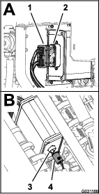
-
Plug the 40-socket connector into the 40-pin connector until both connectors are firmly seated.
-
Align the 4 socket connector labeled To ASC 10 of the 203 cm (80 inch) wire-harness branch with the 4-pin connector sprayer controller (Figure 161).
-
Plug the 4-socket connector into the 4-pin connector until both connectors are firmly seated.
Installing the Wire Harnesses for the Navigation Components
Parts needed for this procedure:
| Data Harness (navigation system)—GeoLink precision spray system kit (Model 41623) | 1 |
| Electrical Harness (navigation system)—GeoLink precision spray system kit (Model 41623) | 1 |
| Cable tie | 5 |
Connecting the Navigation Data and Electrical Harnesses
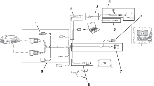
-
If not installed, insert the terminating resistor into the electrical connector at the 390 cm (153-1/2 inch) data-harness branch for the navigation receiver (Figure 162).
-
If not installed, insert the terminating resistor into the electrical connector at the 220 cm (86-5/8 inch) data-harness branch for the sprayer monitor (Figure 162).
-
Connect the 3-socket connector (electrical-power interface) of the navigation-electrical harness to the 3-pin connector (electrical-power interface) of the data harness (Figure 162 and Figure 163).
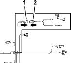
Routing and Connecting the Data Cable to the Navigation Receiver
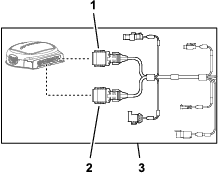
-
Route the 390 cm (153-1/2 inches) branch of the data harness into the right side of the engine compartment (adjacent to the air filter for the engine) and rearward under the bottom right area of the rear engine shroud (Figure 165).
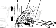
-
Route the 390 cm (153-1/2 inches) branch of the data harness along the right ROPS tube with the 12-socket connector (gray) and 12-socket connector (black) up toward the navigation receiver (Figure 166).
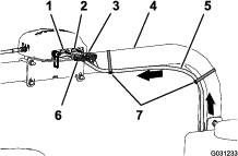
-
Align the 2 keys at the long face of the gray and black 12-socket connector of the data harness with the 2 key slots in the bottom, horizontal wall of the left (gray) 12-pin connector of the navigation receiver (Figure 167).
Note: Use caution when connecting wire harness to the navigation receiver; the alignment keys of the harness connectors are unique to the keyways of the pin connectors of the navigation receiver.
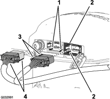
-
Connect the gray and black 12-socket connector of the data harness into the left (gray) 12-pin connector of the navigation receiver until the connector locks snap together securely (Figure 167).
-
Align the 2 keys at the short side of the black 12-socket connector of the data harness with the 2 key slots in the left, vertical wall of the right (black) 12-pin connector of the navigation receiver (Figure 167).
Note: Use caution when connecting wire harness to the navigation receiver; the alignment keys of the harness connectors are unique to the keyways of the pin connectors of the navigation receiver.
-
Connect the black only 12-socket connector of the data harness into the left (black) 12-pin connector of the navigation receiver until the connector locks snap together securely (Figure 167).
-
Secure the 390 cm (153-1/2 inches) branch of the data harness to the right ROPS tube with 2 cable ties as shown in Figure 166.
Note: Ensure that the cable is slack between the 12-socket connectors and the cable tie.
Connecting the Navigation Electrical and Data Harnesses to the Rear Wire Harness of the Machine
-
Route the 100 cm (39-3/8 inches) branch of the electrical harness (Figure 168) with the 1-pin connector, down to the area where the front and rear wire harness for the machine connect; refer to Figure 86 in Connecting the Front and Rear Wire Harnesses.
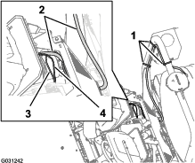
-
Route the 100 cm (39-3/8 inches) branch of the data harness (Figure 168) with the 4-pin connector for the CAN 2/sprayer controller, down to the area where the front and rear wire harness for the machine connect; refer to Figure 86 in Connecting the Front and Rear Wire Harnesses.
-
Connect the 4-pin connector of the data harness for the CAN 2/sprayer controller into the 4-socket connector of the rear harness for the CAN 2/sprayer-controller circuit (Figure 169).
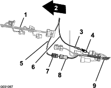
-
Connect the 1-pin connector of the electrical-harness to the 1 socket connector of the rear wire harness (Figure 169).
Routing the Navigation Electrical Harness to the Battery
-
Route the 220 cm (86-5/8 inches) branch of the electrical harness for the navigation system across the seat-box angle and down along the left support for the engine shroud (Figure 170).
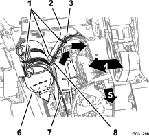
-
Secure the harness to the engine-shroud support with cable ties (Figure 170).
-
Route the 220 cm (86-5/8 inches) branch of the electrical harness for the navigation system down along the left support for the engine shroud and under the left frame tube (Figure 171).
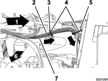
-
Secure the harness to the hole in the seat-box angle and the engine-shroud support with 3 cable ties (Figure 171 and Figure 172).

-
Route the 10 A fuse and the positive and negative ring terminals of the 220 cm (86-5/8 inches) branch of the electrical harness for the navigation system to the top of the battery (Figure 172).
Note: You will complete the installation of the ring terminals in Assembling the Rear Harness and Navigation Electrical Harness to the Battery Cables.
Routing and Connecting the Data Cable to the Sprayer Monitor
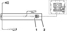
-
At the right side of the engine compartment, route the 220 cm (86-5/8 inches) branch of the data harness forward of the air filter for the engine and down toward the lower right corer of the radiator (Figure 174).
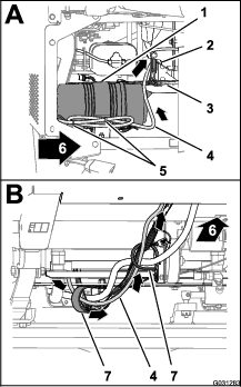
-
Route the route the 220 cm (86-5/8 inches) branch of the data harness forward and through the 2 R-clamps at the bottom of the machine (Figure 174).
-
Route the route the 220 cm (86-5/8 inches) branch of the data harness forward and up through grommet that surrounds the hole in the floor panel (Figure 175).
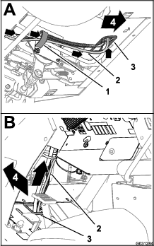
-
Route the route the 220 cm (86-5/8 inches) branch of the data harness up and along the front wire harness of the machine (Figure 175).
-
Route the route the 220 cm (86-5/8 inches) branch of the data harness up through grommet that surrounds the hole in the dash panel (Figure 176).
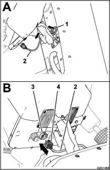
-
Align the 26-socket connector of the data harness with the 26-pin connector of the sprayer display and press the socket connector into the pin connector until the latch of the connector snaps securely (Figure 176).
Assembling the Rear Harness and Navigation Electrical Harness to the Battery Cables
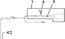
-
Route the positive terminal (red wire), negative terminal (black wire), and 50 A fuse block of the rear wire harness up between the battery box and the chassis of the machine (Figure 178).
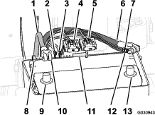
-
Route the positive terminal (red wire), negative terminal (black wire), and 10 A fuse block of the navigation-electrical harness up between the battery box and the chassis of the machine.
-
Remove the T-bolts and hex nuts from the terminals of the positive and negative battery cables (Figure 178).
-
Assemble a T-bolt through the positive terminal (red wire) of the rear wire harness, the positive terminal of the navigation electrical harness, and terminal of the positive battery cable (Figure 178).
-
Loosely secure the terminals and the T-bolt with a hex nut (Figure 178).
Note: Do not install the battery cable to the battery at this time.
-
Assemble a T-bolt through the negative terminal (black wire) of the rear wire harness, the negative terminal of the navigation electrical harness, and terminal of the negative battery cable (Figure 178).
-
Loosely secure the terminals and the T-bolt with a hex nut (Figure 178).
Note: Do not install the battery cables to the battery at this time.
Installing the Optional Undercarriage Shroud Kit
-
Align the undercarriage shroud to the bottom chassis of the machine (Figure 179).
-
Slip the support straps of the undercarriage shroud over the bolts and carriage bolt at the engine-mount brackets of the machine (Figure 179).
-
Assemble the undercarriage shroud to the engine-mount brackets and bolts (Figure 179) with the 4 flange locknuts (5/16 inch) that you removed in step 2 of Removing the Optional Undercarriage Shroud Kit.
-
Align the holes in the rear part of the undercarriage shroud with the holes in the chassis (Figure 180).
-
Assemble the rear part of the undercarriage shroud to the chassis with the 7 flange-head bolts (5/16 x 7/8 inch) and 7 washers (5/16 inch) that you removed in step 1 of Removing the Optional Undercarriage Shroud Kit (Figure 180).
-
Torque the nuts and bolts to 1129 to 1582 N∙cm (100 to 140 in-lb).
Connecting the Optional Hand Spray Wand Kit, Electric Hose Reel Kit, or Pivoting Hose Reel Kit
Parts needed for this procedure:
| 90° elbow with side port (Toro Part No. 131-3726) | 1 |
| Flange clamp and gasket (Toro Part No. 127-9829) | 1 |
| Shutoff valve (Toro Part No. 130-7321) | 1 |
Installing the Control Box to the Manifold Mount
-
Align the hose in the mounting plate for the control box with the holes or slots in the manifold mount for the sprayer valves (Figure 181).
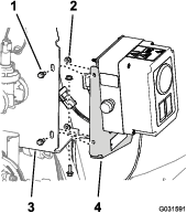
-
Assemble the control box to the manifold mount (Figure 181) with the 3 flange-head bolts (1/4 x 5/8 inch) and 3 serrated-flange nuts (1/4 inch) that you removed in step 1 of Removing the Control Box from the Manifold Mount.
-
Torque the nuts and bolts to 1017 to 1243 N·cm (90 to 110 in-lb).
Installing the Pivoting Hose Reel to the Manifold Mount
Lifting equipment capacity: 57 kg (125 lb)
-
Lift the pivoting hose reel with lifting equipment with the specified capacity.
-
Align the holes in the support channel for the pivoting-hose reel with the holes in the manifold mount for the sprayer valves (Figure 182).
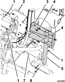
-
Align the holes in the lower tube frame for the pivoting-hose reel with the holes in the mounting bracket at the right frame channel of the machine (Figure 182).
-
Assemble the support channel to the manifold mount (Figure 182) with the 4 flange-head bolts (3/8 x 1 inch) and flange locknuts (3/8 inch) that you removed in step 3 of Removing the Pivoting-Hose Reel from the Manifold Mount.
-
Assemble the lower tube frame to the mounting bracket (Figure 182) with the 2 flange-head bolts (3/8 x 2-1/4 inches) and 2 flange locknuts (3/8 inch) that you removed in step 2 of Removing the Pivoting-Hose Reel from the Manifold Mount.
-
Torque the bolts and nuts to 37 to 45 N·m (27 to 33 ft-lb).
Assembling the Hose and Fittings
-
Remove the tube coupler from the cap at the flange at the right end of nozzle valve 10 (Figure 183).
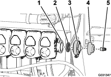
-
Remove the flange clamp, gasket, and end cap from nozzle valve 10 (Figure 183).
Note: Retain the tube connector, flange clamp, and gasket for installation later in this procedure. You no longer need the end cap that you removed from the machine.
-
Apply PTFE thread-sealing tape to the threads of the T-fitting (Figure 184) that you removed in step 3 of Disconnecting the Hoses and Tubing.
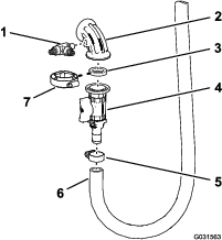
-
Assemble the T-fitting into the 90° elbow with side port as shown in either Figure 184, and tighten the fitting by hand.
-
Loosely assemble the 90° elbow with side port, gasket, and shutoff valve with the flange clamp (Figure 184).
-
Assemble the barbed fitting of the shutoff valve into with the inlet hose and hose clamp (Figure 184) that you removed in step 4 of Disconnecting the Hoses and Tubing.
Installing the Hose and Sense Tubes
-
Align the gasket and 90° elbow for the hose reel to the flange from nozzle valve 10 (Figure 185).
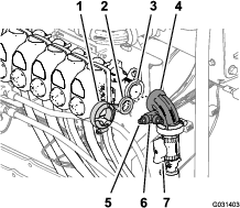
-
Secure the elbow and gasket to the valve with a flange clamp and tighten the clamp by hand (Figure 185).
-
Apply a coat of PTFE thread sealant to the threads of the tube coupler and install the tube couple into the T-fitting as shown in Figure 185.
-
Insert the end of the pressure-sense tube for the dash-pressure gauge into the tube coupler until the tube fully seats in the coupler (Figure 186).
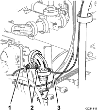
-
Insert the end of the pressure-sense tube for the pressure gauge of the hose reel into the tube coupler until the tube fully seats in the coupler (Figure 186).
Connecting the Optional Hand Sprayer Kit or Electric Hose Reel Kit Harness
Connecting the Wire Harness for the Optional Pivoting Hose Reel Kit
-
At the back of the machine, locate the wire harness for the pivoting hose-reel kit at the back of the sprayer tank (Figure 189).
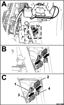
-
Remove the plug from the 2-pin connector of the rear, main harness for the hose-reel power (Figure 189).
-
Connect the 2-socket connector of the harness for the electric-hose reel into the 2 pin connector of the rear, main harness (Figure 189).
-
Remove the cap from the 3-socket connector of the rear, main harness for the spray-harness interconnect (Figure 189).
-
Connect the 3-pin connector of the harness for the electric-hose reel into the 3 pin socket of the rear, main harness (Figure 189).
Connecting the Optional Foam Marker Kit
Parts needed for this procedure:
| Wire harness—optional Foam Marker Finishing Kit 130-8292 | 1 |
| Cable tie—optional Foam Marker Finishing Kit 130-8292 | 5 |
| Relay—optional Foam Marker Finishing Kit 130-8292 | 1 |
| Flange-head bolt (#10-24 x 1/2 inch)—Foam Marker Finishing Kit 130-8292 | 1 |
| Locknut (#10-24—optional Foam Marker Finishing Kit 130-8292) | 1 |
| Auxiliary fuse block—Toro Part No. 92–2641 | 1 |
| Fuse (15 A—optional Foam Marker Finishing Kit 130-8292) | 1 |
| Flange-head bolts (6 x 12 mm)—optional Foam Marker Finishing Kit 130-8292 | 4 |
| Mounting bracket (foam-control switch)—optional Foam Marker Finishing Kit 130-8292 | 1 |
| 3-position paddle switch (foam-control switch)—optional Foam Marker Finishing Kit 130-8292 | 1 |
| 2-position rocker switch (compressor on/off switch)—optional Foam Marker Finishing Kit 130-8292 | 1 |
Routing the Compressor Branch of the Wire Harness
-
Locate the 236 cm (93 inches) compressor branch of the wire harness with a 4-socket connector and route the wiring branch rearward along the sprayer tank as shown in Figure 190 and Figure 191.
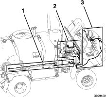
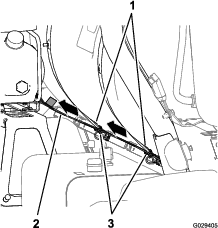
-
Route the 4-socket connector of the harness to the 4-pin connector of the compressor and connect the 2 connectors.
Note: The compressor is located above the foam-marker tank.
Routing the Engine-Compartment Branch of the Wire Harness
-
Route the wire harness for the finishing kit forward between the ROPS bar and the lower corner of the sprayer tank, along the wire harness of the machine, and below the air cleaner for the engine (Figure 192 and Figure 193).
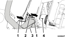
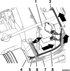
-
Route the 197 cm (77-1/2 inches) engine compartment branch of the wire harness (with the ring terminal, socket terminal, and 5-socket connector) up along the right side of the radiator, across the top of the radiator, under the base of the center console (Figure 193).
-
Route the 197 cm (77-1/2 inches) engine compartment branch of the wire harness down along the left side of the radiator and across the bottom of the electrical panel (Figure 194).
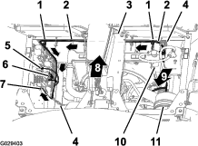
-
Secure the wire harness for the finishing kit to the wire harness for the machine with 2 cable ties as shown in Figure 194.
Routing the Dash Panel Branch of the Wire Harness
-
Route the 240 cm (94-1/2 inches) dash panel branch of the wire harness along the wire harness and steering hoses of the machine (below the radiator), through the R-clamp at the bottom of the radiator support, through the R-clamp at the ground-speed-control coil (Figure 195 and Figure 196).
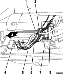
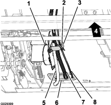
-
Route the 240 cm (94-1/2 inches) dash panel branch of the wire harness to the R-clamp at the ground-speed-control coil (Figure 195 and Figure 196).
-
Route the 240 cm (94-1/2 inches) dash panel branch of the wire harness through the grommet at the opening in the forward bulkhead and inboard of the cable and hose hook (Figure 197).
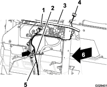
-
Route the 8-socket connector at the end of the 240 cm (94-1/2 inches) dash panel branch across the dash panel and to the left of the steering column (Figure 198).
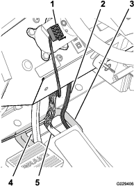
-
Adjacent to the cable and hose hook, secure the 240 cm (94-1/2 inches) dash panel branch to the wire harness for the machine with a cable tie (Figure 199).
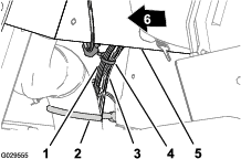
Connecting the Compressor Wire Harness
-
At the end of the 236 cm (93 inches) branch of the wire harness, align the 4-socket connector of the wire harness for the finishing kit with the 4-pin connector of the wire harness from the compressor (Figure 200).
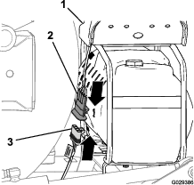
-
Insert the 4-pin connector into the 4-socket connector (Figure 200).
Note: Press the connectors together until the latch snaps securely.
Installing the Relay
-
At the 197 cm (77-1/2 inches) engine-compartment branch of the wire harness, align the relay with the 5-socket connect of the wire harness for the finishing kit (Figure 201).
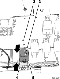
-
Insert the pins of the relay into the sockets of the connector (Figure 201).
Note: Press the relay and connector together until the latch snaps securely.
-
Align the hole in the mounting tab of the relay with the hole in the wiring panel (Figure 201).
-
Secure the relay to the panel (Figure 201) with the flange-head bolt (#10 x 1/2 inch) and locknut (#10).
Connecting the Ground-Wire Terminal
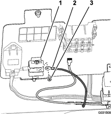
Connecting the Load Wire Connectors—Machine Fuse Block
Note: If you do not have a bladed-attachment connector at the fuse block for the machine available, you will need to install an auxiliary-fuse block.
-
For a machine with the bladed-attachment connector at the fuse block for the machine, connect the blade connector of the wire harness for the finishing kit to the socket connector of the fuse block for the machine (Figure 203).
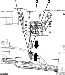
-
Press the connectors together until the latch snaps securely.
Connecting the Load Wire Connectors
-
Connect the blade connector of the wire harness for the finishing kit to the socket connector of the auxiliary-fuse block (Figure 204).
Note: Press the connectors together until the latch snaps securely.
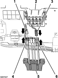
-
Connect the 2-pin connector for the auxiliary-feed wires of the fuse block for the machine to the 2-socket connector for the feed wires of the auxiliary-fuse block (Figure 204).
Note: Press the connectors together until the latch snaps securely.
-
Align the slots in the auxiliary-fuse block with the mounting flanges of the fuse block of the machine (Figure 205).
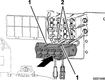
-
Assemble the fuse blocks together until the latch snaps securely.
Installing the Fuse
-
For a machine with the bladed-attachment connector at the fuse block for the machine, install the 15 A fuse into the fuse block (Figure 206).
Note: Ensure that the fuse is fully seated into the socket of the fuse block.
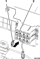
-
For a machine with a bladed attachment connector at the optional auxiliary-fuse block, perform the following:
-
Locate the fuse socket that is aligned with the wire of the blade connector that you used in step 1 of Connecting the Load Wire Connectors.
-
Install the 15 A fuse into the socket that you located in the auxiliary-fuse block (Figure 207).
Note: Ensure that the fuse fully seats into the socket of the fuse block.
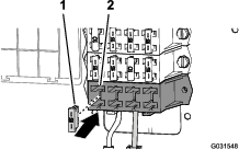
Installing the Foam-Control Switch
-
Align the slots in the mounting bracket for the foam-control switch with the 4 threaded inserts in the steering column (Figure 208).
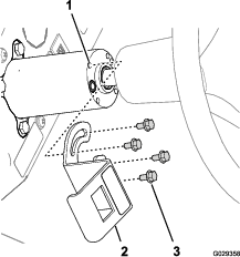
-
Assemble the bracket to the column with the 4 flange-head bolts (6 x 12 mm) and torque the bolts to 972 to 1198 N·cm (86 to 106 in-lb).
-
Align the 8-socket connector through the opening in the bracket and connect the connector to the pins (Figure 208) at the back of the 3-position paddle switch (foam-control switch).
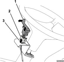
-
Assemble the switch into the bracket and press in the switch until it snaps securely into the opening (Figure 209).
Note: Ensure that the paddle for the 3-position paddle switch (foam-control switch) is aligned outward.
Installing the Compressor Switch
-
Remove the fifth plug to the right in the dash panel of the machine (Figure 210).
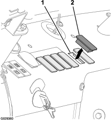
-
Align the 8-socket connector through the opening in the dash panel and connect the connector (Figure 211) to the pins at the back of the 2-position rocker switch (compressor on/off switch).
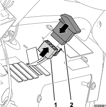
-
Assemble the switch into the dash panel and press in the switch until the it snaps securely into the opening (Figure 210 and Figure 211).
Connecting the Tubing for the Foam-Marker Nozzles
-
Route the tubes for the foam nozzles at the left and right boom section inboard and through the R-clamp near the pivot point for the boom section (Figure 212).
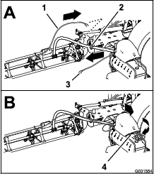
-
Route the tubes forward along the inboard side of the compressor for the tank (Figure 212).
-
Connect the tubing with the cable tie that you installed in step 1 of Removing the Liquid and Air Tubes from the Machine by aligning the blue tube for the right boom section onto the compression fitting for the right boom section water circuit (Figure 213).
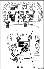
-
Assemble the compression nut for the tube onto the fitting and tighten the nut by hand (Figure 213).
-
Aligning the clear tube for the right boom section onto the compression fitting for the right boom section air circuit (Figure 213).
-
Assemble the compression nut for the tube onto the fitting and tighten the nut by hand (Figure 213).
-
Connect the unmarked (no cable tie) tubing by aligning the blue tube for the left boom section onto the compression fitting for the left boom section water circuit (Figure 214).
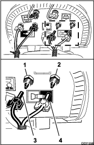
-
Assemble the compression nut for the tube onto the fitting and tighten the nut by hand (Figure 214).
-
Aligning the clear tube for the left boom section onto the compression fitting for the left boom section air circuit (Figure 214).
-
Assemble the compression nut for the tube onto the fitting and tighten the nut by hand (Figure 214).
Connecting the Optional Chemical Pre-Mix Kit
Parts needed for this procedure:
| Fluid-shutoff valve—Toro Part No. 130-7324 | 1 |
| Retainer—Toro Part No. 131-0235 | 2 |
| Mount (fluid-shutoff valve)—Toro Part No. 131-3725-03 | 1 |
| Flange locknut (1/4 inch, stainless steel)—Toro Part No. 119-6897 | 2 |
| Pressure relief-hose assembly 25 x 273 mm (1 x 10⁻³/4 inches)—Toro Part No. 131-9647 | 1 |
| Supply-hose assembly 25 x 470 mm (1 x 18-1/2 inches)—Toro Part No. 131-9648 | 1 |
| Agitation bypass-hose assembly 25 x 305 mm (1 x 12 inches)—Toro Part No. 131-9649 | 1 |
| 90° barb fitting 25 mm (1 inch)—Toro Part No. 131-3727 | 1 |
| Drain hose 25 x 1587 mm (1 x 62-1/2 inches)—Toro Part No. 117-7957 | 1 |
Repositioning the Pressure-Relief Valve
-
Remove the retainer that secures the straight barbed fitting of the supply hose to the T-fitting at the sprayer pump and remove the straight fitting from the T-fitting (Figure 215).
Note: Retain the retainer for installation in step 2 of Installing the Supply-Hose Assembly.
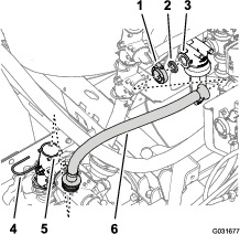
-
Remove the flange clamp that secures the supply hose and gasket to the flange of the filter head and remove the hose from the machine (Figure 215).
-
Remove the retainer that secures the pressure-relief valve to the T-fitting at the sprayer pump as remove the relief valve (Figure 216).
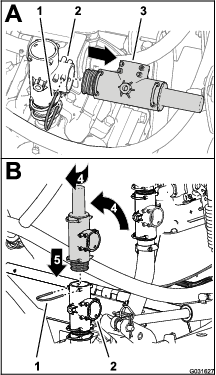
-
Rotate the pressure relief valve up as shown in Figure 216.
Note: Align outlet of the pressure-relief valve rearward.
-
Insert the pressure-relief valve into the top of the T-fitting until the valve is fully seated (Figure 216).
-
Secure the pressure-relief valve to the T-fitting with the retainer that you removed in step 3.
Replacing the Bypass Hose for the Agitation Valve
-
Remove the retainer that secures the 90° barbed fitting for the bypass hose to the upper T-fitting and remove the 90° fitting from the T-fitting (Figure 217).
Note: Retain the retainer for installation in a later step 5.
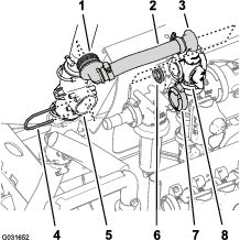
-
Remove the flange clamp that secures the straight flange fitting and gasket to the flange of the agitation valve, and remove the bypass hose from the machine (Figure 217).
Note: Retain the flange clamp and gasket for installation step 7; you no longer need the old 90° fitting, bypass hose, and straight flange fitting that you removed from the machine.
-
Rotate the upper T-fitting approximately 45° clockwise (Figure 218).
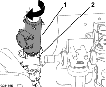
-
Align the 90° barbed fitting of the new agitation bypass-hose assembly (Toro Part No. 131-9649) with the open port in the upper T-fitting and insert the 90° fitting until it is seated in the T-fitting (Figure 219).
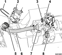
-
Secure the 90° barbed fitting to the T-fitting with the retainer (Figure 219) that you removed in step 1.
-
Align the straight flange fitting of the new agitation bypass-hose assembly (Toro Part No. 131-9649) and the gasket with the flange of the bypass valve (Figure 219).
-
Secure the straight flange fitting and gasket to the bypass valve with the flange clamp that you removed in step 2.
Preparing to Install the Fluid-Shutoff Valve for the Eductor
-
Align the 90° barb fitting (Toro Part No. 131-3727) to the fluid-shutoff valve (Toro Part No. 130-7324) as shown in Figure 220 and insert the barbed fitting into the valve until the fitting fully seats.
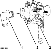
-
Secure the 90° barb fitting to the fluid-shutoff valve with a retainer (Toro Part No. 131-0235).
-
Remove the flange clamp that secures the straight-barbed fitting and gasket to the flange of the filter head and remove the fitting (Figure 221).
Note: Retain the flange clamp and gasket for installation of the fluid-shutoff valve in step 5 of Installing the Fluid-Shutoff Valve for the Eductor; you no longer need the straight-barbed fitting that you removed from the machine.
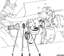
-
Remove the 2 flange locknuts (5/16 inch) that secure the filter head to the manifold mount (Figure 222).
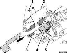
-
Align the holes in the long flange of shutoff-valve mount (Toro Part No. 131-3725-03) to the 2 bolt (5/16 x 4 inches) at the front side of the manifold mount (Figure 222).
-
Attach the shutoff-valve mount to the manifold mount and bolts with 2 flange locknut that you removed in step 4 (Figure 222).
-
Torque the bolts and nuts 1978 to 2542 N·cm (175 to 225 in-lb).
Installing the Fluid-Shutoff Valve for the Eductor
-
Align the gasket to the flange of the filter head (Figure 223).
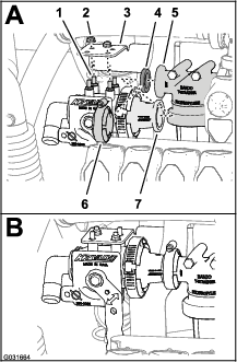
-
Align the studs of the fluid-shutoff valve (Toro Part No. 130-7324) with the 4 holes in the shutoff-valve mount (Toro Part No. 131-3725-03) and the flange adapter of the fluid-shutoff valve with the flange of the filter head and gasket (Figure 223).
-
Assemble the fluid-shutoff valve to the shutoff-valve mount with 2 flange locknut (1/4 inch)—Toro Part No. 119-6897 at 2 diagonally aligned studs of the fluid-shutoff valve as shown in Figure 223.
-
Torque the flange locknut (1/4 inch) to 1070 to 1243 N·cm (90 to 110 in-lb).
-
Secure the flange adapter of the fluid-shutoff valve to the flange of the filter head with the clamp (Figure 223) that you removed in 3 of Preparing to Install the Fluid-Shutoff Valve for the Eductor.
Installing the Pressure Relief-Hose Assembly
-
Align the 90° fitting of the pressure relief-hose assembly (Toro Part No. 131-9647) with the open port of the pressure-relief valve and insert the 90° fitting until it is seated in the T-fitting (Figure 224).
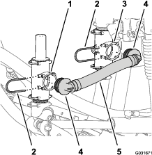
-
Secure the 90° fitting to the pressure-relief valve with the retainer (Figure 224) that you removed in step 1 of Installing the Pivoting Hose Reel to the Manifold Mount.
-
Align the other 90° fitting of the pressure relief-hose assembly (Toro Part No. 131-9647) with the open port of the lower T-fitting and insert the 90° fitting until it is seated in the T-fitting (Figure 224).
-
Secure the 90° fitting to the upper T-fitting with the retainer (Figure 224) that you removed in step 2 of Installing the Pivoting Hose Reel to the Manifold Mount.
Installing the Supply-Hose Assembly
-
Align the other 90° fitting of the supply-hose assembly (Toro Part No. 131-9648) with the open port of the T-fitting at the sprayer pump and insert the 90° fitting until it is seated in the T-fitting (Figure 225).
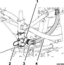
-
Secure the 90° fitting to the T-fitting at the sprayer pump with the retainer (Figure 225) that you removed in step 1 of Repositioning the Pressure-Relief Valve.
-
Align the other 90° fitting of the pressure-hose assembly (Toro Part No. 131-9648) with the open port of the T-fitting at the sprayer pump and insert the 90° fitting until it seats in the T-fitting (Figure 226).
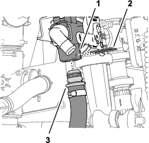
-
Align the straight-barbed fitting of the pressure-hose assembly (Toro Part No. 131-9648) with the bottom port of the fluid-shutoff valve and insert the straight fitting until it seats in the valve (Figure 226).
-
Secure the straight-barbed fitting to the fluid-shutoff valve (Figure 224) with a retainer (Toro Part No. 131-0235).
Connecting the Eductor-Supply Hose
-
Align the free end of the eductor-supply hose to the 90° barbed fitting of the fluid-shutoff valve and install the hose over the fitting (Figure 227).
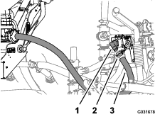
-
Secure the hose to the fitting with the hose clamp that you removed in step 7 of Installing the Pivoting Hose Reel to the Manifold Mount.
Connecting the Optional EU Compliance Kit
Drilling the Manifold Mount
-
At the top-left edge of the manifold mount, measure 381 mm (15 inches) to the right, and mark the manifold mount with a pencil (Figure 228).
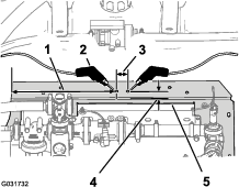
-
At the rear edge of the manifold mount, measure 19 mm (3/4 inch) forward, and mark the manifold mount with a pencil (Figure 228).
-
At the intersection of the 2 marks that you made in steps 1 and 2, center punch the horizontal surface e of the manifold mount.
-
At the center-punch mark, measure to the right 32 mm (1-1/4 inches), and mark the manifold mount with a pencil (Figure 228).
-
At the rear edge of the manifold mount, measure 19 mm (3/4 inch) forward, and mark the manifold mount with a pencil (Figure 228).
-
At the intersection of the 2 marks that you made in steps 4 and 5, center punch the horizontal surface e of the manifold mount.
-
Drill a hole in the manifold mount at each of the center-punch marks with an 8 mm (5/16 inch) drill bit (Figure 228).
Installing the Ball Valve and Mounting Bracket
-
Align the holes in the mounting bracket for the ball valve that you removed in step 4 of Disconnecting the Optional EU Compliance Kit with the holes manifold mount that you drilled in Drilling the Manifold Mount as shown in Figure 229.
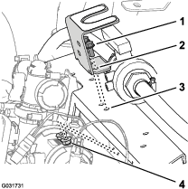
-
Assemble the mounting bracket to the manifold mount (Figure 229) with the 2 flange-head bolts (5/16 x 3/4 inch) and flange locknuts (5/16 inch) that you removed in step 4 of Disconnecting the Optional EU Compliance Kit.
-
Torque the bolts and nuts to 1978 to 2542 N·m (175 to 225 in-lb).
-
Align the threaded boss of the ball valve with the 2 holes in the mounting bracket (Figure 230).
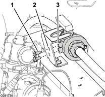
-
Assemble the valve to the mounting bracket (Figure 230) with the 2 flange-head bolts (5/16 x 5/8 inch) that you removed in step 3 of Disconnecting the Optional EU Compliance Kit, and tighten the bolts by hand.
Assembling the Optional Covered Boom Kit
Parts needed for this procedure:
| Cover extension assembly (12-nozzle—Toro Part No. 120-0621) | 1 |
| Pop rivet (Toro Part No. 114439) | 22 |
| Support bracket (center section cover—Toro Part No. 131–3703–03) | 4 |
| Clip nut (Toro Part No. 94-2413) | 4 |
| Flange-head bolt (3/8 x 1-1/4 inches—Toro Part No. 110-5050) | 16 |
| Flange locknut (3/8 inch—Toro Part No. 104-8301) | 16 |
| Cover strap (Toro Part No. 120–0629) | 2 |
| Flange-head bolt (5/16 x 1-1/4 inches—Toro Part No. 323-36) | 4 |
Installing the Cover Extension on to Center Section Cover (11 Nozzle)
-
Using a drill with a 5 mm (3/16 inch) drill bit, drill the 11 pop rivets (Figure 231) that secure the reinforcement plate (single row) and rubber cover to the end of the 11-nozzle section cover for the center boom section that you removed in step 2 of Removing the Center Section Cover (11 Nozzle) of the Optional Covered Boom Kit.
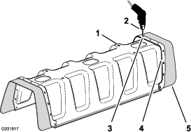
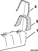
-
Remove the reinforcement plate, 11 washers (3/16 inch), and rubber cover from the 11-nozzle boom cover (Figure 231).
Note: Retain the reinforcement plate, washers, and rubber cover for installation in steps 5 and 6.
-
Align the holes in the reinforcement plate (double row) on the cover extension with the holes in the end of the 11-nozzle boom cover (Figure 232).
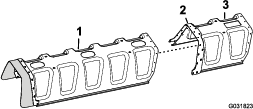
-
Secure the cover extension to the 11-nozzle section cover with 11 pop rivets (Toro Part No. 114439).
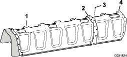
-
Align the holes in the rubber cover and the reinforcement plate (single row) that you removed in step 2 with the holes in the end of the over extension (Figure 234).
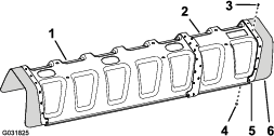
-
Secure the reinforcement plate and rubber cover to the cover extension with the 11 pop rivets (Toro Part No. 114439) and the 11 washers (3/16 inch) that you removed in step 5.
Note: Align the washers (3/16 inch) against the inside surface of the cover extension.
Installing the Support Bracket for the Center Section Cover
-
Install the 4 clip nuts that you removed in step 6 of Removing the Center Section Cover (11 Nozzle) of the Optional Covered Boom Kit onto 2 of the support bracket of the center section cover (Toro Part No. 131-3703-03) as shown in (Figure 235).
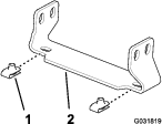
-
Install the 4 clip nuts (Toro Part No. 94-2413) onto the 2 other support bracket of the center section cover (Toro Part No. 131-3703-03) as shown in (Figure 235).
-
At the center boom section, locate the right most pair of holes in the vertical face of the truss frame with a 25 mm (1 inch) hole spacing (Figure 236).
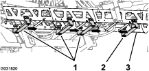
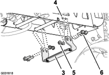
-
Align the holes in a support bracket (Toro Part No. 131-3703-03) to the holes in the center boom section that you identified in step 3 with the wide flange of the bracket to the left; refer to Figure 236.
-
Assemble the support bracket to the truss frame (Figure 236) with 4 flange-head bolts (3/8 x 1-1/4 inches—Toro Part No. 110-5050) and 4 flange locknuts (3/8 inch—Toro Part No. 104-8301).
-
Locate the remaining pairs of holes in the vertical face of the truss frame with a 25 mm (1 inch) hole spacing (Figure 236).
-
Align the holes in the 3 support bracket (Toro Part No. 131-3703-03) to the holes in the center boom section that you identified in step 6 with the wide flange of the bracket to the right (Figure 236).
-
Assemble the support brackets to the truss frame (Figure 236) with 12 flange-head bolts (3/8 x 1-1/4 inches—Toro Part No. 110-5050) and 12 flange locknuts (3/8 inch—Toro Part No. 104-8301).
-
Torque the nuts and bolts to 37 to 45 N·m (27 33 ft-lb).
Installing the Center Section Cover
-
Align the holes in the center section cover with the holes in the support brackets for the center section cover (Figure 237).
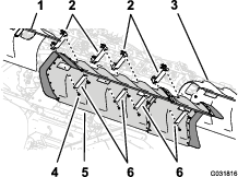
-
Align the holes in 2 of the cover straps that you removed in step 1 ofRemoving the Center Section Cover (11 Nozzle) of the Optional Covered Boom Kit with the hose in the cover and 2 of the support brackets (Figure 237).
-
Assemble the cover straps and cover to the support brackets with the 4 flange-head bolts (5/16 x 1-1/4 inches) that you removed in step 1 of Removing the Center Section Cover (11 Nozzle) of the Optional Covered Boom Kit.
-
Align the holes in the 2 cover straps (Toro Part No. 120-0629) with the 4 remaining hole in the cover and 4 remaining holes in the support brackets (Figure 237).
-
Assemble the cover straps and cover to the support brackets (Figure 237) with the 4 flange-head bolts (5/16 x 1-1/4 inches—Toro Part No. 323-36).
-
Torque the bolts to 1978 to 2542 N·cm (175 to 225 in-lb).
Connecting the Optional Tank-Rinse Kit
-
Connect the 6-pin connector of the rinse-pump harness from the 6-socket connector of the rear, main harness (Figure 238).
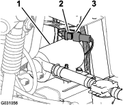
-
Align the rinse-pump cover over saddle plate for the rinse pump (Figure 239).

-
Press together the sides of the rinse-pump cover and align the tabs of the cover with the saddle plate (Figure 239).
-
Insert the tabs into the slots and release the sides of the cover (Figure 239).
Replacing the Alternator
Parts needed for this procedure:
| Belt-tensioning bracket | 1 |
| Alternator (60 A) | 1 |
| Nut (10 mm) | 1 |
| Alternator adapter harness | 1 |
Removing the Alternator (40 A)
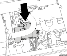
-
At the left side of the engine compartment, remove the nut (6 mm) that secures the ring terminal for the positive battery wire from the positive alternator post (Figure 241).
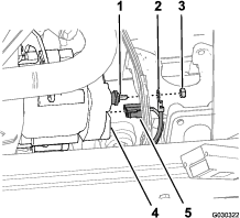
-
At the back of the alternator, remove the 2-socket connector of the wire harness for the engine from the 2-blade terminals at the alternator (Figure 241).
-
Remove the alternator lock bolt from the alternator and belt-tensioning bracket (Figure 242).
Note: Retain the alternator lock bolt for installation in Installing the Alternator (60 A).
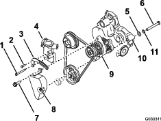
-
Remove the short tensioning-bracket bolt from the thermostat housing and belt-tensioning bracket (Figure 242).
Note: Retain the short tensioning-bracket bolt for installation in Installing the Alternator (60 A).
-
Remove the long tensioning-bracket bolt from the cylinder head, thermostat housing, and belt-tensioning bracket, and remove the belt tensioning bracket from the machine (Figure 242).
Note: Retain the long tensioning-bracket for installation in Installing the Alternator (60 A). Discard the old belt-tensioning bracket.
-
Al the back of the alternator, fully loosen the pivot bolt and remove the belt cover from the machine (Figure 242).
Note: Discard the belt cover.
-
While supporting the alternator, remove the pivot bolt, lock washer, and flat washer from the alternator and the gear case of the engine (Figure 242).
Note: Retain the pivot bolt, lock washer, and flat washer for installation in Installing the Alternator (60 A). Discard the alternator (40 A) at a parts recycling center.
-
Slip the belt off the alternator pulley and remove the alternator from the machine.
Installing the Alternator (60 A)
-
Align the holes in the new belt tension bracket with the holes in the thermostat housing (Figure 243).
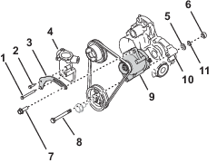
-
Assemble the belt tension bracket to the thermostat housing and cylinder head with the short tensioning-bracket bolt in the upper hole and the long tensioning-bracket bolt in the lower hole (Figure 243).
-
Torque the bolts to 29 to 33 ft-lb (39.5 to 44 N·m).
-
Align the lower hole in the alternator (60 A) to the hole in the gear case of the engine and slip the belt over the alternator pulley (Figure 243).
Note: The lower hole in the alternator is not threaded.
-
Assemble the alternator to the gear case with the pivot bolt, lock washer, and flat washer that you removed in step 7 of Removing the Alternator (40 A).
-
Loosely assemble the nut (10 mm) onto the pivot bolt (Figure 243).
-
Assemble the alternator-lock bolt through the slot in the belt tension bracket and the threaded hole in the alternator (Figure 243).
-
Rotate the alternator outward until you attain belt tension that allows the belt to deflect 10 mm (3/8 inch) when 4.5 kg (10 lb) force is applied to the belt, midway between the pulleys (Figure 243).
-
Torque the alternator-lock bolt, and the pivot bolt and nut (10 mm) to 64 to 71 N·m (47 to 53 ft-lb).
Installing the Alternator Adapter Harness
-
Align the socket connector of the alternator adapter harness with the pins of the electrical connector on the alternator (60 A) and push the connectors together the lock on the connector snaps securely (Figure 244).
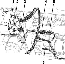
-
Align the 2-blade connector of the alternator adapter harness with the 2-socket connector of the wire harness for the machine that you removed in step 2 of Removing the Alternator (40 A) and push the connectors together until the lock on the connectors snaps securely (Figure 244).
-
At the wire harness of the machine, assemble the ring terminal onto the alternator post, and secure the terminal with the nut (6 mm) that you removed in step 1 of Removing the Alternator (40 A).
Completing the Installation of the GeoLink Spray System Finishing Kit
-
Move the prop rod for the seats into the slots and tilt the seats down.
-
Connect the positive (red) cable to the positive (+) battery post and the negative (black) cable to the negative (–) battery post using the bolts and nuts; refer to Figure 3 in the instructions for Disconnecting the Battery.
-
Slide the insulator boot over both battery posts; refer to Figure 3 in the instructions for Disconnecting the Battery.
-
Install the battery cover and secure it with the strap; refer to Figure 2 in the instructions for Disconnecting the Battery.
Operation
Think Safety First
Carefully read all safety instructions and symbols in the safety section. Knowing this information could help you or bystanders avoid injury.
Caution
This machine produces sound levels that can cause hearing loss through extended periods of exposure.
Wear hearing protection when operating this machine.
Use protective equipment for your eyes, ears, hands, feet, and head.
Operating the Shutoff Valve
-
Park the machine on a level surface, turn the booms off, and engage the parking brake.
Warning
Driving the machine while using the hand sprayer can cause loss of control, resulting in injury or death.
Do not operate the hand sprayer while you are driving the machine.
-
Perform the following for the spray wand or hose reel kits:
-
Optional Hand Spray-Wand Kit—at the right side of the machine, ensure that the trigger lock on the spray gun is locked; refer to switching from boom spray mode to hand spray mode in the Installation Instructions for the Hand Spray-Wand Kit.
-
Optional Electric Hose-Reel Kit or the Pivoting Hose-Reel Kit—at the back of the machine, ensure that the trigger lock on the spray gun is locked; refer to switching from boom spray mode to hand spray mode in the Installation Instructions for the Electric Hose-Reel Kit or the Pivoting Hose-Reel Kit.
-
-
Rotate the green handle of the shutoff valve counterclockwise 90 degrees to the OPEN position (Figure 246).
Note: To shut off the flow of fluid to the hand-spray wand of hose reel, rotate the green handle of the shutoff valve clockwise 90 degrees to the CLOSED position (Figure 246).
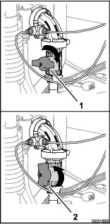
-
Set the master-boom switch to the ON position.
-
Adjust the engine speed to the desired rpm, then set the neutral engine-speed lock.
-
Manually set the sprayer system to your desired pressure for spray gun operation; refer to Changing the Pressure Manually for the Hose Reel and Eductor video on the USB drive that you received with the GeoLink Precision Spray System.
Note: Do not use a pressure setting higher than 1034 kPa (150 psi) with the hand sprayer.
Operating the Controls
-
Compressor on/off switch—Use this switch to run the compressor for the foam marker system.
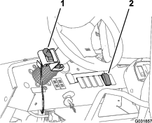
-
Foam-control switch—Use this switch to control which boom from which foam flows.
-
Move the paddle down to apply foam from the left boom section.
-
Move the paddle to the center position apply foam from the left and right boom sections.
-
Move the paddle up to apply foam from the right boom section.
-
Operating the Fluid-Shutoff Valve
The following procedure assumes the following operational states exist for the standard tank agitation: The sprayer is started and running, the pump is engaged and set to the desired pressure, and the throttle is in the mid-range position.
Note: Close the eductor hopper valve and hopper rinse ball valve(s) before starting the eductor.
-
Lower the eductor; refer to raising and lowering the eductor in the chemical pre-mix kit Installation Instructions.
-
Open the lid to check for foreign objects which may hinder performance or contaminate the system; refer to starting the eductor in the Installation Instructions for the chemical pre-mix kit.
-
Close and lock the lid by turning the cover clockwise; refer to starting the eductor in the Installation Instructions for the chemical pre-mix kit.
-
Open the fluid-shutoff valve for the eductor by rotating the handle counterclockwise to the OPEN position (Figure 248).
Note: To shut off the flow of fluid to the eductor, rotate the handle of the fluid-shutoff valve clockwise 90 degrees to the CLOSED position (Figure 248).
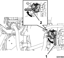
-
Open the hopper valve (red handle) located on the bottom of the hopper; refer to starting the eductor in the Installation Instructions for the chemical pre-mix kit.
-
Unlock and open the lid slowly by turning the cover counterclockwise; refer to starting the eductor in the Installation Instructions for the chemical pre-mix kit.
-
Fill the hopper of the eductor; refer to Loading Liquid or Powdered Chemical into the Hopper in the Installation Instructions for the chemical pre-mix kit.