


Maintenance
Note: Determine the left and right sides of the machine from the normal operating position.
Recommended Maintenance Schedule(s)
| Maintenance Service Interval | Maintenance Procedure |
|---|---|
| After the first 8 hours |
|
| After the first 10 hours |
|
| Before each use or daily |
|
| Every 25 hours |
|
| Every 50 hours |
|
| Every 100 hours |
|
| Before storage |
|
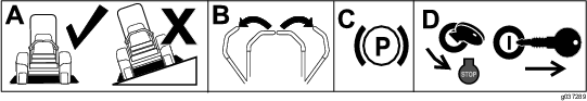
Warning
If you leave the key in the ignition switch, someone could accidently start the engine and seriously injure you or other bystanders.
Remove the key from the ignition and disconnect the wire from the spark plug before you do any maintenance. Set the wire aside so that it does not accidentally contact the spark plug.
Warning
Engines can become hot when they are operating. Burns can occur from contacting hot surfaces.
Allow engines, especially the muffler, to cool before touching.
Warning
Debris, such as leaves, grass, or brush can catch fire. A fire in the engine area can cause personal injury and property damage.
-
Keep the engine and muffler area free of debris accumulation.
-
Take care when opening the bagger cover to keep debris from falling onto the engine and muffler area.
-
Allow the machine to cool before storing it.
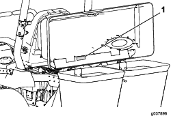
Cleaning the Hood Screen
| Maintenance Service Interval | Maintenance Procedure |
|---|---|
| Before each use or daily |
|
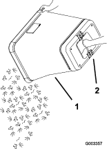
The screens need to be cleaned before each use.
-
Park the machine on a level surface.
-
Disengage the blade-control switch, engage the parking brake, and move the motion-control levers outward to the NEUTRAL-LOCK position.
-
Shut off the engine and remove the key.
-
Open the bagger hood.
-
Clean the debris from the screen.
-
Close the bagger hood.
Inspecting the Bagger Attachment
| Maintenance Service Interval | Maintenance Procedure |
|---|---|
| After the first 10 hours |
|
| Before storage |
|
Inspect the bagger attachment after the first 10 hours of operation, and monthly thereafter.
-
Check the chute, discharge tube, and the bagger top. Replace these parts if they are cracked or broken.
-
Tighten all nuts, bolts, and screws.
-
Inspect all fasteners and latches; replace any missing or damaged.
-
Inspect the grass bags for deterioration.
Warning
You or bystanders could be severely injured by flying debris or thrown objects that may pass through torn, worn, or deteriorated grass bags.
-
Check the grass bags for holes, rips, wear, and other deterioration.
-
Do not wash the grass bags.
-
If the bag has deteriorated, install new grass bags supplied by the manufacturer of this bagger attachment.
-
Cleaning the Bagger and Bags
| Maintenance Service Interval | Maintenance Procedure |
|---|---|
| Before each use or daily |
|
The bagger needs to be cleaned daily.
-
Wash the inside and outside of the bagger hood, bags, tube, and the underside of the mower deck. Use a mild automotive detergent to remove dirt.
-
Ensure that you remove matted grass from all parts.
-
After washing all the parts, let them dry thoroughly.
Note: With all parts installed, start and run the machine for approximately 1 minute to assist in drying.
Inspecting the Blower Belt
| Maintenance Service Interval | Maintenance Procedure |
|---|---|
| After the first 8 hours |
|
| Every 25 hours |
|
Check belts for cracks, frayed edges, burn marks, or any other damage. Replace any belts that are damaged.
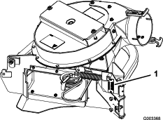
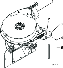
Replacing the Blower Belt
Blower Models 78483 to 78488
-
Park the machine on a level surface.
-
Disengage the blade-control switch, engage the parking brake, and move the motion-control levers outward to the NEUTRAL-LOCK position.
-
Shut off the engine and remove the key.
-
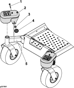
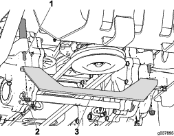
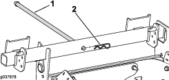
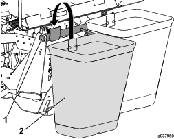
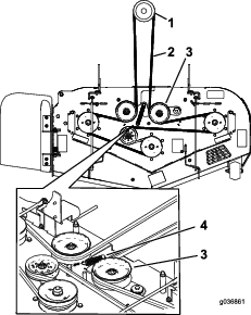
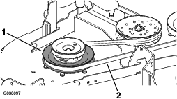
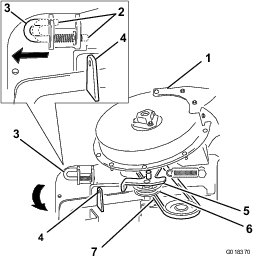
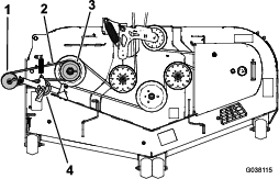
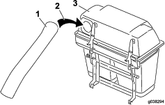
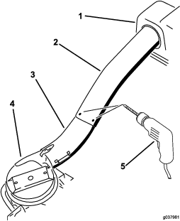
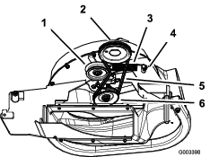
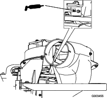
Pull back on the spring-loaded idler pulley to relieve the belt tension (Figure 58).
-
Remove the existing blower belt.
-
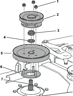
Install the new belt around the blower pulley (Figure 58).
-
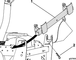
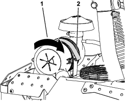
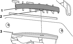
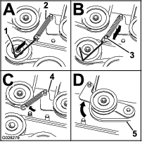
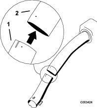
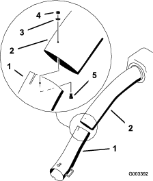
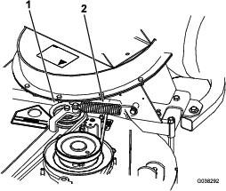
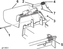
Install the spring as shown in Figure 59.
-
Install the belt onto the spring-loaded idler pulley (Figure 59).
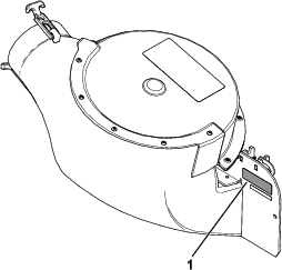
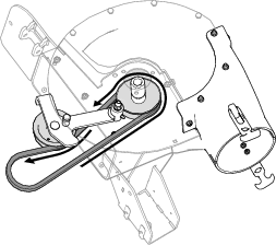
Blower Models 78401 to 78406
-
Park the machine on a level surface.
-
Disengage the blade-control switch, engage the parking brake, and move the motion-control levers outward to the NEUTRAL-LOCK position.
-
Shut off the engine and remove the key.
-
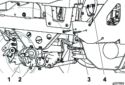
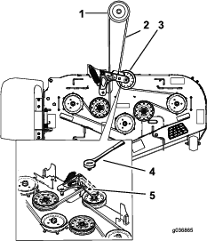
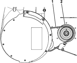
Pull back on the spring-loaded idler pulley to relieve the belt tension.
-
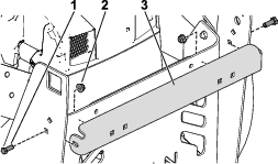
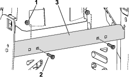
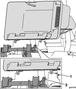
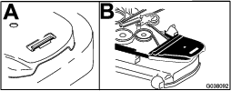
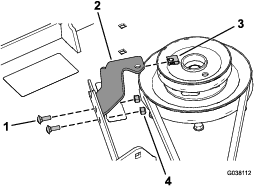
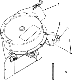
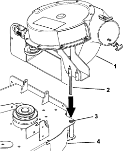
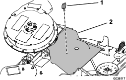
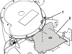
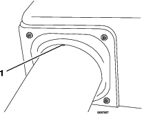
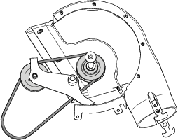
Remove the existing blower belt (Figure 60 and Figure 61).
-
Install the new belt around the blower pulley; refer to Installing the Blower Belt, Spring, and Blower-Belt Cover.
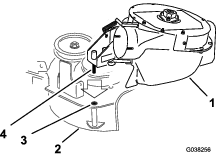
Greasing the Idler Arm for Blower Models 78483 to 78488
| Maintenance Service Interval | Maintenance Procedure |
|---|---|
| Every 50 hours |
|
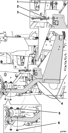
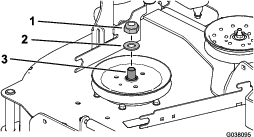
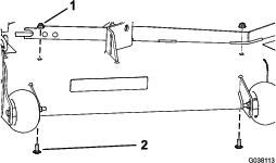
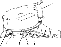
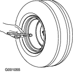
Grease the bagger belt idler arm (Figure 62) every 50 hours.
Inspecting the Bagger
| Maintenance Service Interval | Maintenance Procedure |
|---|---|
| After the first 8 hours |
|
| Every 100 hours |
|
-
Park the machine on a level surface.
-
Disengage the blade-control switch, engage the parking brake, and move the motion-control levers outward to the NEUTRAL-LOCK position.
-
Shut off the engine and remove the key.
-
Check the upper tube, lower tube, bagger hood, and the blower assembly. Replace these parts if they are cracked or broken.
-
Check the bags, bagger frame, and screen. Replace any parts that are cracked or broken.
-
Tighten all nuts, bolts, and screws.
Inspecting the Mower Blades
-
Inspect the mower blades regularly and whenever a blade strikes a foreign object.
-
If blades are badly worn or damaged, install new blades. Refer to your machine Operator's Manual for complete blade maintenance.
Selecting the Mower Blades
In most mowing conditions, the standard high lift blades provide the best bagging performance.
The Toro Atomic blade is recommended for bagging leaves in dry conditions. In dry dusty conditions, the medium lift or low lift blades reduce dust and dirt blowout while providing effective bagging air flow.
Contact an Authorized Service Dealer for the proper blades for different mowing conditions.
Refer to the machines Operator's Manual for more information on installing blades.
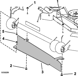
Replacing the Grass Deflector
Warning
An uncovered discharge opening could allow the machine to throw objects at you or bystanders, resulting in serious injury. Also, contact with the blade could occur.
-
Never operate the machine without a grass deflector, a mulch plate, or a bagger system installed.
-
Ensure that the grass deflector is in the down position.
-
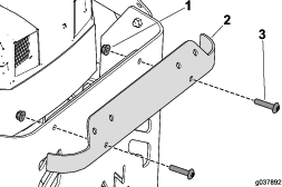
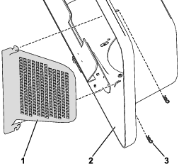
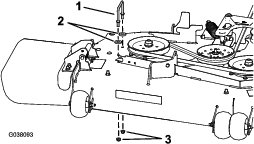
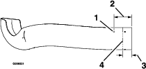
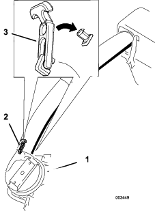
Place one end of the spring behind the deck edge and the other end on the grass deflector (Figure 63).
-
Use the bolt and nut to secure the grass deflector assembly to the mower deck (Figure 63).
-
Place the J-hook end of the spring around the grass deflector (Figure 63).
Important: The grass deflector must be able to lower down into position. Lift the deflector up to test that it lowers into the full down position.