Maintenance
Replacing Fuses
Replacing the Fuse
-
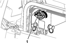
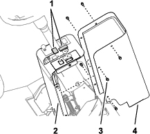
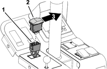
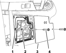
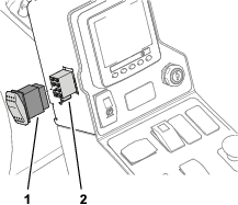
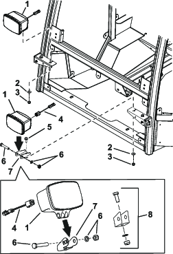
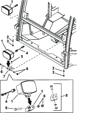
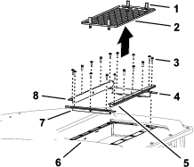
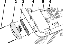
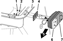
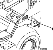
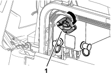
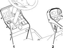
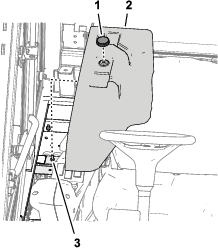
Remove the 2 socket-head bolts (1/4 x 3/4 inch) and 2 washers (1/4 inch) that secure the controller cover for the power center to the relay mount, and remove the cover (Figure 51).
-
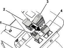
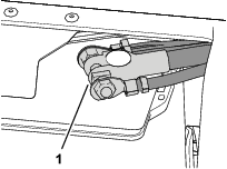
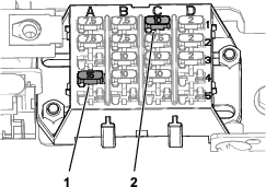
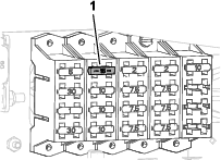
Replace the open (blown) fuse for the road light circuit, at the fuse-block slot at column in row or column in row (Figure 52).
-
Assemble the controller cover to the relay mount with the 2 socket-head bolts (1/4 x 3/4 inch) and 2 washers (1/4 inch) that you removed in step 1 (Figure 51).
Replacing the Fuse
-
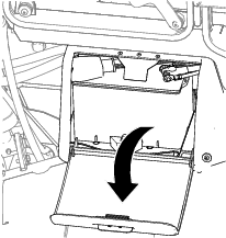
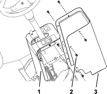
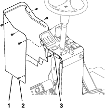
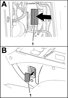
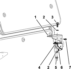
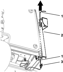
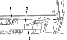
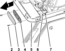
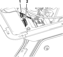
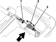
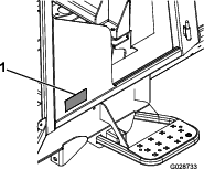
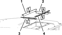
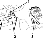
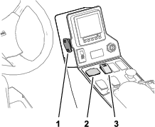
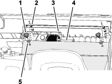
Remove the knob that secures the cover for the power center to the stud on the power-center bracket, and remove the cover (Figure 53).
-
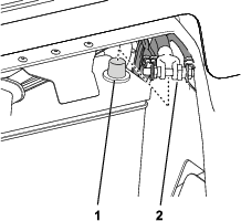
Replace the open (blown) fuse for the road light circuit at fuse-block slot at column in row (Figure 54).
-
Align the hole in the cover for the power center with the stud on the power-center bracket (Figure 53).
-
Secure the cover to the stud with the knob that you removed in step 1 (Figure 53).
Replacing the Fuses
-
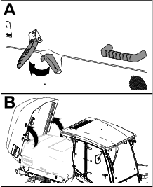
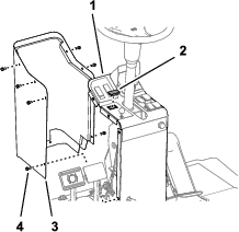
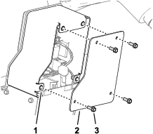
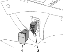
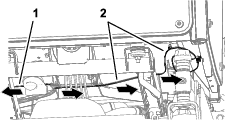
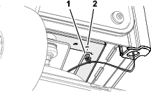
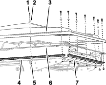
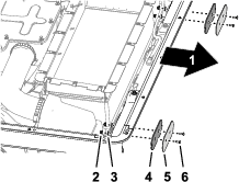
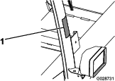
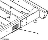
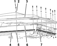
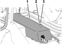
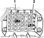
Remove the 2 knobs and 2 washers that secure the cover to the flange of the electrical plate for the power center, and remove the cover (Figure 55).
Note: Retain the 2 star washers for installation of the cover.
-
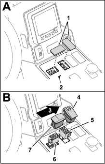
Replace the open (blown) fuse for the following circuits:
-
Road lights fuse (15 A)—fuse-block slot at column in row
-
Hazard flasher fuse (10 A)—fuse-block slot at column in row
-
-
Align the holes in the cover to the holes in the flange of the electrical plate (Figure 55).
-
Secure the cover to the power center with the 2 knobs, 2 washers, and 2 star washers that you removed in step 1 (Figure 55).