Introduction
Read this information carefully to learn how to operate and maintain your product properly and to avoid injury and product damage. You are responsible for operating the product properly and safely.
Visit www.Toro.com for product safety and operation training materials, accessory information, help finding a dealer, or to register your product.
Whenever you need service, genuine Toro parts, or additional information, contact an Authorized Service Dealer or Toro Customer Service and have the model and serial numbers of your product ready. Figure 1 identifies the location of the model and serial numbers on the product. Write the numbers in the space provided.
This manual identifies potential hazards and has safety messages identified by the safety-alert symbol (Figure 2), which signals a hazard that may cause serious injury or death if you do not follow the recommended precautions.

This manual uses 2 words to highlight information. Important calls attention to special mechanical information and Note emphasizes general information worthy of special attention.
Safety
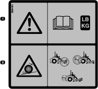
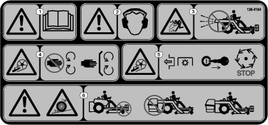
Safety and Instructional Decals
 |
Safety decals and instructions are easily visible to the operator and are located near any area of potential danger. Replace any decal that is damaged or missing. |

Installation
Note: Determine the left and right sides of the machine from the normal operating position.
Preparing the Machine
-
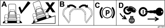
Park the machine on a level surface.
-
Move the motion-control levers to the NEUTRAL-LOCK position.
-
Engage the parking brake.
-
Shut off the engine and remove the key.
Removing the Existing Belt Cover, Bracket, and Discharge Chute
Note: Clean the area around the belt cover before removing it.
-
Lower the mower deck to the lowest height-of-cut position.
-
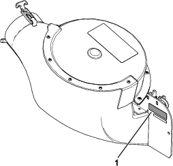
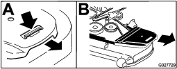
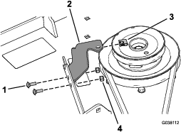
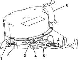
Remove the right belt cover (Figure 4).
-
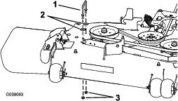
Remove the right belt-cover bracket, 2 washers (60-inch mower deck only), and 2 flange nuts from the mower deck (Figure 5).
Note: Retain the hardware that you removed during this procedure so that it is available for changeover.
-
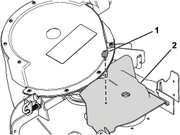
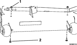
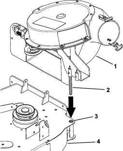
Remove the locknut, bolt, spring, and spacer securing the deflector to the pivot brackets (Figure 6).
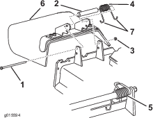
-
Remove the grass deflector (Figure 6).
Installing the Blower-Pulley Assembly and Belt-Cover Bracket
Parts needed for this procedure:
| Blower-pulley assembly | 1 |
| Belt-cover bracket | 1 |
| Speed nut | 1 |
| Carriage bolt (1/4 x 3/4 inch) | 2 |
| Locknut (1/4 inch) | 2 |
| Locknut (3/8 inch) | 3 |
| Blower pulley | 1 |
| Locknut (3/4 inch) | 1 |
| Washer | 1 |
| Pulley mount | 1 |
-
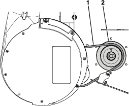
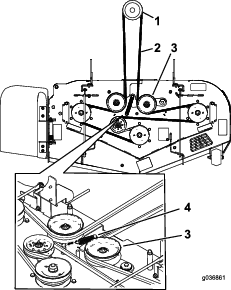
On the machine, remove the spring tension from the spring-loaded idler pulley; refer to Figure 7 or Figure 9.
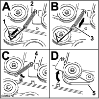
Note: For blower Models 78401, 78402, and 78403, use the spring-removal tool (Toro Part No. 92-5771) to remove the spring from the mower-deck post (Figure 8).
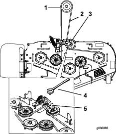
Note: For blower Models 78404, 78405, and 78406, use a ratchet in the square hole in the idler arm to remove tension on the idler spring (Figure 9).
-
Remove the belt from the right mower-deck pulley.
-
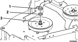
Use a wrench (1-1/2 inches) to hold the spindle shaft, as you remove the locknut (3/4 inch) and washer from the spindle shaft (Figure 10).
Note: Set aside the locknut (3/4 inch) and washer for blower Models 78404, 78405, and 78406.
-
Use a wrench (1-1/2 inches) to hold the spindle shaft, as you install the double pulley onto the right spindle shaft.
-
For blower Models 78401, 78402, and 78403, perform the following procedure:
-
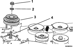
Use the locknut (3/4 inch) and washer to secure the new double pulley onto the right spindle shaft (Figure 11).
-
Torque the locknut (3/4 inch) to 176 to 217 N∙m (130 to 160 ft-lb).
-
-
For blower Models 78404, 78405, and 78406, perform the following procedure:
-
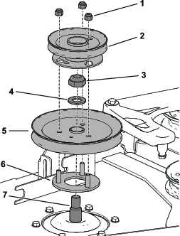
Insert the threaded studs on pulley mount through the holes in the deck pulley (Figure 12).
-
Use the locknut (3/4 inch) and washer that you set aside earlier to secure the deck pulley to the spindle shaft (Figure 12).
-
Torque the locknut (3/4 inch) to 176 to 217 N∙m (130 to 160 ft-lb).
-
Arrange the blower pulley onto the threaded studs and loosely install the locknut (Figure 12).
-
Rotate the blower pulley clockwise until it stops.
-
Torque the 3 locknuts to 18 N∙m (13 ft-lb).
-
-
-
Ensure that the blade bolt is torqued to 115 to 149 N∙m (85 to 110 ft-lb).
-
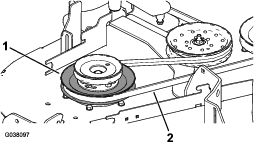
Install the mower belt around the lower pulley of the double pulley (Figure 13).
-
Install the belt-cover bracket to the mower deck using 2 carriage bolts (1/4 x 3/4 inch) and 2 locknuts (1/4 inch) as shown in Figure 14.
-
Install the speed nut onto the belt-cover bracket (Figure 14).
-
Install the mower deck belt around the spring-loaded idler pulley (Figure 7 or Figure 9).
-
Use the spring-removal tool (Toro Part No. 92-5771) to attach the spring to the spring-loaded idler pulley.
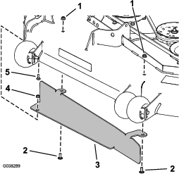
Installing the Baffle
Parts needed for this procedure:
| Baffle | 1 |
| Carriage bolt (5/16 x 7/8 inch) | 1 |
| Flange nut (5/16 inch) | 1 |
| Carriage bolt (3/8 x 7/8 inch) | 2 |
| Flange nut (3/8 inch) | 2 |
Installing the Blower Assembly
Parts needed for this procedure:
| Blower assembly | 1 |
| Blower belt | 1 |
| Pivot pin | 1 |
| Roll pin | 1 |
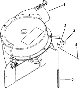
Verify that the pivot pin is secured on the blower assembly in the correct location (Figure 17).
-
If you have a 48-inch or 52-inch mower deck, install the pivot pin in the front hole (Figure 17).
-
If you have a 60-inch mower deck, install the pivot pin in the rear hole (Figure 17).
-
Align the pivot pin on the blower with the pivot-pin hole in the mower deck (Figure 18).
-
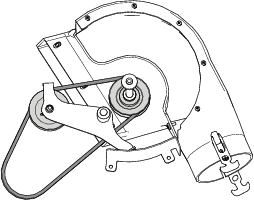
Install the belt around the pulleys inside the blower (Figure 19).
-
Lower the blower and slide the pivot pin into the pivot hole (Figure 18).
Note: Ensure that the belt remains positioned in the blower pulley.
-
Move the latch pin from the locking position to the open position (Figure 20).
-
Close the blower assembly and align the latch pin with the hole in the chute bracket (Figure 20).
-
Move the latch pin to the locking position.
Note: Ensure that the latch pin extends through the hole in the chute bracket.
Note: Ensure that the latch firmly holds the blower assembly against the mower deck, but you can release it by hand.