Installation
Disconnecting the Battery
-
Park the machine on a level suface.
-
Engage the parking brake.
-
Lower the cutting units.
-
Shut off the engine and remove the key.
-
Disconnect the battery; refer to your machine Operator’s Manual.
Drilling the Mounting Holes
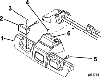
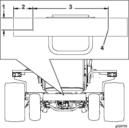
Drilling the Holes for the Headlights and the Wire Harness
-
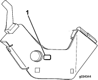
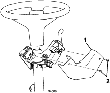
Remove the nuts from the 2 carriage bolts securing the headlights to the traction-unit frame (Figure 1).
-
Remove the 2 self-tapping bolts securing the top of the platform shroud to the frame (Figure 1).
-
Unplug the headlight connectors and remove the platform shroud from the frame (Figure 1).
-
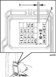
Drill a 38 mm (1-1/2 inch) hole in the platform shroud in the location shown in Figure 1.
-
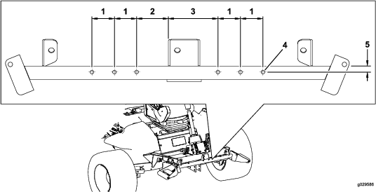
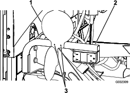
Using the dimensions in Figure 2, locate and drill 6 holes (1.0 cm) through both walls of the roller-support tube.
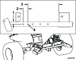
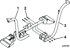
Drilling the Holes for the Horn Bracket
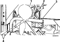
Using the dimensions in Figure 3, locate and drill 2 holes (7 mm) through both walls of the roller-support tube.
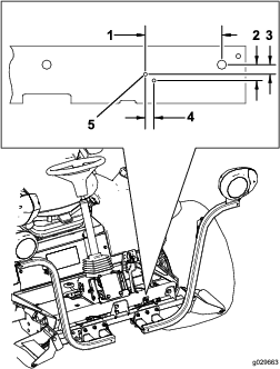
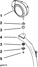
Drilling the Holes in the Front Footrest for the Brake-Pedal Switch
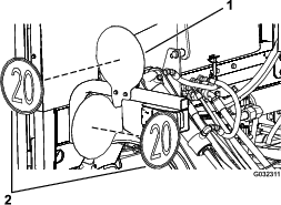
Using the dimensions in Figure 4, locate and drill 2 holes (7 mm) through the front footrest.
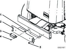
Drilling the Mounting Holes in the Rear Bumper for the License Plate
Using the dimensions shown in Figure 5, locate and drill 2 holes (9/32 inch) through the outside wall of the rear bumper.
Installing the Headlights
Parts needed for this procedure:
| Right headlight bracket | 1 |
| Left headlight bracket | 1 |
| Bolt (3/8 x 2-1/2 inches) | 6 |
| Flange nut (3/8 inch) | 6 |
| Washer (3/8 x 7/8 inches) | 8 |
| Rubber hanger | 2 |
| Spacer | 4 |
| Bolt (5/16 x 1-5/8 inches) | 4 |
| Flange nut (5/16 inch) | 4 |
| Right headlight assembly | 1 |
| Left headlight assembly | 1 |
| Bent-plate bracket | 2 |
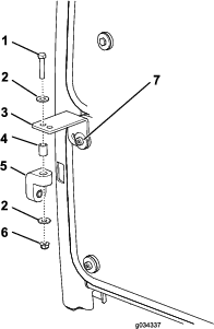
Installing the Headlight Bracket to a ROPS Model
-
Fasten the left and right headlight brackets to the front of the roller-support tube with 6 bolts (3/8 x 2-1/2 inches) and 6 flange nuts (3/8 inch) as shown in Figure 6.
Note: Position the bolts so that the flange nuts are toward the front of the traction unit.
-
Fasten the left and right headlights to the headlight brackets (Figure 7) with the fasteners supplied with the lights.
Note: Ensure that the turn-signal lens on the headlight is positioned toward the outside of the traction unit.
-
Tighten the locknut to firmly hold the headlight assembly to the headlight bracket.
Note: Do not overtighten the locknut.
Installing the Headlight Bracket to a Cab Model
-
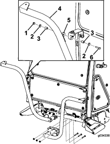
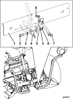
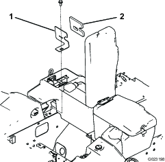
Install a bent-plate bracket onto each of the upper corners of the lower front panel of the cab with the existing screws as shown in Figure 8.
-
Loosely install a rubber hanger to each bent-plate bracket with a bolt (5/16 x 1-5/8 inch), 2 washers (3/8 inch), a spacer, and a flange nut (5/16 inch) as shown in Figure 8.
-
Loosely install the left and right headlight brackets to the front of the roller-support tube with 6 bolts (3/8 x 2-1/2 inches) and flange nuts (3/8 inch). Position the brackets as shown in Figure 9.
Note: Ensure that the holes in the bent-plate brackets align with the holes in the rubber hangers.
-
Fasten the left and right headlight assemblies to the headlight brackets (Figure 7) with the fasteners supplied in the kit.
Note: Ensure that the turn-signal lens on the headlight is positioned toward the outside of the traction unit.
-
Tighten the locknut to firmly hold the headlight assembly to the headlight-assembly bracket.
Note: Do not overtighten the locknut.
Note: You cannot use the front and rear cab lights for CE applications. Disable the front and rear cab lights as follows:
-
Front—Remove the lights from the cab roof and disconnect the wires from the lights. Install the lights into the cab.
-
Rear—Remove the screws securing the lenses to the lights. Remove the bulbs from the lights and install the lenses to the lights.
Installing the Horn
Parts needed for this procedure:
| Horn | 1 |
| Horn bracket | 1 |
| Bolt (3/8 x 5/8 inch) | 1 |
| Flange nut (3/8 inch) | 1 |
| Bolt (1/4 x 2 inches) | 2 |
| Nut (1/4 inch) | 2 |
Installing the Relay Switch
Parts needed for this procedure:
| Relay switch | 1 |
| Serrated hex-head flange bolt (#8 x 1/2 inch) | 1 |
| Locknut (#8) | 1 |
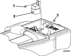
Secure the relay switch under the battery cover with a serrated hex-head flange bolt (#8 x 1/2 inch) and a locknut (#8) at the location shown in Figure 11.
Note: Do not overtighten the bolt.
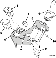
Installing the Flasher Module and Switches on the Column Bracket
Parts needed for this procedure:
| Column bracket | 1 |
| Flasher module | 1 |
| On-Off-On rocker switch | 1 |
| Beacon switch | 1 |
| Paddle switch | 1 |
| Horn switch | 1 |
| Horn button | 1 |
| Horn decal (Part No. 104-6957) | 1 |
| Hex socket button-head screw | 1 |
| Speed nut | 2 |
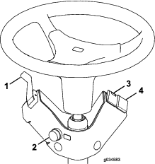
Installing the Column-Bracket Assembly onto the Steering Column
Parts needed for this procedure:
| Steering-column bracket | 1 |
| Column mount bracket | 1 |
| Carriage bolt (3/8 x 3/4 inch) | 2 |
| Flange nut (3/8 inch) | 2 |
| Foam strip | 1 |
| Cable tie | 1 |
-
Install the foam strip on the steering column as shown in Figure 14.
-
Insert the cable tie through the slots in the column mount bracket so that the ends are outward, but do not tie them.
-
Install the steering-column bracket onto the steering column with the mounting bracket, 2 carriage bolts, and 2 flange nuts (Figure 14).
Important: Ensure that the top of the steering-column bracket is 21 mm (0.83 inch) below the top of the steering column.
Important: Torque the fasteners to 19 to 24 N∙m (14 to 18 ft-lb). Do not overtighten the carriage bolts; otherwise, you may deform the steering-column bracket.
Installing the Brake-Sensor Bracket
Parts needed for this procedure:
| Carriage bolt (#10 x 5/8 inch) | 1 |
| Locknut (#10) | 1 |
| Sensor plate | 1 |
| Flange nut (1/4 inch) | 2 |
| Brake-sensor bracket | 1 |
| Bolts (1/4 x 3/4 inch) | 2 |
| Slotted screw (#6 x 1 inch) | 2 |
| Washer (#6) | 4 |
| Brake sensor | 1 |
| Locknut (#6) | 2 |
Note: This procedure is only for machines with halogen headlights. Use Figure 15 to determine if you have halogen headlights.
-
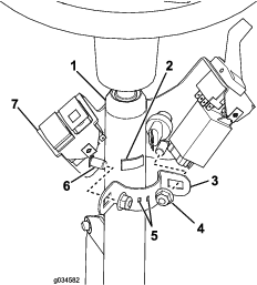
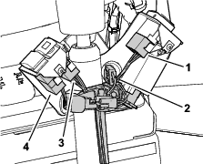
Disassemble the proximity-sensor assembly on the brake-pedal lever (Figure 16) and set aside all the parts except the proximity sensor.
-
Assemble the proximity-sensor assembly to the brake lever using the carriage bolt (#10 x 5/8 inch), brake-sensor plate, proximity sensor, and locknut (#10) as shown in Figure 16.
Note: Ensure that you do not overtighten the bolts. Overtightening the bolts will damage the sensor.
-
Locate the brake-sensor bracket mounting holes on the front footrest and loosely install the brake-sensor bracket to the front footrest using 2 bolts (1/4 x 3/4 inch) and 2 flange nuts (1/4 inch).
Note: You will need to move the brake-sensor bracket up or down to align the brake sensor to the brake-sensor plate (Figure 17).
-
Loosely install the brake sensor to the brake-sensor bracket with the 2 slotted screws (#6 x 1 inch), 2 washers, and 2 flange nuts (Figure 17).
-
Align the brake sensor in or out and the brake-sensor bracket up or down so that the switch on the brake sensor is pressing against the sensor plate.
-
Complete the brake-sensor assembly installation by tightening all of the mounting hardware.
-
Tighten the 2 slotted screws (#6 x 1 inch) and 2 flange nuts to firmly secure the brake sensor to the brake-sensor bracket.
Note: Ensure that you do not overtighten the screws. Overtightening the screws will damage the sensor.
-
Tighten the bolts (1/4 x 3/4 inch) and 2 flange nuts (1/4 inch) holding the brake-sensor bracket to the front footrest to 1,017 to 1,243 N∙cm (90 to 110 in-lb).
-
Important: After you complete the installation of the light kit, verify that the brake sensor activates the brake lights when the brake pedal is pressed. Realign the brake sensor if necessary.
Installing the Rear Lamps
Parts needed for this procedure:
| Left light bracket | 1 |
| Right light bracket | 1 |
| Screw (5/8 x 3 inches) | 4 |
| Flat washer | 4 |
| Jam nut (5/8 inch) | 2 |
| Rear-lamp assembly | 2 |
-
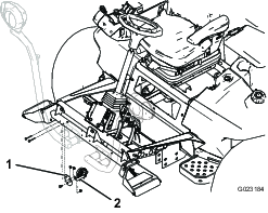
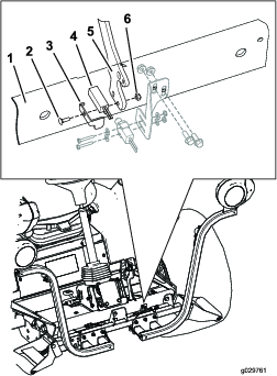
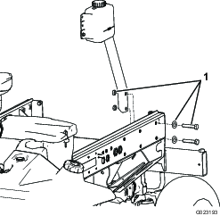
Remove the 2 bolts, 2 washers, and 2 nuts securing the reservoir-mounting bracket to the left frame rail (Figure 18).
Note: Stabilize the reservoir and bracket to prevent them from falling.
-
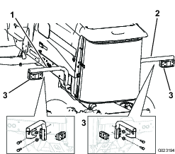
Secure the left light bracket to the bracket and frame with 2 bolts (5/8 x 3 inches), 2 flat washers and 2 jam nuts as shown in (Figure 19).
Note: The left and right light brackets are different. Ensure that you use the correct mount.
-
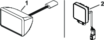
Mount the rear lamp to light bracket with the bolts and nuts included with the light (Figure 19).
Note: Ensure that the light is positioned so that the plug is through the hole in the light bracket and the amber end is toward the outside of the traction unit.
-
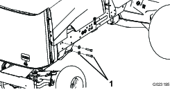
Remove the 2 rear bolts and 2 washers from the right frame rail (Figure 20).
-
Secure the right light bracket to the frame with 2 bolts (5/8 x 3 inches) and 2 flat washers (Figure 19).
Installing the License-Plate Bracket
Parts needed for this procedure:
| Plate light | 1 |
| Plate bracket | 1 |
| Screw (#10 x 5/8 inch) | 2 |
| Locknut (#10) | 2 |
| Self-tapping screw (5/16 x 1/2 inch) | 2 |
-
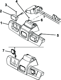
Secure the plate light to the license-plate bracket with 2 screws (#10 x 5/8 inch) and 2 locknuts (Figure 21).
Note: Do not overtighten the screws. Ensure that the lens points downward and the wires are inserted through the hole in the license-plate bracket.
-
Mount the license-plate bracket to the rear bumper with 2 self-tapping screws (5/16 x 1/2 inch) as shown in Figure 21.
Note: Position the license-plate bracket as shown in Figure 21.
Installing the Wire Harness
Parts needed for this procedure:
| Wire harness | 1 |
| Switch-panel-enclosure cover | 1 |
| Screw (#10 x 1/2 inch) | 3 |
| Mounting pad | 3 |
| Cable tie | 11 |
| Jumper wire harness (LED headlights only) | 2 |
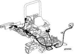
Use the following instructions and illustrations to route and connect the wire harness.
-
Remove the flange-head screw securing the compartment clamp and seal to the traction unit (Figure 23).
Note: Remove the clamp and seal to gain access to the fuse compartment.
-
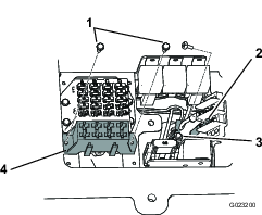
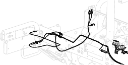
From under the right side of the traction unit, route the fuse-block section of the wire harness up to and into the opening in the fuse compartment (Figure 24).
Important: When routing the wire harness, do not pull it across sharp edges, which may damage the wires. Wires must not contact hot or moving parts. Secure the wire harness with cable ties.
-
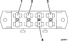
Mount the wire-harness-fuse block next to the existing fuse block with the 2 self-tapping screws (#8 x 1/2 inch) included with the wire harness (Figure 25).
Note: Do not overtighten the screws.
-
Connect the small-ring terminal from the wire harness to 1 of the screws on the ground-block terminal (Figure 25).
-
Connect the large-ring terminal, from the wire harness, to the stud on the junction block (Figure 25).
-
Install the compartment clamp and seal to the traction unit with the flange-head screw (Figure 23).
-
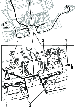
Route the front end of the wire harness under the operator platform to the front of the traction unit (Figure 26).
Note: Use Figure 27 or Figure 15 to determine which headlight you have.
-
For machines with LED headlights, install the jumper wire harnesses shown in Figure 26.
-
Thread each harness connector through the appropriate headlight bracket and connect it to the headlight (Figure 26).
-
Plug the wire harness lead, with the 2 connectors, into the horn (Figure 26).
-
Position the platform shroud on top of the frame (Figure 27).
-
Plug the light-kit wire harness connectors into the shroud headlights (Figure 27).
-
Secure the shroud and the headlights to the frame with the 2 carriage bolts and nuts you previously removed (Figure 27).
-
Route the wire harness to the column-bracket assembly on the steering column.
-
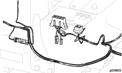
Plug the connectors into the flasher module, horn, turn signal, and hazard switches (Figure 28).
-
Install the cover onto the column-bracket assembly with 2 hex socket button-head screws as shown in Figure 29.
-
Secure the wire harness to the column using the cable tie inserted into the slots in the column mount bracket; refer to Figure 14.
-
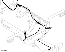
Route the right rear wire harness under the right side of the traction unit to the right, rear light (Figure 30).
-
Plug the wire-harness connector into the light connector.
-
Route the left, rear wire harness under the left side of the traction unit to the left, rear light (Figure 30).
-
Plug the wire-harness connector into the light connector.
-
Route the wire harness to the registration-plate light and plug the wire-harness connector into the light connector (Figure 31).
Important: Secure the wire harness with cable ties so that it does not contact any hot or moving parts.
-
Install any parts that were removed from the traction unit to route the wire harness.
Installing the Fuses and Decal
Installing the Decal-Mounting Plates
Parts needed for this procedure:
| Plate | 2 |
| Decal | 4 |
| Hex-head screw (1/4 x 2-1/2 inches) | 4 |
| Locknut (1/4 inch) | 4 |
Connecting the Battery
Connect the battery; refer to your machine Operator’s Manual.
Operation
Controls
Aiming the Headlights
-
Loosen the mounting nuts and position each headlight so that it points straight ahead.
-
Tighten each mounting nut just enough to hold the headlight in position.
-
Place a flat piece of sheet metal over the face of the headlight.
-
Mount a magnetic protractor onto the plate.
-
While holding the assembly in place, carefully tilt the headlight downward 3 degrees, then tighten the nut.
-
Repeat the procedure for the other headlight.