Introduction

Read this information carefully to learn how to operate and maintain your product properly and to avoid injury and product damage. You are responsible for operating the product properly and safely.

You may contact Toro directly at www.Toro.com for product safety and operation training materials, accessory information, help finding a dealer, or to register your product.

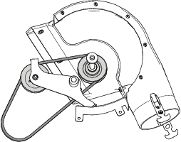
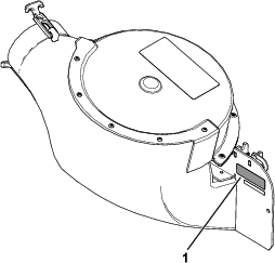
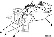
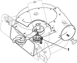
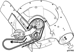
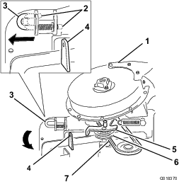
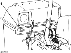
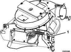
Whenever you need service, genuine Toro parts, or additional information, contact an Authorized Service Dealer or Toro Customer Service and have the model and serial numbers of your product ready. Figure 1 and Figure 2 or Figure 3 or identify the location of the model and serial numbers on the product. Write the numbers in the space provided.

g037983
g003368
g309299

This manual identifies potential hazards and has safety messages identified by the safety-alert symbol (Figure 4), which signals a hazard that may cause serious injury or death if you do not follow the recommended precautions.

g000502

This manual uses 2 words to highlight information. Important calls attention to special mechanical information and Note emphasizes general information worthy of special attention.

Warning

CALIFORNIA

Proposition 65 Warning

Use of this product may cause exposure to chemicals known to the State of California to cause cancer, birth defects, or other reproductive harm.

Safety

  • Become familiar with the safe operation of the equipment, with the operator controls, and safety signs.

  • Use extra care with grass catchers or other attachments. These can change the operating characteristics and the stability of the machine.

  • Follow the manufacturer's recommendations for adding or removing wheel weights or counterweights to improve stability.

  • Do not use a grass catcher on steep slopes. A heavy grass catcher could cause loss of control or overturn the machine.

  • Slow down and use extra care on hillsides. Be sure to travel in the recommended direction on hillsides. Turf conditions can affect the stability of the machine. Use extreme caution while operating near drop-offs.

  • Keep all movement on slopes slow and gradual. Do not make sudden changes in speed, direction, or turning.

  • The grass catcher can obstruct the view to the rear. Use extra care when operating in reverse.

  • Use care when loading or unloading the machine into a trailer or truck.

  • Never operate with the discharge deflector raised, removed or altered, unless using a grass catcher.

  • Keep hands and feet away from moving parts. Do not make adjustments with the engine running.

  • Park the machine on level ground, disengage the drives, and shut off the engine before leaving the operator's position for any reason including emptying the grass catcher or unclogging the chute.

  • If you remove the grass catcher, be sure to install any discharge deflector or guard that might have been removed to install the grass catcher. Do not operate the mower without either the entire grass catcher or the grass deflector in place.

  • Do not leave grass in the grass catcher for extended periods of time.

  • Grass catcher components are subject to wear, damage and deterioration, which could expose you to moving parts or allow objects to be thrown. Frequently check components and replace with the manufacturer's recommended parts, when necessary.

Towing Safety

  • Do not attach towed equipment except at the hitch point.

  • Follow the attachment manufacturer's recommendation for weight limits for towed equipment and towing on slopes.

  • Never allow children or others in or on towed equipment.

  • On slopes, the weight of the towed equipment may cause loss of traction and loss of control. Reduce towed weight and slow down.

  • Stopping distance increases with the weight of the towed load. Travel slowly and allow extra distance to stop.

  • Make wide turns to keep the attachment clear of the machine.

  • Do not tow a load that weighs more than the towing machine.

Safety and Instructional Decals

Graphic

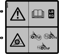
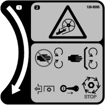
Safety decals and instructions are easily visible to the operator and are located near any area of potential danger. Replace any decal that is damaged or missing.

decal133-8061
decal126-4662
decal126-9451
decal126-4659
decal126-4853
decal106-5517
decal126-9595

Setup

Note: Determine the left and right sides of the machine from the normal operating position.

Preparing the Machine

  1. Park the machine on a level surface.

  2. Move the motion-control levers to the NEUTRAL-LOCK position.

  3. Engage the parking brake.

  4. Shut off the engine and remove the key.

g037289

Installing the ROPS Pin

Parts needed for this procedure:

ROPS-pin assembly2
Bolt (#10 x 3/4 inch)2
Washer (#10)2
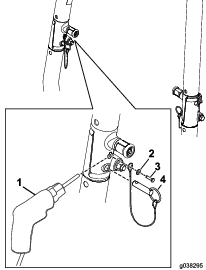
  1. Use a #18 (0.170 inch diameter) drill bit and drill out the lanyard hole in the ROPS (Figure 6).

    g038295
  2. Use the self-tapping screw (#10 x 3/4 inch) and washer to secure the ROPS-pin assembly to each side of the ROPS assembly (Figure 6).

  3. Insert the ROPS pin into the hole in the ROPS (Figure 6).

Installing the Weight Kit

Parts needed for this procedure:

Weight2
Channel plate2
Plate2
Tabbed plate2
Bolt (3/8 x 2-1/2 inches)4
Nut (3/8 inch)4
Flat weight2
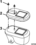
  1. Use the bolts (3/8 x 2-1/2 inches), nuts to secure the plates to the weight (Figure 7).

    g185955
  2. Add the flat weight to the weight assembly for a machine with a 122 cm (48 inches) mower deck (Figure 8).

    g037628
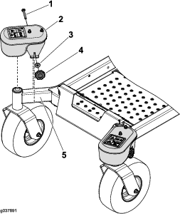
  3. Use the knob, washer, and carriage bolt (3/8 x 3-1/2 inch) to secure a caster weight to each caster arm (Figure 9).

    g037891

Installing the Bagger Support (If Applicable)

Parts needed for this procedure:

Left bagger support1
Right bagger support1
Left support bracket1
Right support bracket1
Bolt (5/16 x 3 inches)4
Bolt (3/8 x 1 inch)2
Flange nut (5/16 inch)4
Flange nut (3/8 inch)2
Washer6
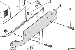
  1. Remove the bolts and nuts that secure the upper trim to the machine (Figure 10).

    Note: Do not perform this step on a 1500 Series machine.

    g037892
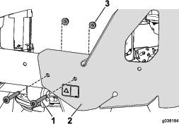
  2. Remove the bolts and nuts that secure the left side of the rear guard to the frame (Figure 11).

    Note: Perform the following steps on 1 side of the machine, then the other.

    g038184
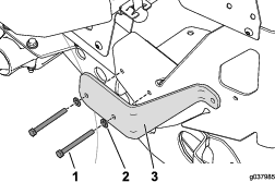
  3. Align the holes in the support bracket to the holes in the frame (Figure 12).

    g037985
  4. Insert the 2 bolts (5/16 x 3-1/4 inches) with washers into the holes(Figure 12).

    Note: Do not install the flange nuts at this time.

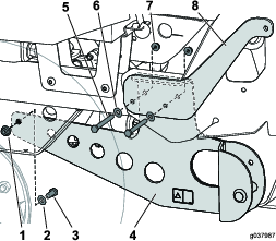
  5. Loosely install the bolt (1 inch), washer, and flange nut that secures the bagger mount to the transmission mount (Figure 13).

    g037987
  6. Align the holes in the bagger mount to the 2 bolts that you inserted earlier and secure it with the 2 flange nuts (Figure 13).

  7. Tighten all the hardware that you installed.

  8. Perform previous steps on the other side of the machine.

Installing the Bagger Brackets

Parts needed for this procedure:

Bagger bracket2
Bolt (3/8 x 1 inch)4
Washer4
Flange nut (3/8 inch)4
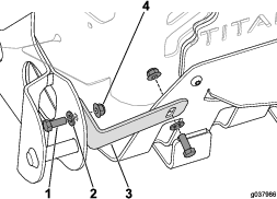
  1. Use the 2 bolts (3/8 x 1 inch), 2 washers, and 2 nuts to secure the bagger bracket to the machine (Figure 14).

    g037986
  2. Perform previous steps on the other side of the machine.

Installing the Transmission Support

Parts needed for this procedure:

Transmission support1
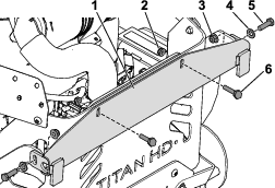
  1. Remove the 2 flange nuts from the support bolts on the left and right transmissions and set them aside (Figure 15).

    g189547
  2. Align the bracket to the support bolts and secure them with the 2 flange nuts you removed in the previous step (Figure 15).

Installing the Cross Brace

Parts needed for this procedure:

Cross brace1
Bolt (5/16 x 1-1/4 inches)2
Flange nut (5/16 inch)2
Washer (3/8 inch)2
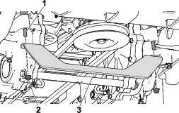
  1. Loosely install the 2 bolts (3/8 x 1-1/4 inches), washers, and flange nuts to hold the cross brace on the support bracket (Figure 16).

    g189869
  2. Loosely install the bolt (5/16 x 1-1/4 inches) and flange nut (5/16 inch) to hold the cross brace to the rear guard (Figure 16).

    Note: Leave the crossbar hardware loose until you align the bagger frame.

Installing the Bagger Frame

Parts needed for this procedure:

Bag support1
Lock-pin assembly2
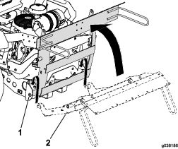
  1. Arrange the bagger frame around the pivot pins on the support bracket and rotate it forward (Figure 17).

    g038186
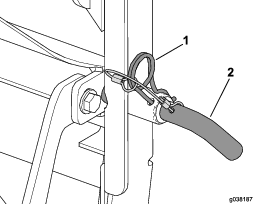
  2. Insert the lock pin through the bagger frame and cross brace (Figure 18).

    Note: You may need to loosen the hardware to align the lock pin to the hole.

    g038187
  3. Use the hairpin cotter to secure the lock pin (Figure 18).

  4. Tighten all loose hardware.

Installing the Bags

Parts needed for this procedure:

Bags2
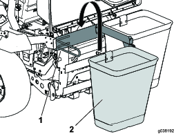
  1. Hook the bag to the bagger frame (Figure 19).

    g038192
  2. Close and latch the hood assembly.

Installing the Hitch Cover

Parts needed for this procedure:

Hitch cover1
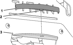
  1. Apply a lubricant to the nipple on the hitch cover.

  2. Align the hitch cover over the hitch and press it into place (Figure 20).

    g211241

Removing the Existing Belt Cover, Bracket, and Discharge Chute

Note: Clean the area around the belt cover before removing it.

  1. Lower the mower deck to the lowest height-of-cut position.

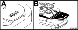
  2. Remove the right belt cover (Figure 21).

    g038092
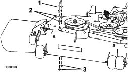
  3. Remove the right belt-cover bracket, 2 washers (60-inch mower deck only), and 2 flange nuts from the mower deck (Figure 22).

    Note: Retain the hardware that you removed during this procedure so that it is available for changeover.

    g038093
  4. Remove the locknut, bolt, spring, and spacer holding the deflector to the pivot brackets (Figure 23).

    g015594
  5. Remove the grass deflector (Figure 23).

Installing the Blower-Pulley Assembly and Belt-Cover Bracket

Parts needed for this procedure:

Blower-pulley assembly1
Belt-cover bracket1
Speed nut1
Carriage bolt (1/4 x 3/4 inch)2
Locknut (1/4 inch)2
Locknut (3/8 inch)3
Blower pulley1
Locknut (3/4 inch)1
Washer1
Pulley mount1
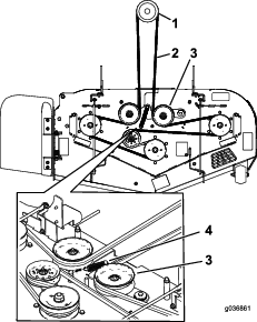
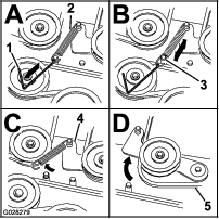
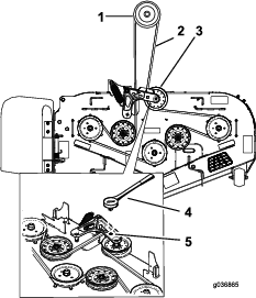
  1. On the machine, remove the spring tension from the spring-loaded idler pulley; refer to Figure 24 or Figure 26.

    Note: For 1500 and 2000 Series mower decks, use the spring-removal tool (Toro Part No. 92-5771) to remove the spring from the mower-deck post (Figure 25).

    Note: For 2500 Series mower decks, use a ratchet in the square hole in the idler arm to remove tension on the idler spring (Figure 26).

    g036861
    g028279
    g036865
  2. Remove the belt from the right mower-deck pulley.

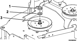
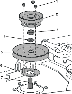
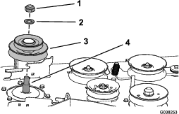
  3. Use a wrench (1-1/2 inches) to hold the spindle shaft, as you remove the locknut (3/4 inch) and washer from the spindle shaft (Figure 27).

    Note: Set aside the locknut (3/4 inch) and washer for blower 78436, 78437, 78438, 78404, 78405, and 78406.

    g038095
  4. Use a wrench (1-1/2 inches) to hold the spindle shaft, as you install the double pulley onto the right spindle shaft.

    • For blower Models 78433, 78434, 78435, 78401, 78402, and 78403, perform the following procedure:

      1. Use the locknut (3/4 inch) and washer to secure the new double pulley onto the right spindle shaft (Figure 28).

      2. Torque the locknut (3/4 inch) to 176 to 217 N∙m (130 to 160 ft-lb).

      g038253
    • For blower Models 78436, 78437, 78438, 78404, 78405, and 78406, perform the following procedure:

      1. Insert the threaded studs on pulley mount through the holes in the deck pulley (Figure 29).

      2. Use the locknut (3/4 inch) and washer that you set aside earlier to secure the deck pulley to the spindle shaft (Figure 29).

      3. Torque the locknut (3/4 inch) to 176 to 217 N∙m (130 to 160 ft-lb).

      4. Arrange the blower pulley onto the threaded studs and loosely install the locknut (Figure 29).

      5. Rotate the blower pulley clockwise until it stops.

      6. Torque the 3 locknuts to 18 N∙m (13 ft-lb).

      g188637
  5. Ensure that the blade bolt is torqued to 115 to 149 N∙m (85 to 110 ft-lb).

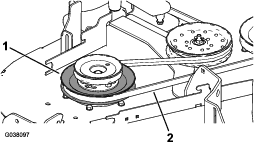
  6. Install the mower belt around the lower pulley of the double pulley (Figure 30).

    g038097
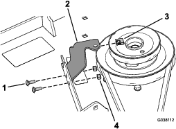
  7. Install the belt-cover bracket to the mower deck using 2 carriage bolts (1/4 x 3/4 inch) and 2 locknuts (1/4 inch) as shown in Figure 31.

  8. Install the speed nut onto the belt-cover bracket (Figure 31).

    g038112
  9. Install the mower deck belt around the spring-loaded idler pulley (Figure 24 or Figure 26).

  10. Use the spring-removal tool (Toro Part No. 92-5771) to attach the spring to the spring-loaded idler pulley.

Installing the Baffle

Parts needed for this procedure:

Baffle1
Carriage bolt (5/16 x 7/8 inch)1
Flange nut (5/16 inch)1
Carriage bolt (3/8 x 7/8 inch)2
Flange nut (3/8 inch)2
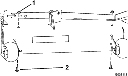
  1. Remove the 2 existing flange nuts (3/8 inch) and 2 carriage bolts (3/8 x 7/8 inch) from the mower deck (Figure 32).

    g038113
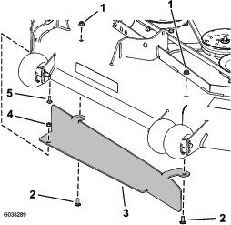
  2. Install the baffle using the carriage bolt (5/16 x 7/8 inch), flange nut (5/16 inch), 2 carriage bolts (3/8 x 7/8 inch), and 2 flange nuts (3/8 inch) as shown in Figure 33.

    g038289

Installing the Blower Assembly

Parts needed for this procedure:

Blower assembly1
Pivot pin1
Roll pin (3/16 x 7/8 inch)1

Blower Models 78433–78438

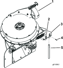
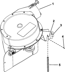
Verify that the pivot pin is secured on the blower assembly in the correct location (Figure 34).

  • If you have a 48-inch or 52-inch mower deck, install the pivot pin in the front hole (Figure 34).

  • If you have a 60-inch mower deck, install the pivot pin in the rear hole (Figure 34).

g018382
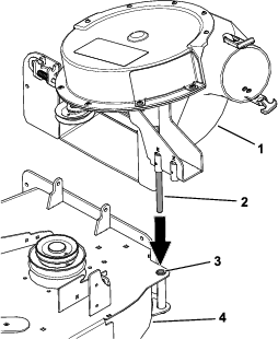
  1. Align the pivot pin on the blower with the pivot-pin hole in the mower deck (Figure 35).

    g038256
  2. Loosen or remove the guide pin (Figure 35).

    g189037
  3. Install the belt around the pulleys inside the blower (Figure 37).

    g037982
  4. Tighten or install the guide pin (Figure 37).

  5. Lower the blower and slide the pivot pin into the pivot hole (Figure 35).

    Note: Ensure that the belt remains positioned in the blower pulley.

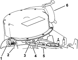
  6. Move the latch pin from the locking position to the open position (Figure 38).

    g018370
  7. Close the blower assembly and align the latch pin with the hole in the chute bracket (Figure 38).

  8. Move the latch pin to the locking position.

    Note: Ensure that the latch pin extends through the hole in the chute bracket.

    Note: Ensure that the latch firmly holds the blower assembly against the mower deck, but you can release it by hand.

Blower Models 78401–78406

Verify that the pivot pin is secured on the blower assembly in the correct location (Figure 39).

  • If you have a 48-inch or 52-inch mower deck, install the pivot pin in the front hole (Figure 39).

  • If you have a 60-inch mower deck, install the pivot pin in the rear hole (Figure 39).

g309297
  1. Align the pivot pin on the blower with the pivot-pin hole in the mower deck (Figure 40).

    g309295
  2. Install the belt around the pulleys inside the blower (Figure 41).

    g309298
  3. Lower the blower and slide the pivot pin into the pivot hole (Figure 40).

    Note: Ensure that the belt remains positioned in the blower pulley.

  4. Move the latch pin from the locking position to the open position (Figure 42).

    g309296
  5. Close the blower assembly and align the latch pin with the hole in the chute bracket (Figure 42).

  6. Move the latch pin to the locking position.

    Note: Ensure that the latch pin extends through the hole in the chute bracket.

    Note: Ensure that the latch firmly holds the blower assembly against the mower deck, but you can release it by hand.

Installing the Blower Belt, Spring, and Blower-Belt Cover

Parts needed for this procedure:

Blower-belt cover1
Cover knob1

Blower Models 78433–78438

  1. Arrange the blower belt around the drive pulley as shown in Figure 43.

    g218676
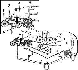
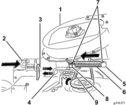
  2. Temporarily route the belt beneath the idler pulley (Figure 44).

    g018371
  3. Move the idler-pivot bracket toward the fixed spring post and install the spring by aligning the spring hook onto the idler-spring post (Figure 44).

    Note: Ensure that the spring hooks are positioned correctly on the spring posts.

  4. Pull the spring-loaded idler pulley away from the fixed spring post, and route the belt around the deck pulley (Figure 44).

    Note: Ensure that the belt is correctly routed around the blower pulley.

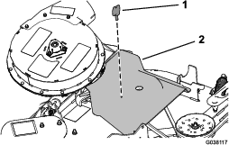
  5. Install the blower-belt cover over the blower belt and secure the blower-belt cover with the belt knob (Figure 45).

    g038117

Blower Models 78401–78406

  1. Pull back the spring-loaded idler pulley and route the blower belt around the drive pulley (Figure 46).

    g309586
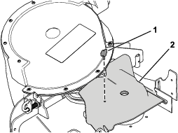
  2. Install the blower-belt cover over the blower belt and secure the blower-belt cover with the knob (Figure 47).

    g309587

Installing the Discharge Tubes

Parts needed for this procedure:

Upper tube1
Lower tube1
Bolt (#10 x 3/4 inch)3
Locknut (#10)3
Washer (7/32 inch)3
  1. Disengage the PTO and engage the parking brake.

  2. Shut off the engine, remove the key, and wait for all moving parts to stop before you leave the operating position.

  3. Lower the machine deck to the lowest height-of-cut position.

  4. Remove the bags for viewing the tube under the hood.

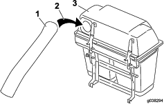
  5. Install the upper tube into the bagger opening and pull it back out so that the hopper seal is protruding out (Figure 48).

    g038294
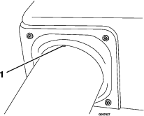
  6. Align the dimple in the upper tube equally between the screws securing the hopper seal to the hopper (Figure 49).

    Note: The hopper seal must protrude outward from the bagger hood.

    g007027
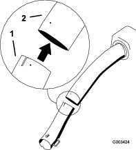
  7. Install the lower tube into the upper tube (Figure 50).

    g003424
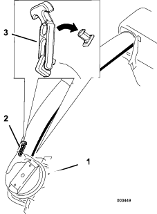
  8. Slide the lower tube onto the blower housing and latch them together (Figure 51).

    Note: There is a latch on the top and bottom of the blower housing.

    g003449
  9. Ensure that the machine deck is in the lowest height-of-cut position.

  10. Verify that the dimple from Figure 49 is still in place.

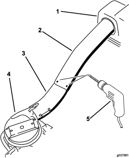
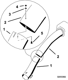
  11. Using the 3 holes or indentations in the upper tube as a template, and drill 3 holes (7/32 inch diameter) where the upper and lower tubes join together (Figure 52).

    g037981
  12. Remove the lower tube from the blower housing.

  13. Join the upper and lower tubes with 3 bolts (#10 x 3/4 inch), flat washers, and locknuts as shown in Figure 53.

    g003392
  14. Install the lower tube onto the blower housing and secure it with the latches.

Adjusting the Parking Brake

Check to ensure that the parking brake is adjusted properly. Refer to your Operator’s Manual for the correct procedure.

Checking the Tire Pressure

Increase the tire pressure due to the additional weight.

Note: This is not applicable with semi-pneumatic tires.

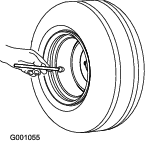
Check and increase the air pressure in the front caster wheels and rear tires (Figure 54).

Air pressure in the rear tires: 138 kPa (20 psi)

Air pressure in the front caster wheels: 172 kPa (25 psi)

g001055

Operation

Note: Determine the left and right sides of the machine from the normal operating position.

Warning

To avoid personal injury, follow these procedures:

  • Become familiar with all operating and safety instructions in the Operator's Manual for the mower before using this attachment.

  • Never remove the discharge tube, bags, bagger top, or the chute while the engine is running.

  • Always shut the engine off and wait for all moving parts to stop before clearing an obstruction from the bagging system.

  • Never do maintenance or repairs while the engine is running.

Warning

Without the grass deflector, bagger tubes or complete bagger assembly mounted in place, you and others are exposed to blade contact and thrown debris. Contact with the rotating mower blade(s) and thrown debris will cause injury or death.

  • Always install the grass deflector when removing the bagger and changing to side discharge mode.

  • If the grass deflector is ever damaged, replace it immediately. The grass deflector routes material down toward the turf.

  • Never put your hands or feet under the mower.

  • Never try to clear the discharge area or mower blades unless you move the power take off (PTO) to off and rotate the ignition key to off. Also remove the key and pull the wire off of the spark plug(s).

  • Turn off the engine before unclogging the discharge chute.

Emptying the Grass Bags

Warning

Debris, such as leaves, grass, or brush can catch fire. A fire in the engine area can cause personal injury and property damage.

  • Keep the engine and muffler area free of debris accumulation.

  • Take care when opening the bagger cover to keep debris from falling onto the engine and muffler area.

  • Allow the machine to cool before storing it.

Grass bags are heavy when full. Be careful when lifting or handling a grass bag that is full.

  1. Park the machine on a level surface and disengage the blade control switch.

  2. Move the motion control levers outward to the neutral lock position, shut off the engine, remove the key, set the parking brake and wait for all moving parts to stop before leaving the operating position.

  3. Unlatch the bagger latch.

  4. Open the bagger hood.

  5. Compress the debris into the bags. With both hands, lift up on the bag and unhook it from the bagger bracket.

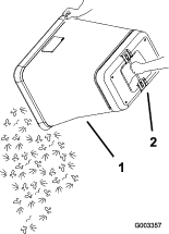
  6. Grab the handle on the bottom of the bag and tip it over to empty the bag (Figure 55).

    g003357
  7. Install the bag tab into the notch in the bagger support frame.

  8. Lower the bagger hood over the bags.

  9. Latch the bagger hood.

Clearing Obstructions from the Bagger System

Warning

When the bagger is in operation, the blower is rotating and can cut off or injure hands and fingers.

  • Before adjusting, cleaning, repairing, and inspecting the blower, and before unclogging the chute, shut off the engine, wait for all moving parts to stop, and remove the key.

  • Ensure that the rotation indicator stops.

  • Use a stick, not your hands, to remove an obstruction from the blower and tube.

  • Keep your hands and feet away from moving parts. Do not make adjustments with the engine running.

  1. Disengage the PTO and engage the parking brake.

  2. Shut off the engine, remove the key, and wait for all moving parts to stop before leaving the operating position.

  3. Empty the bags.

  4. Unlatch the lower tube.

  5. Remove the tubes from the bagger.

  6. Use a stick or similar object to remove and clear the obstruction from the tube assembly.

    Note: In most cases, the debris can be shaken out of the tubes.

  7. If the blower assembly is plugged, unlatch the bagger blower assembly, remove the belt, and swing it open.

  8. Use a stick or similar object, not your hands, to remove and clear the obstruction from the blower assembly.

  9. Completely install the bagger system before you resume mowing.

Removing the Bagger

Warning

Components around the engine are hot if the machine has been running. Touching hot components can cause burns.

  • Do not touch the engine hot components.

  • Allow engine to cool before removing the bagger.

  1. Disengage the PTO.

  2. Shut off the engine, engage the parking brake, remove the key, and wait for all moving parts to stop before leaving the operating position.

  3. Unlatch the lower tube from the blower and remove the tube from the blower assembly.

  4. Remove the tube from the bagger hood.

  5. Lower the mower deck to the lowest height-of-cut position.

  6. Remove the knob that secures the belt cover to the mower deck.

  7. Remove the blower belt from the mower-pulley assembly.

  8. Open the blower assembly.

  9. Remove the blower assembly from the pivot hole.

  10. If you are changing to side discharge mode, ensure that the grass deflector is installed and can be lowered into working position.

  11. Remove the hood and bag assembly.

Transporting the Machine

Do not leave grass or debris in the bagger while transporting the machine.

Danger

Transporting the machine with grass or debris in the bagger can damage the machine.

Do not leave grass or debris in the bagger while transporting the machine.

Operating Tips

Tips for Bagging

Remembering the Size

Remember that the machine is longer and wider with this attachment installed. By turning too sharply in confined places you may damage the attachment.

Trimming

Always trim with the left side of the mower. Do not trim with the right side of the mower because you could damage the bagger chute and discharge tube.

Cutting Height

Do not set the mower cutting height too low because long grass surrounding the mower can prevent air from getting under the mower and entering the bagging system. If not enough air gets under the mower, the bagging system will plug.

Cutting Frequency

Cut the grass often, especially when it grows rapidly. You will have to cut your grass twice if it gets excessively long.

Cutting Technique

For best lawn appearance, be sure to slightly overlap the mower into the previously cut area. This helps reduce the load on the engine and reduces the chance of plugging the chute and discharge tube.

Bagging Speed

Most often, you will bag with the mower throttle in the FAST position and drive at a normal ground speed. However, in extremely dry and dusty grass, you may want to slightly reduce the throttle speed and increase the ground speed of the mower. The bagging system may plug if you drive too fast and the engine speed gets too slow. On hills, it may be necessary to slow the mower ground speed. This helps maintain the engine speed and bagging efficiency. Mow downhill whenever possible.

Caution

As the bagger fills, extra weight is added to the back of the machine. If you stop and start the machine suddenly on hills, you may lose steering control or the machine may tip.

  • Do not start or stop suddenly when going uphill or downhill. Avoid uphill starts.

  • If you do stop the machine when going uphill, disengage the blade control. Then back down the hill using a slow speed.

  • Avoid sudden turns or rapid speed changes on slopes.

  • Never operate the machine without the bagger attachment and the front weights still installed.

Bagging Long Grass

Excessively long grass is heavy and may not be propelled completely into the grass bags. If this happens, the discharge tube and chute may plug. To avoid plugging the bagging system, mow the grass at a high height of cut, then lower the mower to your normal cutting height and repeat the bagging process.

Bagging Wet Grass

Always try to cut grass when it is dry because your lawn will have a neat appearance. If you must cut wet grass, use the conventional side discharge feature of the mower. Several hours later, when the clippings are dry, install the complete bagger attachment and vacuum up the grass clippings.

Signs of Plugging

As you are bagging, a small amount of grass clippings normally blow out the front of the mower. An excessive amount of clippings blowing out indicates that the bags are full or the system is plugged.

Maintenance

Note: Determine the left and right sides of the machine from the normal operating position.

Recommended Maintenance Schedule(s)

Maintenance Service IntervalMaintenance Procedure
After the first 8 hours
  • Inspect the blower belt.
  • Inspect the bagger.
  • After the first 10 hours
  • Inspect the bagger
  • Before each use or daily
  • Clean the hood screen.
  • Clean the bagger.
  • Every 25 hours
  • Inspect the blower belt.
  • Every 50 hours
  • Grease the idler arm (blower models 78433–78438 only).
  • Every 100 hours
  • Inspect the bagger.
  • Before storage
  • Inspect the bagger
  • Warning

    If you leave the key in the ignition switch, someone could accidently start the engine and seriously injure you or other bystanders.

    Remove the key from the ignition and disconnect the wire from the spark plug before you do any maintenance. Set the wire aside so that it does not accidentally contact the spark plug.

    Warning

    Engines can become hot when they are operating. Burns can occur from contacting hot surfaces.

    Allow engines, especially the muffler, to cool before touching.

    Warning

    Debris, such as leaves, grass, or brush can catch fire. A fire in the engine area can cause personal injury and property damage.

    • Keep the engine and muffler area free of debris accumulation.

    • Take care when opening the bagger cover to keep debris from falling onto the engine and muffler area.

    • Allow the machine to cool before storing it.

    Cleaning the Hood Screen

    Maintenance Service IntervalMaintenance Procedure
    Before each use or daily
  • Clean the hood screen.
  • The screens need to be cleaned before each use.

    1. Park the machine on a level surface.

    2. Disengage the blade-control switch, engage the parking brake, and move the motion-control levers outward to the NEUTRAL-LOCK position.

    3. Shut off the engine and remove the key.

    4. Open the bagger hood.

    5. Clean the debris from the screen.

    6. Close the bagger hood.

    Inspecting the Bagger Attachment

    Maintenance Service IntervalMaintenance Procedure
    After the first 10 hours
  • Inspect the bagger
  • Before storage
  • Inspect the bagger
  • Inspect the bagger attachment after the first 10 hours of operation, and monthly thereafter.

    1. Check the chute, discharge tube, and the bagger top. Replace these parts if they are cracked or broken.

    2. Tighten all nuts, bolts, and screws.

    3. Inspect all fasteners and latches; replace any missing or damaged.

    4. Inspect the grass bags for deterioration.

      Warning

      You or bystanders could be severely injured by flying debris or thrown objects that may pass through torn, worn, or deteriorated grass bags.

      • Check the grass bags for holes, rips, wear, and other deterioration.

      • Do not wash the grass bags.

      • If the bag has deteriorated, install new grass bags supplied by the manufacturer of this bagger attachment.

    Cleaning the Bagger and Bags

    Maintenance Service IntervalMaintenance Procedure
    Before each use or daily
  • Clean the bagger.
  • The bagger needs to be cleaned daily.

    1. Wash the inside and outside of the bagger hood, bags, tube, and the underside of the mower deck. Use a mild automotive detergent to remove dirt.

    2. Ensure that you remove matted grass from all parts.

    3. After washing all the parts, let them dry thoroughly.

    Note: With all parts installed, start and run the machine for approximately 1 minute to assist in drying.

    Inspecting the Blower Belt

    Maintenance Service IntervalMaintenance Procedure
    After the first 8 hours
  • Inspect the blower belt.
  • Every 25 hours
  • Inspect the blower belt.
  • Check belts for cracks, frayed edges, burn marks, or any other damage. Replace any belts that are damaged.

    Replacing the Blower Belt

    Blower Models 78433–78438

    1. Disengage the PTO, move the motion-control levers to the NEUTRAL-LOCK position, and engage the parking brake.

    2. Shut off the engine, remove the key, and wait for all moving parts to stop before leaving the operating position.

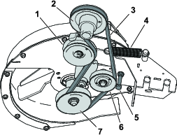
    3. Loosen or remove belt guide (Figure 56).

    4. Pull back on the spring-loaded idler pulley to relieve the belt tension (Figure 56).
      g189890
    5. Remove the existing blower belt.

    6. Install the new belt around the blower pulley (Figure 56).

    7. Tighten or install the belt guide (Figure 56).

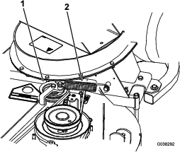
    8. Install the spring as shown in Figure 57.
      g038292
    9. Install the belt onto the spring-loaded idler pulley (Figure 57).

    Blower Models 78401–78406

    1. Park the machine on a level surface.

    2. Disengage the blade-control switch, engage the parking brake, and move the motion-control levers outward to the NEUTRAL-LOCK position.

    3. Shut off the engine and remove the key.

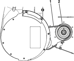
    4. Pull back on the spring-loaded idler pulley to relieve the belt tension.

    5. Remove the existing blower belt (Figure and Figure ).
      g309586
      g309298
    6. Install the new belt around the blower pulley; refer to Installing the Blower Belt, Spring, and Blower-Belt Cover.

    Greasing the Idler Arm for Blower Models 78433–78438

    Maintenance Service IntervalMaintenance Procedure
    Every 50 hours
  • Grease the idler arm (blower models 78433–78438 only).
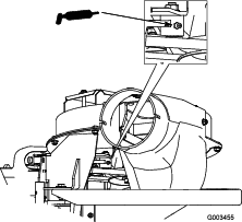
  • Grease the bagger belt idler arm (Figure 60) every 50 hours.
    g003455

    Inspecting the Bagger

    Maintenance Service IntervalMaintenance Procedure
    After the first 8 hours
  • Inspect the bagger.
  • Every 100 hours
  • Inspect the bagger.
    1. Disengage the PTO, move the motion-control levers to the NEUTRAL-LOCK position, and engeage the parking brake.

    2. Shut off the engine, remove the key, and wait for all moving parts to stop before leaving the operating position.

    3. Check the upper tube, lower tube, bagger hood, and the blower assembly. Replace these parts if they are cracked or broken.

    4. Check the bags, bagger frame, and screen. Replace any parts that are cracked or broken.

    5. Tighten all nuts, bolts, and screws.

    Inspecting the Mower Blades

    1. Inspect the mower blades regularly and whenever a blade strikes a foreign object.

    2. If blades are badly worn or damaged, install new blades. Refer to your machine Operator's Manual for complete blade maintenance.

    Selecting the Mower Blades

    In most mowing conditions, the standard high lift blades provide the best bagging performance.

    The Toro Atomic blade is recommended for bagging leaves in dry conditions. In dry dusty conditions, the medium lift or low lift blades reduce dust and dirt blowout while providing effective bagging air flow.

    Contact an Authorized Service Dealer for the proper blades for different mowing conditions.

    Refer to the machines Operator's Manual for more information on installing blades.

    Replacing the Grass Deflector

    Warning

    An uncovered discharge opening could allow the machine to throw objects toward you or bystanders, resulting in serious injury. Also, contact with the blade could occur.

    • Never operate the machine without a grass deflector, a mulch plate, or a bagger system installed.

    • Ensure that the grass deflector is in the down position.

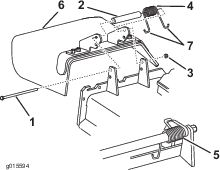
    1. Place one end of the spring behind the deck edge and the other end on the grass deflector (Figure 61).
      g015594
    2. Use the bolt and nut to secure the grass deflector assembly to the mower deck (Figure 61).

    3. Place the J-hook end of the spring around the grass deflector (Figure 61).

    Important: The grass deflector must be able to lower down into position. Lift the deflector up to test that it lowers into the full-down position.
    Storage

    1. Empty the bagger attachment; refer to Emptying the Grass Bags.

    2. Inspect the bagger attachment for damage.

    3. Ensure that the bags are empty and thoroughly dry.

    4. Inspect the belt for wear or cracks; refer to Inspecting the Blower Belt.

    5. Store the machine in a clean, dry place, out of direct sunlight. If you must store the machine outside, cover it with a weatherproof cover. This protects the plastic parts and extends the life of the machine.

    Troubleshooting

    ProblemPossible CauseCorrective Action
    There is abnormal vibration.
    1. The cutting blade(s) is/are bent or unbalanced.
    2. The blade mounting bolt is loose.
    3. The blower pulley or pulley assembly is loose.
    4. The blower belt is worn.
    5. The blower fan blade(s) is/are bent or unbalanced.
    1. Install new cutting blade(s).
    2. Tighten the blade mounting bolt.
    3. Tighten the appropriate pulley.
    4. Replace the belt.
    5. Contact an Authorized Service Dealer.
    There is reduced bagging performance.
    1. The engine speed is low.
    2. The bagger-hood screen is plugged.
    3. The blower belt is loose.
    4. The blower or tube is plugged.
    5. The bags are full.
    1. Always operate the bagger at full throttle.
    2. Remove the debris, leaves or grass clippings from the screen.
    3. Replace the bagger belt.
    4. Locate and remove the plugged debris.
    5. Empty the bags.
    The blower and tubes plug too frequently.
    1. The engine speed is low.
    2. The grass is too wet.
    3. The grass is too long.
    4. The screen in the hood is plugged.
    5. The ground speed is too fast.
    6. The bagger belt is worn.
    1. Always operate the bagger at full throttle.
    2. Cut the grass when it is dry.
    3. Do not cut more than 51 to 76 mm (2 to 3 inches) or 1/3 of the grass height, which ever is less.
    4. Remove the debris, leaves, or grass clippings from the screen.
    5. Drive slower at full throttle.
    6. Replace the belt.
    There is debris blowout.
    1. The bags are full.
    2. The ground speed is too fast.
    3. The mower deck is not leveled.
    1. Dump the bags more frequently.
    2. Drive slower at full throttle.
    3. See the mower Operator's Manual for leveling the mower deck.
    The blower impeller does not spin freely.
    1. The blower is plugged.
    2. The impeller is not aligned.
    1. Remove the debris, leaves, or grass clippings from the blower impeller.
    2. Contact an Authorized Service Dealer.