Introduction

The GeoLink® Precision Spray System automatically controls the spray application rate and the spraying area. The system monitors the area sprayed, the speed of the vehicle, and the total volume of material sprayed. You set the target volume per unit area to spray and the spray system automatically maintains the flow within the proper range of the vehicle speed and continually displays the actual volume of material per area sprayed.

Read this manual carefully to learn how to operate and maintain your product properly. The information in this manual can help you and others avoid injury and product damage. Although Toro designs and produces safe products, you are responsible for operating the product properly and safely. You may contact Toro directly at www.Toro.com for product and accessory information, help finding a dealer, or to register your product.

Whenever you need service, genuine Toro parts, or additional information, contact an Authorized Service Dealer or Toro Customer Service and have the model and serial numbers of your product ready.

This manual identifies potential hazards and has safety messages identified by the safety-alert symbol (Figure 1), which signals a hazard that may cause serious injury or death if you do not follow the recommended precautions.

g000502

This manual uses 2 words to highlight information. Important calls attention to special mechanical information and Note emphasizes general information worthy of special attention.

Warning

CALIFORNIA

Proposition 65 Warning

Use of this product may cause exposure to chemicals known to the State of California to cause cancer, birth defects, or other reproductive harm.

Safety

Read and understand the contents of this Operator’s Manual before operating the console computer.

  • Keep these instructions with the Operator’s Manual for the turf sprayer.

  • It is very important that all who operate this equipment have ready access to these instructions at all times.

  • Read these instructions and the instructions in the Operator’s Manual for the turf sprayer carefully. Be familiar with the controls and the proper use of the equipment.

  • Never allow children or people unfamiliar with these instructions to use the controls.

  • Never spray while people, especially children, or pets are nearby.

  • Chemicals can injure people, animals, plants, soils, or other property. To avoid personal injury and environmental damage:

    • Select the proper chemicals for the job.

    • Follow the manufacturer’s instructions on the chemical container labels. Apply and handle chemicals as recommended.

    • Handle and apply the chemicals with care.

    • Wear all necessary protective equipment.

    • Handle chemicals in well-ventilated areas.

    • Never smoke when handling chemicals.

    • Properly dispose of unused chemicals and containers.

  • Keep in mind that the operator or user is responsible for accidents or hazards occurring to other people or for damage to property.

Product Overview

g204997
g204996
g204995
g205645
g205646

Become familiar with the controls before you start the engine and operate the sprayer.

Floating-Menu Bar

g203292

Using the Floating Menu-Bar

Accessing the Floating-Menu Bar

Swipe upward from the bottom of the display to access the floating-menu bar (Figure 8).

g203365

Power Down Icon

Use the POWER DOWN icon to shut off the GeoLink system (Figure 7).

Note: During normal operation, the X25 spray system powers ON when the key switch is in the RUN position; the X25 spray system powers OFF when the key switch is in the SHUT OFF position.

Help icon

Press the HELP ICON on the floating-menu bar to display the individual help icons that describe the controls on the current screen (Figure 7). Pushing the individual help icon displays the descriptive text for that control (Figure 9). Press the help icon on the floating-menu bar again to clear the individual help icons.

g203343

USB Eject Icon

Press the USB EJECT icon before you remove a USB device from the X25 control console (Figure 7). The USB eject icon is available on the floating-menu bar only when you have a USB storage device inserted into the USB port.

Note: The USB port (not shown) is located at the back of the monitor.

Screenshot Icon

Press the SCREENSHOT icon to record the current screen image onto the USB storage device.

Manage Global-Home Screens Icon

Press the MANAGE GLOBAL-HOME SCREENS icon to save the layout of the operation screen. Use the manage global-home screen to reduce the clutter of the operation screen or quickly return to display the required information in the operation screen. Display or hide the required views in the operation screen and press the SAVE HOME SCREEN icon to save the layout.

Screen Brightness Icons

Use the SCREEN BRIGHTNESS icons (Figure 7) to adjust the screen brightness of the control console:

  • Press the (-) screen brightness icon to reduce display brightness.

  • Press the (+) screen brightness icon to increase display brightness.

  • Press the brightness mode icon to select 1 of the following:

    • Auto (uses the light sensor in the control console to adjust the screen brightness)

    • Day mode (preset screen brightness for machine operation during bright ambient light)

    • Night mode (preset screen brightness for machine operation during low ambient light)

Power Button

Important: The system powers ON when you start the machine. The power button is not needed to start the system.

  • During normal operation, power ON the X25 spray system with the key switch in the RUN position.

    Note: When necessary, you can power ON the X25 spray system by pushing the power button at the back of the control console (Figure 10).

  • Power OFF the X25 spray system with the key switch in the SHUT OFF position.

    Note: In an emergency, you can press the power button at the back of the control console (Figure 10) to shut off the X25 spray system.

Note: Turning off the console correctly does not affect the data stored in the ECU memory.

g203113

Cancel and Confirm Buttons

Use these buttons to cancel or confirm an entry or a selection. You must select 1 of these buttons to progress from any screen displaying them (Figure 11).

g030695

Implement Color Indicators

These indicators show the position and direction of the vehicle and its implement.

The implement color indicates the status of the product application as follows (Figure 12):

  • Red—the boom section is off.

  • Blue—the boom section is inhibited (on and not flowing, typically due to low speed or pressure).

  • Yellow—the boom section is on and not flowing intentionally (typically due to auto-section control stopping the flow).

  • Green—the boom section is on and flowing.

    g031203

The following are important acronyms for the user to understand:

  • WAAS (Wide Area Augmentation System)—This positioning-correction system was developed by the US Federal Aviation Administration to serve as an air navigation aid by improving the accuracy and availability of the GPS signals.

  • RTK (Real Time Kinematic)— RTK Network - a group of land-base stations that transmit position data to a server through the internet. GPS guided machines equipped with RTK correction exchange data with the server, transmitting position information and receiving correction information through cellular data exchanges. The server uses the position data from the base station to calculate position-correction data and transmits it to the vehicles through the cellular modem. The corrected GPS position provides location accuracy between 1 to 2 cm (0.39 to 0.79 inch) in real time.

  • GLONASS (Global Navigation Satellite System (Russian GNSS))—This allows the GPS receiver to use the Russian satellite navigation system in addition to GPS.

Operation

The computer in the automatic section controller (ASC) controls the spray application rate for varying vehicle speeds. You set the target volume per unit area to spray, and the ASC automatically maintains the flow within the proper range of the vehicle speed and continually displays the actual volume of material per area sprayed. The X25 control console also monitors the area sprayed, the speed of the vehicle, and the total volume of material sprayed.

You can configure global positioning system options for the GeoLink system 2 ways:

  • Set the GPS to use the WAAS with the RTK correction (GPS signal with position and location correction data transmitted through a cellular modem).

  • Set the GPS to use the WAAS only (GPS with no correction data) for location and guidance.

Setting the GeoLink system to use the WAAS with RTK correction increases the positioning accuracy of the GeoLink spray system and enables additional capabilities with the X25 control console.

Note: Ensure that the sprayer is calibrated correctly before starting to spray.

Note: Ensure that the InfoCenter is set to GeoLink before using the display to spray.

Understanding the Different Display Modes

The availability of the sprayer controls, options, and settings depend upon which display mode you are using. The display mode is controlled through the user access level menu on the settings screen.

  • Easy Mode—This mode is intended for general spraying that all operators can use.

  • Standard Mode—This mode is intended for job setup, field boundary creation, calibration and general spraying. You can password protect the standard mode and use this mode for setting up extra features of the GeoLink system. The standard mode information is in video format. Please refer to the videos on the USB drive that came with the GeoLink system or on www.Toro.com.

    Note: Use the standard mode when you map a spray boundary.

  • Expert Mode—This mode is intended for the distributor to use when diagnosing and troubleshooting system issues. The expert mode is password protected and allows the distributor to help with customer service.

g204034

Starting the X25 Command Console

  1. Ensure that the GeoLink components and finish kit are installed.

  2. Start the machine and wait a few seconds for the command console to start.

    Note: Remember the following about starting and shutting off the command console:

    • Shut off the machine to power OFF the command console and X25 spray system.

    • Use the power down icon on the floating-menu bar to shut off the display only.

    • The green button at the back of the command console turns the power on or off console.

    • Shutting off the command console does not affect the data stored in the computer.

Using the Touch Screen

You access, add, or modify sprayer information on the X25 control console by touching the screen and working with the individual icons.

  • Press any icon on the screen to display what is shown on the screen.

  • Additional options display when you press a particular icon.

  • Select options as required.

  • Confirm the new display (Figure 11).

Selecting a Language and Accepting the License Agreement

The screen that follows the splash screen displays the language selection and the EULA (end user license agreement).

  1. If needed, press the languages icon to change the X25 display to a different language (Figure 14).

    Note: Setting the language in the EULA screen changes the language setting throughout the X25 user interface. You can also change the language in the User settings.

    g203216
  2. At the language selection dialogue box, navigate to your preferred language, select it from the list, and press the Yes icon (Figure 15).

    The X25 control console starts in the selected language.

    g203217
  3. Read the EULA (Figure 14).

    Use the scroll bar to navigate to the bottom of the screen. The Yes icon will change to green (Figure 14).

  4. Press the YES icon to move to the home screen (Figure 14).

Using the Master Switch on the X25 Control Console

g203807

The master switch icon indicates the readiness (Figure 16) of the system by the following colors:

  • Green—indicates that the system is ready and the sprayer controller is on and working.

  • White—sprayer controller is in standby.

  • Red—indicates that the system is not ready and the sprayer controller is off and cannot be used.

When the master switch icon is red, press the icon to display the master switch status, which shows the number of active alarms (Figure 17).

g205202

At any time, press the confirm icon (Figure 17) to return to the main screen and complete the necessary corrective action.

Using the Master Switch

Multi Pro 1750 Turf Sprayer

The master switch on the home screen indicates the sprayer system is on or off (Figure 16).

Using the Master Switch

Multi Pro 5800 Turf Sprayer

The master switch on the home screen turns the sprayer system on or off (Figure 16). This switch does not work if the master-section switch (foot switch) or the left, center, and right section switches of the machine are in the OFF position; refer to the Operator’s Manual for information about the master-section switch and the 3 section switches.

  • Press the master-switch icon to run the sprayer system (the icon turns green).

  • Press the master-switch icon to shut off the sprayer system (the icon turns white).

Selecting the Correct Units of Measure

The following options are available: Metric, Imperial (US), and Imperial (UK). The United States (US) and the United Kingdom (UK) imperial options are provided because gallons and fluid ounces have different measurements in the US and the UK.

  1. Press the setup icon on the main screen (Figure 18).

    g204035
  2. Press the user icon (Figure 19).

    g203793
  3. Press the region icon (Figure 19).

  4. Press the units icon (Figure 19).

  5. As needed, select the correct units and application rate, and press the confirm icon (Figure 20).

    g204046

Using the Easy Mode

Use the easy mode for spraying areas with defined boundaries, allowing you to select from the list of jobs and display the spraying area.

g203493

Using the Different Spraying Methods

Automatic Section Control (ASC) Icon

SettingDescription
ASC ONGeoLink controls the operation of the individual nozzle sections.
ASC OFFThe operator controls the nozzle sections as groups with the left, center, and right spray-section switches.
ASC INHIBITED (MANUAL MODE)The operator controls the nozzle sections as groups with the left, center, and right spray-section switches.

Boundary Limit Icon

SettingDescription
FIELD BOUNDARYGeoLink turns on nozzle sections as the turf sprayer enters the boundary of a work region that you defined for a spraying job.
GeoLink turns off nozzle sections as the turf sprayer enters excluded regions within the work region.
GeoLink turns off nozzle sections as the turf sprayer exits the boundary of a work region.
GeoLink turns off nozzle sections where pass-to-pass spraying overlaps.
UNLIMITEDGeoLink does not control nozzle sections within the boundary of a work region or excluded regions within the work region.
GeoLink turns off nozzle sections where pass-to-pass spraying overlaps.
Field Boundary disabledThe operator of the turf sprayer manually turns the left, center, and right spray section on or off.
GeoLink provides no control of nozzle sections.
GeoLink provides no control of pass-to-pass spraying overlaps.

Rate Control Icon

SettingDescription
Automatic (Auto)GeoLink controls the application rate based on the rate that you set for the active spray job or the rate you set in the sprayer control panel.
ManualYou control the application rate while you spray.

Spraying with a Field Boundary

This method allows you to spray or excludes you from spraying a job region defined by a boundary: within defined boundaries that are setup. You create the boundaries through the display in Standard Mode.

The field boundary spraying method allows the following:

  • The GeoLink system controls the nozzle sections within a field boundary and with pass-to-pass control.

  • The GeoLink system controls the application rate.

  1. Select the auto-selection control-configuration icon (ASC icon) and the sprayer-controller icon to open these screens (Figure 22).

  2. Select the ASC icon to the ON position, select the boundary limit to the FIELD BOUNDARY position, and select the rate control to the AUTO position (Figure 22).

    g209112

Spraying with an Unlimited Boundary

This method allows you to spray any area and has no boundaries.

This spraying method allows the following:

  • The GeoLink system controls the nozzle sections with pass to pass control without any field boundary.

  • The GeoLink system controls the application rate.

  1. Select the auto-selection control-configuration icon and the sprayer-controller icon (Figure 23).

  2. Select the ASC icon to the ON position, select the boundary limit to the UNLIMITED position, and select the rate control to the AUTO position (Figure 23).

    g209115

Spraying with Rate Control Only

This spraying method allows the following:

  • The operator controls the boom sections.

  • The GeoLink system controls the application rate.

  1. Select the auto-selection control-configuration icon and the sprayer-controller icon (Figure 24).

  2. Select the ASC icon to the OFF position, and select the rate control to the AUTO position (Figure 24).

    g209114

Spraying Manually

This spraying method allows the following:

  • The operator controls the boom sections.

  • The operator controls the application rate.

  1. Select the auto-selection control-configuration icon and the sprayer-controller icon (Figure 25).

  2. Select the rate control to the MANUAL position (Figure 25).

    Note: ASC turns to ASC Inhibited (Manual Mode)

    g209113

Creating a New Product Entry and Setting the Tank Volume

Note: Ensure that the units are correct for your use. Refer to Selecting the Correct Units of Measure in the Operator’s Manual.

Creating a New Product Entry

  1. Fill the tank with water.

  2. Press the sprayer-controller icon and expand the sprayer-controller panel (Figure 26).

    g204096
  3. Press the ECU 1 icon (Figure 26).

  4. Press the PRODUCT CONFIGURATION icon (Figure 26).

    The product configuration dialog box opens.

  5. In the product configuration window, press the PRODUCT SELECTION LIST icon (Figure 27).

    g204127
  6. Press the NEW PRODUCT... icon, and press the confirm icon (Figure 27).

    The New Product Setup wizard displays.

  7. On step 1 of the new product setup dialog box, press the icon, and press the next icon (Figure 28).

    g204240
  8. Press the PRODUCT NAME icon, enter the product name with the display keyboard, and press the confirm icon (Figure 29).

    g204241
  9. On step 2 of the new product setup dialog box, press the NEXT icon (Figure 30).

    g204328
  10. On step 3 of the new product setup dialog box, set the default product application rates as follows:

    g205035
    • Set a rate that you raise or lower application preset rates 1 and 2 by pressing the PRODUCT RATE INCREMENT icon (Figure 32).

      g204244
      1. Use the numeric pad of the display to enter the increment rate for the 2 preset application rates (Figure 33).

        g204317
      2. Press the confirm icon (Figure 33).

    • Press the PRODUCT RATE PRESET 1 or PRODUCT RATE PRESET 2 icons to set the preset product application rates as follows: (Figure 32).

      1. Use the numeric pad of the display to enter the preset application rate (Figure 33).

        g205038
      2. Press the confirm icon (Figure 33).

  11. On step 4 of the new product setup dialog box, confirm icon (Figure 35).

    g204329
  12. In the product configuration window, press the confirm icon to save the new product information (Figure 35).

Entering Product Tank Volume

  1. Press the TANK FILL icon (Figure 39).

    g204246
  2. Press the VOLUME icon (Figure 36).

  3. Use the numeric pad of the display to enter 1 of the following:

    Note: Press the INCREMENT VALUE or DECREMENT VALUE icons to enter a preset increment of product volume quantity.

    g204276
    • If you are entering a final product volume into the tank (such as water and chemicals), enter the total volume of product that you will add product to the tank, press the confirm icon, and press the confirm icon on the tank fill window (Figure 38).

      Note: The volume of water and product is less than or equal to the configured tank capacity.

      g204242
    • If you are incrementally adding chemicals to water, enter the volume of water in the tank , press the confirm icon, and proceed to step 4.

      Note: The volume of water and product is less than or equal to the configured tank capacity.

  4. If you are incrementally adding chemicals to water, press the VOLUME INCREMENTS icon (Figure 40).

    g204245
  5. Use the numeric pad of the display to enter increment of the volume of product (such as chemicals to water) that you will add product to the tank, and press the confirm icon (Figure 40).

    Example: 19 L (5 gallon), 114 L (30 gallon), or 208 L (55 gallon) increments.

  6. If you are incrementally adding chemicals to water, add the product into the tank and press the INCREMENT AMOUNT OF PRODUCT icon (Figure 40).

    g204243
  7. If you are mixing a combination of product, repeat step 6 as needed (Figure 40).

    Note: If you are filling the tank to capacity with a product or water, you can press the FILL TANK TO CAPACITY icon (Figure 40).

  8. Press the confirm icon and press the confirm icon on the tank fill window.

Using the Easy Mode with a New Job

Setting the Application Rate and Naming the Job

  1. Start the machine and keep the key in the RUN position.

  2. Open the sprayer-controller icon (Figure 41).

    g031532
  3. In the sprayer-controller screen, determine if the correct preset application set.

  4. If the rate is not correct, change the rate by pressing the preset rate icons, press the decrease and increase icons to incrementally change the rate, or select the current rate field and enter the application rate with the numerical key pad (Figure 42 and Figure 43).

    g031494
    g205052
  5. Press the job-menu icon in the upper right of the screen (Figure 44).

    g203547
  6. Input a new name for the job or leave the default time stamp (Figure 44).

Selecting the Spray Nozzle—Preparing to Balance the Nozzle Valves

Multi Pro 1750 Turf Sprayer

Important: When the you create a job, the nozzle size to which the GeoLink system is adjusted is indicated on the display of the X25 control console. You must use the valve balance wizard each time you change spray nozzles.

  1. Ensure that the agitation valve is adjusted and that the spray system pressure is above 207 kPa (30 psi); refer to your Operator's Manual.

  2. Fill the sprayer tank with clean water.

  3. Ensure that the parking brake is engaged and the gear selector is in the NEUTRAL position.

  4. Start the engine, lower the boom sections, set the master-section switch of the machine to the OFF position, and set the 3 section switches to the ON position.

  5. Press the spray rate controller icon, and then swipe the full screen icon in the upper right corner of the sprayer controller window (Figure 45).

    g205227
  6. Press the configuration icon, and then press the valve balance wizard icon (Figure 46).

    g205226

Selecting the Spray Nozzle—Valve Balancing Wizard—Steps 1 through 3

Multi Pro 1750 Turf Sprayer
  1. At step 1 of the valve balancing wizard, read the description of the valve balancing wizard, and then press the next icon (Figure 47).

    g205231
  2. At step 2 of the valve balancing wizard, drag the scroll bar as needed to display the spray nozzle that you are configuring, and then press the nozzle icon from the drop-down list (Figure 48).

    Note: If the nozzle that you are configuring is not in drop-down list, you will need to create a new nozzle in the setup menu before using the valve balancing wizard; refer to Creating a Nozzle.

    g205232
  3. Press the next icon (Figure 48).

  4. At step 3 of the valve balancing wizard, If you need to set an different application rate press the application rate icon (Figure 49).

    g205648
  5. Use the numeric pad to enter the application rate that you are configuring, and then press the confirm icon (Figure 50).

    g205229
  6. At step 3 of the valve balancing wizard, If you need to set an different sprayer ground speed, press the speed icon (Figure 49).

  7. Use the numeric pad to enter the ground speed at which you will spray, and then press the confirm icon (Figure 51).

    g205230
  8. Set the master-section switch of the machine to the ON position.

  9. Press the next icon (Figure 52).

    g205436

Selecting the Spray Nozzle—Valve Balancing Wizard—Steps 4 through 6

Multi Pro 1750 Turf Sprayer
  1. Adjust the engine speed until the target application rate is displayed in the dashboard of the X25 control console, and set the throttle-lock switch of the machine (Figure 53).

    g205660
  2. At step 4 of the valve balancing wizard, wait for the system flow rate to stabilize and the lock icon to appear in the dialog box (Figure 54).

    g205437
  3. Press the next icon (Figure 54).

  4. At step 5 of the valve balancing wizard, perform 1 of the following:

    Note: The (+) and (-) icons displayed in the valve balance wizard match the decal on the valve body, and aid in determining which way to turn the knob of the bypass valve.

    • Wait for the GeoLink software to process the flow-rate action (Figure 55).

      Note: Pressing the section On/Off icon to On (green) allows you to use the previous and next icons to select a section valve that you want to balance. Press the section On/Off icon to On if you adjusted the wrong bypass valve and want to navigate to a specific section-valve selection in the valve balancing wizard.

      g205521
    • The application rate for the section valve is too high (Figure 56).

      Note: In this example, the target application rate is 0.500 gallon/1,000 ft2 but the measured application rate is 0.529 gallon/1,000 ft2.

      g205520
      1. Press the section On/Off icon (Figure 56) to shut off the section valve (red).

      2. Move to the back of the machine.

      3. Adjust the bypass valve at section valve 1 to reduce the flow rate to the target application rate.

    • The application rate for the section valve is too low (Figure 57).

      Note: In this example, the target application rate is 0.500 gallon/1,000 ft2 but the measured application rate is 0.472 gallon/1,000 ft2.

      g205524
      1. Press the section On/Off icon (Figure 56) to shut off the section valve (red).

      2. Move to the back of the machine.

      3. Adjust the bypass valve at section valve 1 to increase the flow rate to the target application rate.

  5. The Section Valve Balanced message appears and the valve balance wizard will automatically advance to the next section valve (Figure 58).

    g205523
  6. Repeat steps 4 and 5 for section valves 2 through 10 (Figure 59).

    g205522
  7. When all of the section valves are balanced, select the next icon (Figure 59).

  8. At step 6 of the valve balancing wizard, check the section valve balanced list to ensure that all the bypass valves are adjusted, and press the confirm icon (Figure 60).

    Note: If you find that any section valves do not have its bypass valve adjusted, press the back icon to navigate the step 5 screen for that nozzle valve and perform steps 4 and 5 (Figure 60).

    g205525

    When you complete the valve balancing wizard, the valve balancing icon in the setup dialog box indicates balanced (Figure 61).

    g205519

Selecting the Spray Nozzle

Multi Pro 5800 Turf Sprayer
  1. In the new job menu, press the nozzle icon (Figure 62).

    g205214
  2. In the drop-down list, select the nozzle for the application rate that you are spraying.

    Note: If the nozzle for the application rate that you are spraying does not appear in the list, add the nozzle at the nozzle setup screen; refer to Creating a Nozzle.

  3. Press the confirm icon (Figure 62).

Configuring a New Job Region

  1. Press the job-menu icon (Figure 63).

    g203546
  2. Select the configure-job regions icon.

  3. Select the work region that you are going to spray (i.e., fairways, greens, or tees) shown in Figure 63.

  4. Select the excluded regions that are not to be sprayed (bunkers, trees, hazards, etc.) (Figure 63).

    Note: Refer to the standard mode videos for spraying a boundary inside another boundary.

Operating the Sprayer System of the Machine

  1. Set the 3 section switches (located in the control console of the machine) to the ON position (Figure 64 and Figure 65).

    g203639
    g205685
  2. Press the master-section switch on the machine.

  3. Press the master-switch icon (Figure 21) in the control-console display (Multi Pro 5800 turf sprayers only).

  4. Drive into the spray area.

    Note: The machine starts spraying when the sprayer crosses into the defined spray area with the ASC control mode set the FIELD BOUNDARY position.

Note: The display shows areas you will spray as light gray and non-spray areas as dark gray. If the display shows all light gray, you can spray every area.

Using the Easy Mode with an Existing Job

Note: A job is set up in the standard mode. Ensure that any previous job information is deleted before repeating an existing job.

  1. Start the machine and keep the key in the RUN position.

  2. Open the sprayer-controller icon (Figure 66).

    g031532
  3. In the sprayer-controller screen, determine if the correct rate (gal/ac) is selected.

  4. If the rate is not correct, change the rate with the preset rates, incrementally or selecting the current rate and manually entering the application rate (Figure 67).

    g031494
  5. Press the field menu icon.

  6. Select the name of the existing field (Figure 68).

    g203549
  7. Press the job-menu icon (Figure 69).

  8. Select the existing job (Figure 69).

    g203772
  9. Set the 3 section switches (located in the control console of the machine) to the ON position (Figure 70 and Figure 71).

    g203639
    g205685
  10. To start spraying, press the MASTER SWITCH icon on the screen and drive into the spray area (Figure 21).

    Note: The machine starts spraying when the sprayer crosses into the correct spray area.

    Note: The display shows areas to be sprayed as light gray and non-spray areas as dark gray. If the display shows all light gray, every area can be sprayed.

Using the Standard Mode

g205067

Calibrating the Compass

  1. Select the receiver calibration icon (Figure 73).

  2. Select the compass icon (Figure 73).

    g209223
  3. Drive the machine in a circle 1–1/2 revolutions (Figure 74).

  4. Press the next icon (Figure 73).

  5. Drive straight for 92 m (100 yd). Refer to figure Figure 74.

    g209126
  6. Confirm the calibration (Figure 73).

Creating a Field

Note: Create 1 field per course with all field boundaries for that course under that field.A spray job can only stay within 1 field. It cannot spray boundaries between fields.

  1. Press the quick-start icon.

  2. Select the field name, name the field, and press the confirm icon (Figure 75).

    g031294

Creating a Nozzle

  1. Set the user access level to STANDARD; refer to Understanding the Different Display Modes.

  2. Press the setup icon Graphic 
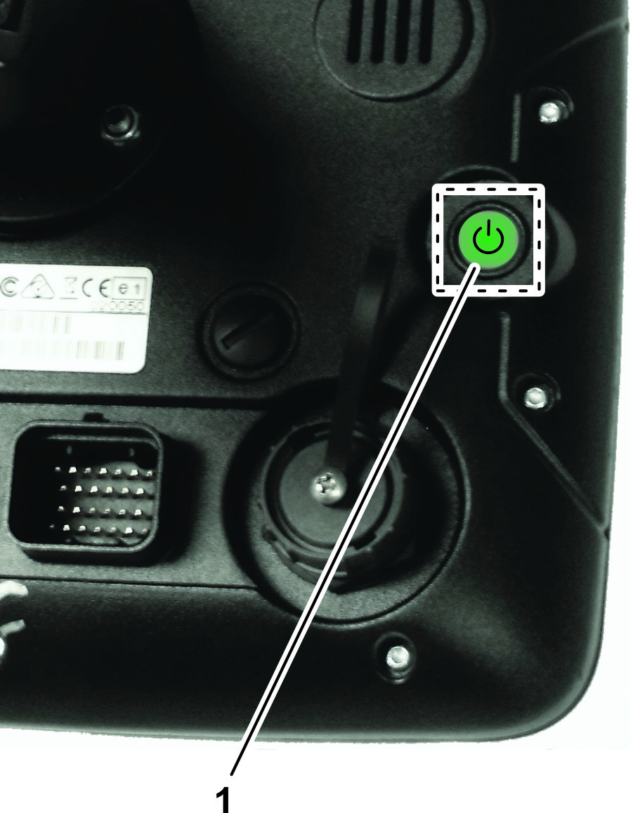
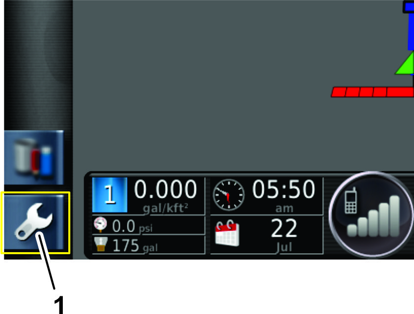
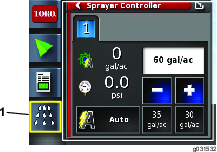
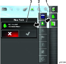
in the lower left of the home screen.
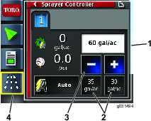
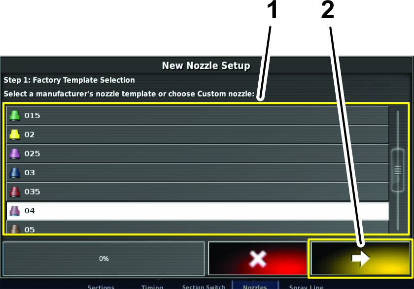
  3. Press the implement icon, boom icon, and nozzles icon (Figure 76).

    g204392
  4. On the nozzle setup screen, press the NEW NOZZLE... icon at the top of the screen (Figure 76).

  5. On step 1 of the new nozzle setup screen, press the icon for the new nozzle based on the flow rate or color listed in the factory template selection (Figure 77).

    Note: The following table shows the nozzles available from Toro. The settings are ISO standards.

    Note: The 015 nozzle (light green) is not the same as the 15 nozzle (dark green).The 03 nozzle (dark blue) is not the same as the 10 nozzle (light blue).

    g204393

    Nozzle Table

    NozzleNozzle ColorFlow Rate
    Graphic 04Red1.5 lpm (0.4 gpm)
    Graphic 05Brown1.9 lpm (0.5 gpm)
    Graphic 06Gray2.3 lpm (0.6 gpm)
    Graphic 08White3.0 lpm (0.8 gpm)
    Graphic 10Blue3.8 lpm (1.0 gpm)
    Graphic 15Green5.7 lpm (1.5 gpm)
  6. Press the NOZZLE NAME icon (Figure 78).

    g204394
  7. Enter the nozzle name with the display keyboard, and press the confirm icon (Figure 79).

    g204395
  8. In the new nozzle setup dialog box—step 2, press the confirm icon (Figure 79).

  9. In the new nozzle setup dialog box—step 3, press the confirm icon (Figure 79).

    g204396

Calibrating the Flow Meter

Customer provided equipment: A graduated catch container (a container with 0.01 ml (1/2 fl. oz) increments is preferred).

Preparing for the Calibration

  1. Ensure that the sprayer tank is clean.

  2. Fill the sprayer tank with at least 150 gallons of fresh water.

  3. Ensure that the nozzles that you intend to test are in the active spray (down) position.

  4. Engage the parking brake and start the engine.

    Note: Allow the engine and hydraulic system to warm for 10 minutes.

Performing the Pretest Priming

  1. Open the sprayer-controller icon and click on the icon in the upper right corner (Figure 81).

  2. Switch the sprayer to manual mode.

  3. Set all of the spray section switch(es) to the ON position.

  4. Set the throttle to the FAST position.

  5. Set the master section switch to the ON position.

    Note: The master section switch is located on the machine console.

  6. Turn on the sections using the master-section switch.

  7. Increase or decrease the pump speed to the desired spray pressure.

  8. Turn off the sections with the master section switch.

Running the Catch Test and Entering the Information

Note: 2 people are needed to perform the catch test in this procedure.

  1. Open the sprayer-controller icon and click on the expand icon in the upper right corner (Figure 81).

    g211485
  2. Set all of the spray section switch(es) to the ON position.

  3. Set the throttle to the FAST position.

  4. Set the master section switch to the ON position.

  5. Select the flow-meter icon (Figure 81).

    Important: Ensure the catch container is under the nozzle before turning on the sections.

  6. Place the catch container under the nozzle before turning on the sections (Figure 82).

    g193177
  7. Turn on the sections using the master-section switch.

  8. Perform the catch test for at least 15-seconds or more at 1 of the nozzles (Figure 82).

    Note: The length of the catch test depends on the size of the container, but more time is best.

  9. Shut off the master section switch, set the throttle to the slow position, and shut off the spray pump.

  10. Set the graduated container on a level surface and note the fluid volume (Figure 83).

    Important: When you are reading the graduated container, you must set the container on a level surface.

    Important: When you are reading the graduated container, read the fluid volume in the graduated container at the lowest point of the fluid-surface curve.

    Important: Small errors reading the fluid volume in the graduated container will significantly impact the accuracy of the sprayer calibration.

    g193829
  11. Using the fluid amount from the 1 nozzle, multiply that amount by the number of nozzles used to spray during the catch test. Then convert that amount into liters or gallons (128 fl oz equals 1 gallon).

    Example: 44 fl oz X 12 nozzles = 528 fl oz / 128 fl oz = 4.125 gallons

  12. Enter the fluid amount from the calculation with the key pad (Figure 84 and Figure 85).

    g211486
  13. Confirm the flow cal factor (Figure 85).

    g211487

Recording Job Details

The job menu selects or sets up specific job information associated with the chosen area. Use this menu to store information and record and report activity.

Recording Job Information

  1. Press the job icon (Figure 86).

    g203550
  2. Press the record-job information icon (Figure 86).

  3. Select the categories as needed and enter and confirm the information.

Recording Job Notes

Use the notes area to record any information for each job.

  1. Open the job-information icon (Figure 87).

    g203865
  2. Press the job-notes icon (Figure 87).

  3. Enter the information and press the confirm icon.

Exporting Job Information

Note: Ensure that a job is in session before exporting job information.

  1. Remove the cap for the USB port located below the power button (Figure 88).

    g212841
  2. Insert a USB storage device into the USB socket (Figure 88).

  3. Press the job-menu icon (Figure 89).

    g203551
  4. Press the data-exchange icon (Figure 89).

  5. Select the export Job Report to USB icon (Figure 89).

  6. Deselect the following in the job-report options menu:

    • Auto adjust ranges

    • Task data

  7. If required, select the create shape files option in the job-report options.

    Note: The shape file data is exported to D:/Client/Farm/Field/CoverageShapefiles and D:/Client/Farm/Field/BoundaryShapefiles.

    Note: This saves the job information to the USB storage drive.

    Note: Before removing the USB storage devise, always disconnect it electronically; refer to steps 8 through 10 that follow. If you do not do this, you may create a missing or corrupt report.

  8. Swipe the screen to access the floating-menu bar (Figure 90).

    g203571
  9. Press the eject USB icon (Figure 90).

  10. At the eject USB dialog box, press the confirm icon and remove the USB storage device from the monitor (Figure 90).

Setting up the System

Before operating the GeoLink spray system, perform the following procedures:

Note: The master section switch for the machine is at the following locations, refer to (Figure 91, Figure 92, or Figure 93).

g205126
g205127
g205125

Preparing the Machine

  1. Read through the following instructions before starting.

  2. Attach the supply hose to the anti-siphon tube and fill the tank half full of clean water.

    Important: Inspect and clean all system components before spraying, including the tank, strainer, pump, valves, and nozzles.

  3. Start the engine; refer to the Operator’s Manual for your machine.

  4. Move the throttle lever to the maximum setting.

  5. Set the console switches of the machine to the OFF position.

  6. Ensure that you have entered the proper calibration values.

Setting the Self-Test Feature

  1. Use the Test Speed feature as described in the Software Guide for the Multi-Pro 5800 Turf Sprayer for testing the spray system while the vehicle is not moving.

    Note: The self-test feature simulates speed so that you may test the system without moving. This feature clears itself when the speed sensor detects that the vehicle is in motion.

    To set the self-test feature, do the following:

    1. Open the ASC (Auto-section controller) icon (Figure 94).

      g203964
    2. Press the ASC icon to OFF (Figure 94).

    3. Press the sprayer-controller icon (Figure 95).

      g203966
    4. Press the switch window icon for the sprayer controller menu.

      The current home screen and the sprayer controller menu switches position.

    5. Press the configuration icon in the sprayer controller submenu to display to configuration menu (Figure 95).

      g203967
    6. Press the manual speed entry icon (Figure 97).

      g203965
    7. Use the key pad to enter the simulated speed and press the confirm icon (Figure 97).

  2. Press the switch window icon to return sprayer controller menu. (Figure 95).

  3. Enter the desired application rate by using the pre-sets, increase or decrease icons, or by selecting the current-target application rate icon (Figure 98).

    g204020

Initially Testing the System

Before operating the GeoLink spray system, perform this procedure.

Note: Use only water when performing this procedure.

  1. Drive the vehicle at the desired spraying speed with the sprayer booms off.

    The vehicle speed is displayed on the dashboard of the monitor.

  2. On the control console of the machine, press the master switch to the ON position.

  3. Ensure that the left, center, and right section switches are in the ON position.

  4. Set the master-section switch of the machine to the ON position.

    Note: Use the master-section switch to control all of the spray sections together.

  5. Set the rate control to AUTO.

    Note: Ensure that either the ASC is OFF or the boundary limit set to UNLIMITED.

  6. Select a target application rate.

  7. Increase or decrease the vehicle speed by 2 km/h (1 mph).

    The system should automatically correct the target application rate.

    Note: If the system does not correct the application rate, review Setting the Self-Test Feature.

  8. After spraying a swath, set the master-section switch to the OFF position.

    Note: This also shuts off the area calculations.

  9. Verify the area covered and the volume of material sprayed.

Restoring the X25 Software Configuration

Important: You must have Expert access level privileges to restore the software configuration. Please contact your authorized Toro distributor for assistance.

Alarm List

The table that follows lists the alarms and the alarm descriptions:

Alarm List

AlarmDescription
ASC 10 ECU firmware mismatchContact Toro NSN at 1-800-ASK-TORO or NSNTech@toro.com for customer service.
Exclusion map distanceThe exclusion map is to far from the current GPS position.
FallbackThe selected GPS correction source is not available and the system must use a less accurate correction source temporary.
Firmware version mismatch or out-of-dateContact Toro NSN at 1-800-ASK-TORO or NSNTech@toro.com for customer service.
Incorrect rateThe implement is in Auto mode and the target rate is not achieved.
Invalid or obsolete profile loadedAn old implement or vehicle profile is active on the system.
Low resourcesThe system resources (memory or space in the file system) are more that 90% full.
No CommsThe X25 control console is unable to communicate with the automatic section controller (ASC).
No GPSThe GPS signal is lost.
Parameter mismatchContact Toro NSN at 1-800-ASK-TORO or NSNTech@toro.com for customer service.
Pressure highThe pressure signal input has exceeded the alarm-point setting.
Receiver disconnectedThe GPS receiver is not responding.
Requested rate is zeroThe auto-rate control is enabled, the tank is On, the master switch is On, and the requested rate is zero.
Tank emptyThe calculated tank volume has reached zero.
Tank lowThe tank is running low (to the preset tank volume percent).

Operating Tips

Improving the RTK Reception

Reduce the machine speed when you are approaching an area with known RTK reception difficulty.

Using the Manual Control

To boost pressure for the hose reel and mixing chemicals, use the manual control to boost pressure.

Improving the Application Rate Response Time

Set the agitation PWM (preset agitation value) to approximately 69 kPa (10 psi) above the target-spraying pressure.

Maintaining Speed

Maintain a steady speed and direction in a straight line.

Creating a Backup File of Boundaries

Save a backup file of all field boundaries in an alternate location. Save the boundaries by installing a USB drive, selecting the inventory-manager icon, and selecting the options shown in Figure 99.

g208796

Maintenance

Recommended Maintenance Schedule(s)

Maintenance Service IntervalMaintenance Procedure
Every 200 hours
  • Clean the flowmeter (more often when using wettable powders).
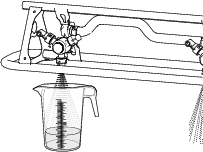
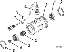
  • Cleaning the Flowmeter

    Maintenance Service IntervalMaintenance Procedure
    Every 200 hours
  • Clean the flowmeter (more often when using wettable powders).
    1. Thoroughly rinse and drain the entire spraying system.

    2. Remove the flowmeter from the sprayer and flush it with clean water.

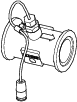
    3. Remove the retainer ring on the upstream side (Figure 100).

      g012934
    4. Clean the turbine and the turbine hub to remove metal filings and any wettable powders.

    5. Inspect the turbine blades for wear.

      Note: Hold the turbine in your hand and spin it. It should spin freely with very little drag. If it does not spin freely, replace it.

    6. Assemble the flowmeter.

    7. Install the sensor until it gently touches the bottom of the housing.

    8. Carefully tighten the sensor retaining nuts.

    9. Use a low pressure (50 kPa or 5 psi) air jet to ensure that the turbine spins freely. If it does not spin freely, loosen the hex stud on the bottom of the turbine hub by 1/16 of a turn until the turbine spins freely.

    Cleaning the Display Screen

    Clean the screen, when needed, with mild soap and water.

    Note: Avoid using window cleaners and any cleaners with solvents.

    Troubleshooting

    Note: If the computer in the X25 control console malfunctions or needs repair, you can control the sprayer system using the center-console controls of the machine.

    For many errors an error code, or trouble code, will display. It is also possible to view the errors on the screen. The errors listed below are common and are correctable. For other errors or if a problem persists, always record the error message to report to your distributor, including any code displayed.

    ProblemPossible CauseCorrective Action
    U1066
    1. The compass is not calibrated.
    1. Calibrate the compass.
    U1067
    1. A new vehicle has been detected.
    1. Calibrate the compass.
    U1082
    1. The compact flash file system has less than 1% space remaining.
    1. Confirm memory usage in the mini-view. It may be necessary to remove or transfer old files using the inventory manager.
    U3001
    1. The file transfer failed.
    1. Try exporting or importing the file from USB devise again.
    U5004
    1. The implement is not defined.
    1. Confirm the correct implement chosen.
    U6905
    1. An unknown machine type defined.
    1. Return to main setup menu, and revise vehicle setup.
    ProblemPossible CauseCorrective Action
    There is no power to the display.
    1. The harness connectors are not installed correctly.
    2. The in-line fuse (10 A) for the X25 control console is open (blown).
    3. The battery connections are loose.
    1. Ensure that the connectors are installed correctly at the back of the X25 control console.
    2. Replace the fuse.
    3. Secure the battery connections.
    The sprayer does not spray.
    1. The master-control switch for the machine is shut off.
    2. The section switch(es) on the console of the machine are off.
    3. No job and boundary is created.
    4. The incorrect nozzle is selected in sprayer-control setup menu.
    1. Ensure that the master-control switch for the machine is set to the On position.
    2. Ensure that the switches on the console are set to the On position.
    3. Create a job and boundary.
    4. Select the correct nozzle in sprayer-control setup menu that matches the nozzles being used.
    The No GPS alarm is on.
    1. The X25 control console is not connected to GPS receiver correctly.
    2. The machine is under trees or other obstructions.
    1. Ensure that the connections are installed correctly.
    2. Allow the machine to make connection after driving under obstructions.
    The sprayer sprays outside boundaries.
    1. The auto section control (ASC) is set to unlimited.
    1. Set the auto section control (ASC) to field boundary.
    You cannot create boundaries.
    1. The display is not in standard mode.
    2. There is no field created.
    1. Switch the user profile to standard mode.
    2. Create a field.
    The machine is not shown on the screen.
    1. The display screen has been moved.
    1. Select the center-map icon on the main screen.
    The lights are not blinking on the GPS receiver located on the ROPS.
    1. There is no power to the GPS receiver.
    1. Ensure that the connectors are installed correctly.
    The pressure is not high enough.
    1. The nozzle size used is incorrect.
    2. The nozzle size selected in the display does not match the nozzles on the boom sections.
    3. The agitation is set too low.
    1. Refer to the nozzle selection chart for the proper nozzle sizing.
    2. Ensure that the nozzle size selected in the X25 command console matches the installed boom-section nozzles.
    3. Adjust the agitation until the desired pressure is realized.
    The controller lights not on at the ASC 10 controller.
    1. There is no power to the ASC 10 controller.
    1. Ensure that the connectors are installed correctly.
    The speed is not displayed in the X25 control console when the machine is moving.
    1. The compass is not calibrated.
    2. The receiver lacks satellite reception.
    3. The vehicle ground speed is less than 0.16 km/h (0.1 mph).
    1. Calibrate the compass.
    2. Drive away from reception obstructions and allow time for the receiver to connect to the satellites.
    3. Increase the speed above 0.16 km/h (0.1 mph).
    There is condensation inside the display of the X25 control console.
    1. The display warms up too quickly in direct sunlight with the display set at 100 percent brightness.
    1. Change the screen brightness to 85 percent and allow the display to warm up.
    The X25 control console displays a crash report notification.
    1. Improperly powering down the console display.
    1. Clear the crash report from Inventory Manager. Always use the keys switch to shutoff the console display.