Contact Toro NSN at 1-844-GEOLINK (1-844-436-5465) or NSNTech@toro.com for customer service.
Note: When you turn on the machine with the display installed for the first time, the display is in standard mode. Ensure that the machine is stopped while changing the display console and configuration.
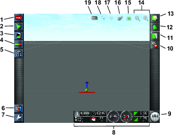
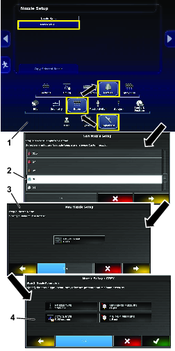
Using the Touch Screen
Sprayer information is added to the screen when you touch and enable the individual icons.
-
Select any icon on the screen to display what is shown on the screen.
-
Press on an icon to change it, and further options will display.
-
Select the options as required and confirm the new display (Figure 1).

Using the Standard Mode
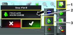
Creating a Field
Note: Create 1 field per course with all field boundaries for that course under that field.
-
Select the quick-start icon.
-
Select the field name, name the field, and confirm (Figure 3).
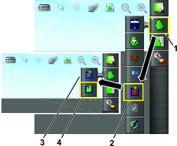
Creating a New Field Boundary
The boundary is created at the outside, center of the front, left tire.
-
Drive to the area.
-
Select the field-menu icon.
-
Select the record-field boundary icon.
-
Drive around the perimeter of the boundary.
-
When you are close to the beginning, select the complete boundary icon.
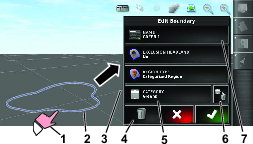
Naming and Categorizing a Field Boundary
Note: This is for RTK equiped machines only.
-
After creating a boundary, hold your finger on the boundary line.
-
When the boundary line is highlighted, remove your finger from the screen and the properties menu will open.
-
Select the different properties you want to change, input the information, and confirm.
Creating a Nozzle
-
Select the setup icon in the lower left of the main screen.
-
Select the implement icon, boom icon, and nozzles icon (Figure 6).
-
Select the new-nozzle icon at the top of the screen (Figure 6).
-
Select the nozzle based on size and color (Figure 6).
Note: The following table shows the nozzles available from Toro. The settings are ISO standards.
Note: The 015 nozzle (light green) is not the same as the 15 nozzle (dark green).The 03 nozzle (dark blue) is not the same as the 10 nozzle (light blue).
Nozzle Nozzle Color Flow Rate  04
04Red 1.5 L/min (0.4 gpm)  05
05Brown 1.9 L/min (0.5 gpm)  06
06Gray 2.3 L/min (0.6 gpm)  08
08White 3.0 L/min (0.8 gpm)  10
10Blue 3.8 L/min (1.0 gpm)  15
15Green 5.7 L/min (1.5 gpm) -
Press the NOZZLE NAME icon (Figure 6).
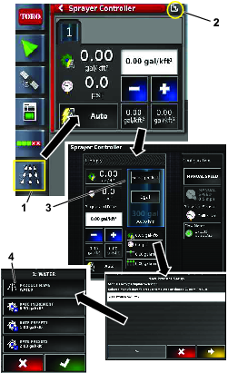
Using the Easy Mode
Creating a Product and Tank Volume
Note: Ensure the units are correct for your use. Refer to Selecting the Correct Units of Measure in the Operator’s Manual.
-
Fill the tank with water.
-
Select the sprayer-controller icon and expand the sprayer-controller panel.
-
Select the product title.
-
Select the custom product icon.
-
Name the product, select the rates, and select the rate increment (Figure 7).
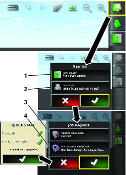
Creating a Job with the Quick-Start Icon
-
Select the quick-start icon in the upper right of the screen.
-
Enter a new name for the job (Figure 8).
Note: For the 1750 sprayers only, run the valve-balance wizard before selecting a nozzle.
-
Select the correct nozzle.
Note: Nozzles are created in the standard mode; refer to Creating a Nozzle.
-
Select the work region you are going to spray (i.e. fairways, greens, tees, etc.) (Figure 8).
-
Select the excluded regions that are not to be sprayed (bunkers, trees, hazards, etc.) (Figure 8).
Note: Refer to the standard mode videos for spraying a boundary inside another boundary.
-
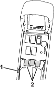
Turn the master switch to the ON position (Figure 9 or Figure 10).
-
Turn the section switches (located between the seats) to the ON position (Figure 9 or Figure 10).
-
To start spraying, turn on the master-switch icon (the master-switch turns green) and drive into the spray area (Figure 2).
Note: The machine starts spraying when the sprayer crosses into the correct spray area.
Note: The display shows areas to be sprayed with light gray and non-spray areas with a dark gray. If the display shows all light gray, you can spray every area.
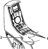
Note: The display, receiver, and section controller powers down when you turn the machine key to the OFF position. A power switch (green) for the display is located on the back, left side of the console.