Introduction

The vibratory plow is an attachment designed for use on the Toro Pro Sneak machine to pull flexible pipe and cable into and through soil. It is designed to be used by trained operators primarily for routing irrigation and utility lines underground without having to dig a trench for the entire length of the pipe or cable.

Read this information carefully to learn how to operate and maintain your product properly and to avoid injury and product damage. You are responsible for operating the product properly and safely.

You may contact Toro directly at www.Toro.com for product and accessory information, help finding a dealer, or to register your product.

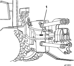
Whenever you need service, genuine Toro parts, or additional information, contact an Authorized Service Dealer or Toro Customer Service and have the model and serial numbers of your product ready. Figure 1 identifies the location of the model and serial numbers on the product. Write the numbers in the space provided.

g019062

This manual identifies potential hazards and has safety messages identified by the safety alert symbol (Figure 2), which signals a hazard that may cause serious injury or death if you do not follow the recommended precautions.

g000502

This manual uses 2 words to highlight information. Important calls attention to special mechanical information and Note emphasizes general information worthy of special attention.

Safety

Improper use or maintenance by the operator or owner can result in injury. To reduce the potential for injury, comply with these safety instructions and those in the machine Operator's Manual. Always pay attention to the safety alert symbol, which means Caution, Warning, or Danger—personal safety instruction. Failure to comply with the instruction may result in personal injury or death.

Danger

There may be buried power, gas, and/or telephone lines in the work area. If you dig into them, a shock or an explosion may occur.

Have the property or work area marked for buried lines and do not dig in marked areas. Contact your local marking service or utility company to have the property marked (in the United States, call 811 for the nationwide marking service).

Danger

Contact with the moving plow can cut or amputate hands, feet, or other body parts.

  • Keep your hands, feet, and any other part of your body or clothing away from moving parts.

  • Before adjusting, cleaning, repairing, and inspecting the plow, lower it to the ground, stop the engine, remove the key, and wait for all moving parts to stop.

Warning

When the engine is off, attachments in the raised position can gradually lower. Someone nearby may be pinned or injured by an attachment as it lowers.

Always lower the attachments whenever you shut off the machine.

Warning

The plow is very loud during operation; over time, your hearing may be impaired if unprotected.

Wear hearing protection during operation.

Warning

When the plow is out of the ground, bystanders could be injured by the swinging plow, and/or the machine could be overturned by the inertia of the swinging plow, crushing you or bystanders.

  • Keep the plow low at all times.

  • Use caution when turning, and do not turn quickly.

  • Keep all bystanders at least 2 meters (6 ft) away while operating.

Caution

Hydraulic couplers, hydraulic lines/valves, and hydraulic fluid may be hot and can burn you if you touch them.

  • Wear gloves when operating the hydraulic couplers.

  • Allow the machine to cool before touching hydraulic components.

  • Do not touch hydraulic fluid spills.

Warning

Hydraulic fluid escaping under pressure can penetrate skin and cause injury. Fluid accidentally injected into the skin must be surgically removed within a few hours by a doctor familiar with this form of injury or gangrene may result.

  • If equipped, make sure all hydraulic fluid hoses and lines are in good condition and all hydraulic connections and fittings are tight before applying pressure to hydraulic system.

  • Keep body and hands away from pinhole leaks or nozzles that eject high pressure hydraulic fluid.

  • Use cardboard or paper, not your hands, to find hydraulic leaks.

  • Safely relieve all pressure in the hydraulic system by placing the motion control levers in neutral and shutting off the engine before performing any work on the hydraulic system.

Safety and Instructional Decals

Graphic

Safety decals and instructions are easily visible to the operator and are located near any area of potential danger. Replace any decal that is damaged or lost.

decal125-6671
decal125-6684
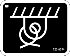
decal125-6694

Setup

Attaching the Plow

Parts needed for this procedure:

Locknuts4
Bolts4
Swing lock1
Washers10
Lynch pin2
Pivot pin2
Lift pin1
Snap ring4
Clevis pin1

Attaching the Plow Attachment Plate

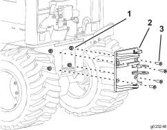
Secure the attachment plate to the machine using 4 bolts and 4 locknuts and torque to 321-392 N-m (237-289 ft-lb) (Figure 3).

g023248

Attaching the Plow Pivot Assembly

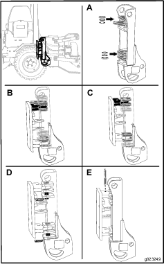
  1. Place 1 washer (1 inch) between the first and second plates and between the fourth and fifth plates on the plow assembly as shown in Figure 4; Box A.

    g023249
  2. Place additional washers below the first washer to shim the extra space allowing a gap from 0 to 1 washer clearance.

    Note: The number of flat washers will vary depending on the size of the tires installed.

  3. Place the pivot assembly onto the attachment plate as follows:

    • If the 23 inch tires are installed, place the pivot assembly onto the attachment plate so that the top ledge on the attachment plate is between the second and third plates on the plow assembly and the bottom ledge of the attachment plate is between the fifth and sixth plates on the plow assembly (Figure 4; Box B).

    • If the 26 inch tires are installed, place the pivot assembly onto the attachment plate so that the top ledge on the attachment plate is between the first and second plates on the plow assembly and the bottom ledge of the attachment plate is between the fourth and fifth plates on the plow assembly (Figure 4; Box C).

  4. Place the 2 plow pivot pins through the hole on the plates on the plow assembly, and secure them using the 2 lock pins (Figure 4; Box D).

  5. Place the swing lock pin through the hole on the attachment plate and the hole on the second plate of the plow assembly (Figure 4; Box E).

Attaching the Plow Assembly

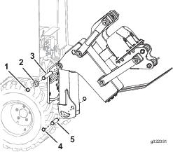
  1. Attach the plow assembly to the top of the pivot assembly, and secure them using the lift pin, 2 washers, and 2 snap rings (Figure 5).

    g022391
  2. Secure the bottom of the plow assembly to the pivot assembly using the clevis pin and 2 snap rings (Figure 5).

Routing the Hoses

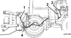
Connect the hose from port A to port A and repeat for port B to port B (Figure 6).

g022389

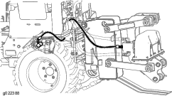
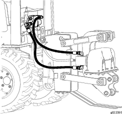
Connect the existing hoses as shown in Figure 7 and Figure 8.

g022388
g022390

Product Overview

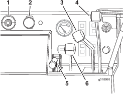
g018966

Throttle

Push the button at the center of the knob, and pull the knob to increase the engine speed (Figure 9).

Push the button at the center of the knob, and push the knob in to decrease engine speed.

Note: You can rotate the knob to make small adjustments to the engine speed. Rotate the knob counterclockwise to increase engine speed and clockwise to decrease engine speed.

PTO Switch

The PTO switch controls the vibratory plow.

Pull the switch to start the vibratory plow.

Push the switch to stop the vibratory plow.

Creep Control Lever

This lever controls the forward and reverse directions and the machine speed during operation. This lever has 5 positions: forward, reverse, neutral, right, and left. The machine will move in the direction that you move the lever. The farther you push or pull the lever, the faster the machine will move. The lever will lock in position when you release it.

Direction Control Lever

This lever controls the direction and speed of the machine.

This lever has 5 positions: forward, reverse, neutral, right, and left.

The machine will move in the direction that you move the lever. The farther you push or pull the lever, the faster the machine will move.

  • Move the lever to the neutral position to stop the machine.

  • From the neutral position, push the lever slightly for forward ground travel. Push the lever farther to increase the forward ground speed. Pull the lever slightly to decrease the forward ground speed.

  • From the neutral position, pull the lever slightly for reverse ground travel. Pull the lever farther to increase the reverse ground speed. Push the lever slightly to decrease the reverse ground speed.

  • While the machine is in motion push the lever slightly left or right to turn the machine.

Note: The directional control lever cannot be used to go forward or reverse when using the creep control lever.

Parking Brake Lever

To set the parking brake, pull the lever up and push it forward. To release the parking brake, pull the lever back and down.

Attachment Control Lever

The attachment control lever has 2 positions: raise and lower. Pull the lever to lower the attachment. Push the lever to raise the attachment.

Note: The specifications and design are subject to change without notice.

Width92 cm (36 inches) wheels mounted narrow117 cm (46 inches) wheels mounted wide
Length295 cm (116 inches)
Height211 cm (83 inches)
Weight1331 kg (2934 lb)

Operation

Refer to your machine Operator’s Manual for more information on installing and removing the attachments on your machine.

Important: Always use the machine to lift and move the attachment.

Plowing

  1. Start the engine.

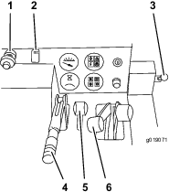
  2. When the engine is warm, pull the throttle out to full throttle (Figure 10).

    g019071
  3. If the machine is equipped with a trencher, move the attachment selector lever to the cable plow position (Figure 10).

  4. Use the attachment control lever to lower the plow to the ground.

    Note: The engine will turn off in 1 second if the operators seat is empty and the direction-control, trencher-digging-control, or creep-control levers are moved from the Neutral position.

  5. Release the parking brake.

    Note: Do not start the plow vibration until the blade tip has entered the ground.

  6. Pull the PTO switch to start the cable plow vibration.

  7. Slowly lower the plow blade into the ground as the machine moves forward.

  8. Use the creep control lever to control the direction and speed of the machine during plowing. The machine will move in the same direction that you move the lever.

    Note: The more you push the lever from the neutral position, the faster the machine will travel. The lever will stay in this position when you release the lever. Move the lever to the Neutral position to stop the machine travel.

  9. Use the direction or creep control levers to steer the machine to the left or right.

    Important: Do not reverse the machine with the plow blade in the ground.

    Important: Slowly lift the plow blade out of the ground as the machine moves forward.

    Note: Decrease the machine speed if the tires slip or the blade raises out of the ground during plow operation.

  10. Reduce the speed of the machine and press the PTO switch to stop the plow vibration before raising the blade out of the ground.

Changing the Plow Blade

The plow blades are heavy; use 2 people to complete this procedure.

  1. Park the machine on a level surface, lower any attachments, and stop the engine.

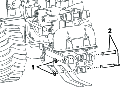
  2. Flip the 2 circular snap rings over and remove the snap-ring pin (Figure 11).

    g312471
  3. Pull the 2 pins out of the blade.

    Note: The plow blades are heavy. Make sure that 1 person is holding the blade while the other person is removing the pins.

  4. Place the new blade into the plow blade assembly and secure it with 2 pins and 2 snap-ring pins.

Removing and Installing the Skid Shoes

  1. Raise the plow about 91.4 cm (36 inches) off the ground.

  2. Stop the engine and remove the key.

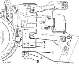
  3. Remove the 4 bolts, 4 nuts, and 8 washers from the skid shoes (Figure 12).

    g021986
  4. Install the new skid shoes and secure them with the previously removed hardware (Figure 12).

Maintenance

Recommended Maintenance Schedule(s)

Maintenance Service IntervalMaintenance Procedure
Before each use or daily
  • Grease the plow.
  • Before storage
  • Grease the plow.
  • Caution

    If you leave the key in the ignition switch, someone could start the engine. Accidental starting of the engine could seriously injure you or other bystanders.

    Remove the key from the ignition switch before you do any maintenance.

    Greasing the Plow

    Maintenance Service IntervalMaintenance Procedure
    Before each use or daily
  • Grease the plow.
  • Before storage
  • Grease the plow.
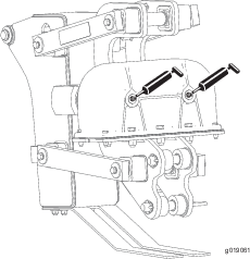
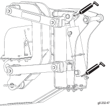
  • Grease the 4 fittings every 8 operating hours; refer to Figure 13 and Figure 14.

    Grease Type: General-purpose grease

    1. Stop the engine and remove the key.

    2. Clean the grease fittings with a rag.

    3. Connect a grease gun to each fitting.

    4. Pump grease into the fittings.

    5. Wipe up any excess grease.
    g019061
    g023247

    Storage

    1. Stop the engine and remove the key.

    2. Remove dirt and grime from the external parts of the attachment with a mild detergent and water.

      Important: Do not pressure wash the attachment. High-pressure washing can damage the electrical system and hydraulic valves or deplete grease.

    3. Grease the attachment; refer to Greasing the Plow.

    4. Check and tighten all bolts, nuts, and screws. Repair or replace any part that is damaged.

    5. Check the hydraulic hoses for leaks, loose fittings, kinked lines, loose mounting supports, wear, weather and chemical deterioration. Make necessary repairs.

      Warning

      Hydraulic fluid escaping under pressure can penetrate skin and cause injury.

      • If hydraulic fluid is injected into the skin it must be surgically removed within a few hours by a doctor familiar with this type of injury. Gangrene may result if this is not done.

      • Keep your body and hands away from pin hole leaks or nozzles that eject high-pressure hydraulic fluid.

      • Use cardboard or paper to find hydraulic leaks.

      • Safely relieve all pressure in the hydraulic system before performing any work on the hydraulic system.

      • Make sure that all of the hydraulic fluid hoses and lines are in good condition and all hydraulic connections and fittings are tight before applying pressure to hydraulic system.

    6. Paint all scratched or bare metal surfaces. Paint is available from your Authorized Service Dealer.

    7. Replace all worn or missing decals. Decals are available from your Authorized Service Dealer.

    8. Cover the attachment to protect it and keep it clean.

    Troubleshooting

    ProblemPossible CauseCorrective Action
    The plow does not operate.
    1. There is an obstruction in a hydraulic hose.
    2. A hydraulic hose is kinked.
    3. The auxiliary valve on the machine is not opening.
    1. Find and remove the obstruction.
    2. Replace the kinked hose
    3. Repair the valve.